COPYRIGHT PROTECTION OF PALETTE IMAGES BY A ROBUST LOSSLESS VISIBLE WATERMARKING TECHNIQUE
*Pei-Pei Chen (陳佩貝)1
and Wen-Hsiang Tsai (蔡文祥)
1,21
Dept. of Computer Science, National Chiao Tung University, Hsinchu, Taiwan
2
Dept. of Computer Sci. & Information Eng., Asia University, Taichung, Taiwan
ABSTRACT
A method for robust lossless visible watermarking of palette images for copyright protection against watermark removal attacks is proposed. A visible opaque watermark is embedded into a palette image according to a color mapping which is reversible.
The embedded watermark can be losslessly removed when the original image is needed. And the proposed method is made robust against watermark removal attacks by a scheme of a two-level color randomization in the watermark area using a user-specified key.
Experimental results show the effectiveness and robustness of the proposed method.
Keywords: palette image, opaque watermark, lossless visible watermark, robust, removal attack, copyright protection.
1. INTRODUCTION
In order to protect the copyright of images, digital watermarking techniques are proposed for embedding a pre-defined watermark into an image. There are two types of watermarking: invisible watermarking and visible watermarking. Traditional processes of invisible watermark and visible watermark embedding usually result in image distortions. Even though the distortions are tiny, in some applications like medical and military ones, such distortions are unacceptable due to the high precision requirements in these applications. This intensifies the demand for lossless watermarking techniques, which have the capability to recover original images from watermarked ones.
In addition to satisfying specific applications requirements, lossless watermarking techniques can save image owners a lot of storage space. The owner
*This work is supported partially by the NSC Project Advanced Technologies and Applications for Next Generation Information Networks (II) with Project No.
NSC93-2752-E-009-006-PAE and partially by the NSC National Digital Archives Program with Project No.
NSC93-2422-H-009-001.
can preserve only the stego-images instead of both the original images and their stego-versions, because by using lossless watermarking techniques they can obtain distortion-free original images from stego-images. Most of the lossless watermarking techniques focus on invisible watermarking [1]-[4], and few papers are found on lossy visible watermarking. A study is found in Hu et al. [5]. We are the first to study on lossless visible watermarking of palette images. To the best of our knowledge, there is no paper on lossless visible watermarking of palette images so far.
Typical visible watermarking techniques were proposed for reducing the distortions of stego-images, so semi-transparent watermarks are embedded traditionally. However, we choose to embed opaque watermarks into cover images in this study. Although an opaque watermark results in more visual distortion than a semi-transparent watermark, it has the advantages of better advertising effects and copyright declaration, and can be removed entirely by the proposed lossless watermarking technique when the image owner desires to get the original image.
In the remainder of this paper, we first describe the principle of the proposed method in Section 2. Then, we describe the watermark embedding technique in Section 3. Some experimental results are shown in Section 4, followed by conclusions in Section 5.
2. PRINCIPLE OF PROPOSED METHOD
Watermarks used in this study are assumed to be binary (black and white). The area in a cover image I where a watermark W is embedded is called the watermark area, denoted by IW, which is assumed to be at the upper left corner of I in this study. The group of the black pixels with values 1 in W will be denoted by Wb, and the remaining portion with values 0 denoted by Ww. The pixels in IW spatially corresponding to Wb in W will be called black watermark embedded pixels and the area of them will be denoted by IWb
, and the remaining pixels in IW will be called white watermark embedded pixels and the area of them denoted by IWw
. An illustration of the areas of IWb
and IWw
is shown in Figure 1.
The basic idea of the proposed method is to replace the colors of the pixels in IWb
with distinct colors in such a way that the replacement is revertible with a user-specified key. We try to find the most distinct colors among the palette colors for use in the color replacement. As a result, the embedded watermark looks opaque and visually very different from the adjacent pixels in the watermark area and can be removed losslessly with a right key. In addition, we apply a two-level key protection to ensure the embedded visible watermark remaining visible when an illegal user tries to remove it with a wrong key. More details will be described in the following section.
(a)
(b) (c) Figure 1 An illustration of pixels in a watermark. (a) A
binary watermark. (b) Area of black watermark embedded pixels (yellow pixels).
(c) Area of white watermark embedded pixels (yellow pixels).
3. LOSSLESS VISIBLE WATERMARK EMBEDDING
In Section 3.1, the visible watermark embedding process is introduced. And the process of lossless recovery of the original image is described in Section 3.2. A discussion on the robustness of the proposed recovery process against removal attacks is made in Section 3.3.
3.1. Watermark Embedding by A Neighborhood-Dependent Color Replacement Technique
Given a binary watermark W, we first divide the cover image I into a watermark area IW and a non- watermark area InW. We are only concerned about the area IWb
of black watermark embedded pixels in IW. The color of each pixel in IWb
will be replaced with another, and that of each pixel in the area IWw
of the white watermark embedded pixels will be kept unchanged.
Before the color replacement, we count the occurrences of the pixels’ colors in IWw
, and let the occurrence counts of the 256 colors C0 through C255 be denoted as O0 through O255, respectively. Then, we sort the color palette of I according to these counts in a descending order. We call the sorted result a sorted color palette Ps.
On the other hand, we propose the idea of adjusted Euclidean distance between colors which takes the concept of weighting into consideration, and call it weighted Euclidean distance. In more detail, the Euclidean distance between two colors C1 = (R1, G1, B1) and C2 = (R2, G2, B2) is defined as
µ(C1, C2) = [(R1 −R2)2 + (G1 − G2)2 + (B1 − B2)2]1/2. And the weighted Euclidean distance of color Ci in the color palette is defined as
255
0 255
0
( ( ) ( , ))
( )
( )
k i k
k i
k k
Occurrence C C C C
Occurrence C µ
µ =
=
×
=
∑
∑
.
where the function Occurrence(Ck) is the occurrence Ok
of color Ck counted only in the area IWw
of the white watermark embedded pixels in IW. The weighted Euclidean distance µ(Ci) of a color Ci may be figured out to be a measure of the distinctness of Ci with respect to the other colors in IWw; the larger the value µ(Ci) is, the more different the color Ci is.
Second, for each color Ci in the sorted color palette Ps, we compute its weighted Euclidean distance µ(Ci).
We then find accordingly the color with the largest weighted Euclidean distance and denote it by Cf. The color Cf is presumably the most different color from those in IWw
.
After finding Cf, we set up a table, with its entries beginning with the color in the palette Ps which is closest to Cf in the sense of Euclidean distance and ending with the color which is farthest to Cf. Obviously, the first entry of the table will the color Cf itself. The resulting table can be thought as a new color palette which has a different order from the original one Ps. And we call it a rearranged color palette Pr.
Having a sorted color palette Ps and a rearranged color palette Pr, we make a one-to-one mapping between the two palettes in such a way that if the original color C of a certain pixel ranks the ith in Ps, we map C to the color in the ith entry in Pr. Then we replace accordingly the colors of all the black watermark embedded pixels in IWb
with the corresponding colors in Pr by this mapping rule, thus obtaining a stego-image with a watermark appearing at the upper left corner of the image I. In the resulting stego-image, the pixels’ colors of IWb
can be seen to come from a group of colors, which look similar to one another but very different from the neighboring colors in IWw
.
Finally, in order to prevent illegal users from removing the embedded watermark easily, we apply a two-level key protection scheme when doing the above- mentioned color mapping. We add a random offset generated with a secret key to the original color order so that an illegal user cannot recover losslessly the original color easily. A noise-residual watermark will appear on the recovered image if a wrong key is used in the image recovery. In addition, we randomize the positions of the embedded watermark colors by the same key. The owner’s copyright of the image can thus be protected further. A detailed algorithm of the above-mentioned method is described in the following.
Algorithm 1: Lossless visible watermark embedding.
Input: A cover image I with a color palette P; a binary watermark W with size smaller than that of I;
and a user-specified key K.
Output: A watermarked image S.
Steps:
1. Divide the watermark area in I into an area IWb
of black watermark embedded pixels and an area IWw
of white ones.
2. Count the occurrences of the colors of the white watermark embedded pixels in IWw
. 3. Sort the colors in the color palette P of I
according to the occurrence counts obtained in the last step in a descending order to obtain a sorted color palette Ps.
4. Calculate the weighted Euclidean distance of every color in the color palette P, and choose the color Cf which has the largest weighted Euclidean distance.
5. Calculate the Euclidean distances between Cf
and each of the colors in the color palette P, and sort the colors according to the computed distances in an ascending order, resulting in a rearranged color palette Pr with the Cf being the first entry of Pr.
6. Embed each pixel t in the area Wb of the black watermark pixels of W into the original image I at the upper left corner in the following way.
6.1 Find the color Cm of the pixel t' in the original image I at the corresponding position of pixel t.
6.2 Find the rank n of color Cm in the sorted color palette Ps.
6.3 Add an offset generated randomly with the key K to the rank n to get a new rank n', and find the color Cm' of this new rank n' in Pr.
6.4 Replace the color of the pixel t' in the original image at the corresponding position of pixel t with the color Cm'.
7. Randomly pair the watermarked pixels together using the key K to form |Wb|/2 pairs of pixels, and then swap the colors of the two pixels in each pair.
3.2. Lossless Recovery of Original Images by Removal of Visible Watermarks
In this section, we describe how to recover the image losslessly and explain why we can achieve the goal.
In the watermark embedding process, we only replace the colors of the pixels in IWb
. Therefore, the colors of the pixels in IWw
are kept unchanged.
Moreover, the sorted color palette Ps and the rearranged color palette Pr were set up by taking into account only the colors of the pixels in IWw
. So in the recovery process, we can set up the two palettes which are respectively identical to the sorted and the rearranged color palettes Ps and Pr set up in the watermark embedding process. We let the corresponding area of IWb
in the input stego-image be denoted as SWb
and the corresponding area of IWw
in the stego-image as SWw
. Then we find the rank of each color C of SWb
in Pr, and replace it with the color of the same rank in Ps as the result of color recovery after using the secret key to get the right rank and the right position of color C. The details of the above-mentioned lossless recovery process of the original image colors are described as an algorithm as follows.
Algorithm 2: Lossless recovery of original image
.
Input: A watermarked image S; the original binary watermark image W; and the original user- specified key K.
Output: A recovered image R.
Steps:
1. Divide the watermark area in S into an area IWb
of black watermark embedded pixels and an area IWw
of white ones.
2. Count the occurrences of the colors of the white watermark embedded pixels in SWw
. 3. Sort the colors in the color palette P of S
according to the occurrence counts obtained in the last step in a descending order to obtain a sorted color palette Ps.
4. Calculate the weighted Euclidean distance of every color in the color palette P, and choose the color Cf which has the largest weighted Euclidean distance.
5. Calculate the Euclidean distances between Cf
and the other colors in the color palette P, and sort the colors according to the computed distances in an ascending order, resulting in a rearranged color palette Pr with the Cf being the first entry of Pr.
6. Pair the watermarked pixels together using the key K to arrive at the same |Wb|/2 pairs of pixels as done in watermark embedding, and then swap the colors of the two pixels in each pair.
7. Restore the color of each watermarked pixel t in SWb
to be its original color by the following way.
7.1 Find the color Ct of the pixel t.
7.2 Find the rank n of color Ct in Pr.
7.3 Subtract an offset generated by K from the rank n to get a new rank n', and find the color Cm with rank n' in Ps.
7.4 Replace the color Ct of the pixel t with the color Cm.
8. Take the final result of modified S as the desired recovered image R.
3.3. Noise-Residual Recovery against Removal Attacks
In order to provide protection of stego-images from illegal removal of the watermarks, we use a user- specified key in the above-described watermark embedding process by adding a random offset to the color rank found by the color mapping from the sorted color palette Ps to the rearranged color palette Pr in Step 5.3 of Algorithm 1. The range of the random rank offset is set to be between 0 and 20 in this study. After embedding the watermark with this way of protection, if an illegal user tries to remove the embedded watermark without a right key, a watermark-shaped noise region will survive in the recovered image. The larger the range of the offset is, the worse the quality of the embedded watermark will be, but the more obvious the noise region will appear in the recovered image.
Moreover, we randomize the positions of the embedded watermark colors by picking every two pixels of the embedded watermark and exchange each other’s color, as described in Step 7 of Algorithm 1. In this way, it is even more difficult for an illegal user to recover the original pixels’ colors in the watermark area.
Although this kind of randomization yields an opaque watermark which visually distorts the original image, it has the advantage of better advertising effects and copyright declaration.
4. EXPERIMENTAL RESULTS
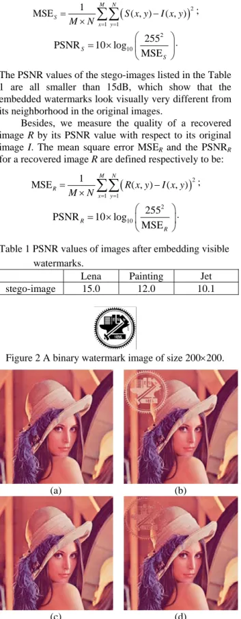
Some experimental results of applying the proposed method are shown in this section. A binary image of size 200×200 as shown in Figure 2 is used as the input watermark. The cover images are all with size 512×512 and the watermarks are positioned at the upper left corner of the cover images. Figure 3(a) is a color image of “Lena” and Figure 3(b) shows the resulting stego-image after embedding the watermark. Figure 3(c) shows the losslessly recovered image and Figure 3(d) shows the lossy recovered image with a wrong key.
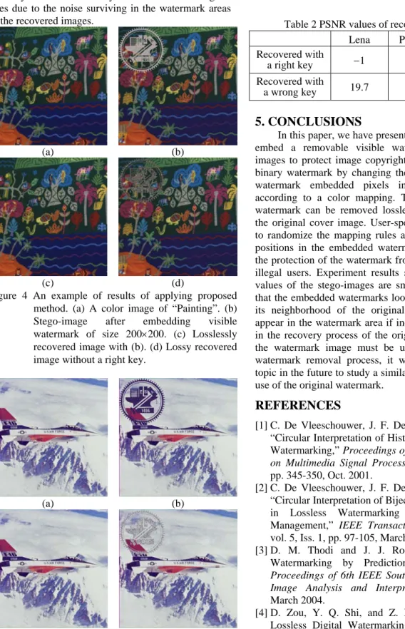
Figures 4 and 5 show two additional examples with the cover images of “Painting” and “Jet,” respectively. The corresponding peak-signal-to-noise-ratio (PSNR) values of (b) and (d) in these figures are shown in Table 1.
We measure the quality of a stego-image S by the PSNR value of the stego-image with respect to its cover image I. The mean square error MSES and the PSNRS
for a stego-image S after embedding a watermark W of size M×N are defined respectively to be:
( )
21 1
MSE 1 ( , ) ( , )
M N S
x y
S x y I x y M N = =
= −
×
∑∑
;2 10
PSNR 10 log 255
S MSE
S
⎛ ⎞
= × ⎜ ⎟
⎝ ⎠
.
The PSNR values of the stego-images listed in the Table 1 are all smaller than 15dB, which show that the embedded watermarks look visually very different from its neighborhood in the original images.
Besides, we measure the quality of a recovered image R by its PSNR value with respect to its original image I. The mean square error MSER and the PSNRR
for a recovered image R are defined respectively to be:
( )
21 1
MSE 1 ( , ) ( , )
M N
R
x y
R x y I x y M N = =
= −
×
∑∑
;2 10
PSNR 10 log 255
R MSE
R
⎛ ⎞
= × ⎜ ⎟
⎝ ⎠.
Table 1 PSNR values of images after embedding visible watermarks.
Lena Painting Jet
stego-image 15.0 12.0 10.1
Figure 2 A binary watermark image of size 200×200.
(a) (b)
(c) (d) Figure 3 An example of results of applying proposed
method. (a) A color image of “Lena”. (b) Stego-image after embedding visible watermark of size 200×200. (c) Losslessly recovered image with (b). (d) Lossy recovered image without a right key.
In Table 2, the PSNR values of the images recovered with right keys are all −1, which mean that the MSER values are all zero. That is, the recovered images and the original images are exactly the same.
And the PSNR values of the images recovered with wrong keys are smaller than 20dB, which show that the recovery results are still very different from the original ones due to the noise surviving in the watermark areas of the recovered images.
(a) (b)
(c) (d) Figure 4 An example of results of applying proposed
method. (a) A color image of “Painting”. (b) Stego-image after embedding visible watermark of size 200×200. (c) Losslessly recovered image with (b). (d) Lossy recovered image without a right key.
(a) (b)
(c) (d)
Figure 5 An example of results of applying proposed method. (a) A color image of “Jet”. (b) Stego- image after embedding visible watermark of size 200×200. (c) Losslessly recovered image with (b). (d) Lossy recovered image without a right key.
Table 2 PSNR values of recovered images.
Lena Painting Jet
Recovered with
a right key −1 −1 −1
Recovered with
a wrong key 19.7 17.0 16.0
5. CONCLUSIONS
In this paper, we have presented a novel method to embed a removable visible watermark into palette images to protect image copyright. We embed a given binary watermark by changing the colors of the black watermark embedded pixels in the cover image according to a color mapping. The resulting opaque watermark can be removed losslessly later to recover the original cover image. User-specified keys are used to randomize the mapping rules and the mapped color positions in the embedded watermark, thus increasing the protection of the watermark from being removed by illegal users. Experiment results show that the PSNR values of the stego-images are smaller than 15dB and that the embedded watermarks look very different from its neighborhood of the original images. Noise will appear in the watermark area if incorrect keys are used in the recovery process of the original image. Because the watermark image must be used in the proposed watermark removal process, it will be an interesting topic in the future to study a similar process without the use of the original watermark.
REFERENCES
[1] C. De Vleeschouwer, J. F. Delaigle, and B. Macq,
“Circular Interpretation of Histogram for Reversible Watermarking,” Proceedings of 4th IEEE Workshop on Multimedia Signal Processing, Cannes, France, pp. 345-350, Oct. 2001.
[2] C. De Vleeschouwer, J. F. Delaigle, and B. Macq,
“Circular Interpretation of Bijective Transformations in Lossless Watermarking for Media Asset Management,” IEEE Transactions on Multimedia, vol. 5, Iss. 1, pp. 97-105, March 2003.
[3] D. M. Thodi and J. J. Rodriquez, “Reversible Watermarking by Prediction-Error Expansion,”
Proceedings of 6th IEEE Southwest Symposium on Image Analysis and Interpretation, pp. 21-25, March 2004.
[4] D. Zou, Y. Q. Shi, and Z. Ni, “A Semi-Fragile Lossless Digital Watermarking Scheme Based on Integer Wavelet Transform,” Proceedings of 6th
IEEE Workshop on Multimedia Signal Processing, vol. 5, pp. 195-198, Sept.~Oct. 2004.
[5] Y. Hu, S. Kwong, and J. Huang, “An Algorithm for Removable Visible Watermarking,” IEEE Transactions On Circuits And Systems for Video Technology, Vol. 16, No. 1, January 2006.