Real-time Security Monitoring around a Video Surveillance Vehicle with a Pair of Two-camera
Omni-imaging Devices
Pei-Hsuan Yuan, Kuo-Feng Yang and Wen-Hsiang Tsai, Senior Member, IEEE
Abstract—A pair of two-camera omni-imaging devices is designed for use on the roof of a video surveillance vehicle and corresponding 3D vision-based techniques for real-time security surveillance around the vehicle are proposed, which may be used for monitoring passing-by persons around the vehicle. First, the design of the pair of two-camera omni-imaging devices, each device consisting of two omni-cameras with their optical axes vertically aligned, is described. Then, a new analytic technique for fast 3D space data acquisition based on a pano-mapping method for image-to-world space transformation and the rotational invariance property of the omni-image is proposed. Also proposed are techniques for constructing top-view and perspective-view images for convenient observation of the monitored environment.
Finally, 3D vision techniques for detecting automatically passing-by persons and computing their locations and body heights are proposed, followed by experimental results showing the precision and feasibility of the proposed techniques.
Index Terms—video surveillance, omni-camera, omni-image, 3D data acquisition, passing-by person detection, security monitoring, top-view image, perspective-view image.
I. INTRODUCTION
Video surveillance of environments has been studied intensively in recent years [1, 2]. In order to increase the mobility of the video surveillance system, vehicles are used as the carriers of such systems [3, 4, 5]. Applications of video surveillance vehicles include dynamic monitoring of outdoor events, detection of passing-by persons, assistance for safe driving, warning of dangerous activities, watching of environmental changes, etc. Various types of cameras were used to capture environment images. Gandhi and Trivedi [3]
made a good survey of vehicle surround capture techniques and proposed a novel omni-video based approach for synthesizing
dynamic panoramic surround maps using stereo and motion analysis of video images from a pair of omni-cameras on a vehicle. Micheloni, et al. [4] used an autonomous vehicle to monitor moving objects in indoor environments, Chen and Tsai [5] designed an autonomous vehicle to monitor planar objects on walls in buildings, and both works used projective cameras to capture environment images. Onoe et al. [6] and Mituyosi et al. [7] used omni-cameras for tracking human body features. A video surveillance system for localizing objects using multiple omni-cameras was proposed by Morita et al. [8]. Some related works using pairs of omni-cameras with hyperboloidal-shaped reflective mirrors can be found in [9, 10]. Specifically, Koyasu et al. [9] proposed an omni-directional stereo system consisting of two vertically aligned omni-cameras to detect and track obstacles. And Ukida et al. [10] used a similar system and a space encoding scheme to acquire 3D environment data for various applications. Furthermore, a method that reconstructs the 3D data of static nearby vehicles by a mobile robot using a stereo omni-camera (a two-mirror omni-imaging system) was proposed by Meguro et al. [11]. Many more related techniques can be found in [15-27], which will be reviewed after presenting the method proposed in this study.
Most of the above-mentioned works are about indoor visual surveillances and the speeds for computing the 3D data were generally slow. Some of the works used autonomous vehicles to carry the camera system. Very few studies about security monitoring were reported to use a video surveillance vehicle ⎯ a car equipped with a camera system on its roof. In this study, it is desired to design a video surveillance vehicle of this type equipped with an omni-imaging system for real-time wide-area monitoring applications, which has the following capabilities:
(1) constructing a top-view image of the video surveillance vehicle’s surrounding area for convenient observation of the environment security; (2) constructing a perspective-view image of any direction automatically or at any time instant specified by the user for real-time inspection; (3) detecting and displaying any suspicious passing-by person automatically; and (4) measuring the 3D features (location and height) of the passing-by person for security investigation purposes.
More specifically, for the specific purpose of security monitoring around a video surveillance vehicle, we design in this study an omni-imaging device which is composed of two
Manuscript received October 16, 2010. This work was supported by the NSC project No. 98-2221-E-009-116-MY3.
Pei-Hsuan Yuan was with the Institute of Multimedia Engineering, National Chiao Tung University, Hsinchu, Taiwan 300 and is now with Taiwan Semiconductor Manufacturing Company , Ltd., Hsinchu, Taiwan, 300 (e-mail:
Kuo-Feng Yang is with the Institute of Computer Science and Engineering, and Wen-Hsiang Tsai is with the Dept. of Computer Science, both at National Chiao Tung University, Hsinchu, Taiwan 300 (e-mails: castle7322.cs97g
@nctu.edu.tw, [email protected]).
catadioptric cameras with their optical axes vertically aligned, and affix a pair of such omni-imaging devices to the roof of a vehicle to acquire the environment data. One device is affixed to the right-front corner of the vehicle’s roof and the other to the left-rear corner (see Fig. 1(a)). A new method, which combines skillfully the uses of such a pair of omni-imaging devices, a so-called pano-mapping technique [12], as well as the rotational invariance property of the omni-image to compute the 3D data of real-world points, is then proposed. The computation is based on table lookup and analytic formulas and so can be carried out in real-time to construct both top- and perspective-view images for instantaneous observation of the vehicle’s surrounding environment. Also, a vision-based scheme using a vertical-line property in the omni-image for detecting passing-by persons, computing their locations and heights, and displaying such feature data both from the top and the perspective views for convenient inspection is proposed as well, which are not found in previous works. A detailed comparison of the proposed method with related existing methods will be given later.
In the remainder of this paper, the configuration of the proposed system, the design of the omni-camera system, and the proposed technique for computing 3D data are described in Section II. The proposed techniques for detection and monitoring of a passing-by person are described in Section III.
And the schemes proposed for generating top- and perspective-view images are described in Section IV, followed by some experimental results and a comparison of the proposed method with related methods in Section V. Finally, conclusions and descriptions of the contributions made in this study are given in Section VI.
(a) (b) Figure 1. Video surveillance vehicle and network used in this study. (a) Vehicle
with omni-cameras (circled in red). (b) Network connecting computers.
II. SYSTEM CONFIGURATION AND DESIGN OF PROPOSED
OMNI-IMAGING DEVICES
A. System Configuration
As illustrated in Fig. 1(b), the proposed system used in this study includes a video surveillance vehicle, a pair of two-camera omni-imaging devices CSA and CSB affixed on the vehicle’s roof, and two laptop computers COMA and COMB
inside the vehicle. Each two-camera omni-imaging device is controlled by a laptop computer, and a local network was designed to connect the two computers. Specifically, COMA is used to display the top-view image of the surrounding area of
the video surveillance vehicle, and COMB to display the perspective-view images of specified directions outside the surveillance vehicle. The system process is divided into two phases, the learning phase and the patrolling phase. In the former, the pano-mapping tables of the used omni-cameras are constructed in advance, and in the latter, the video surveillance vehicle is driven in the outdoor environment for real security monitoring applications.
B. Camera Design Principle
The structure of each catadioptric omni-camera with a reflective mirror of the hyperboloidal shape used in this study is illustrated in Fig. 2, where the world coordinate system (WCS) is specified by (X, Y, Z) with its origin Om located at the mirror base center which we assume to be coincident with one focal point of the hyperboloidal shape of the mirror. The shape of the mirror in the camera coordinate system (CCS), which is specified by (x, y, z) with its origin Oa located at the middle point between the point Om and the lens center of the projective camera, may be described [12] as
2 2
2 2
2 2 1,
s z
s x y
a −b = − = + (1)
where a and b are two parameters of the hyperboloidal shape.
The parameter d, as shown in Fig. 2(b), is the distance between the camera lens center and the mirror base center, whose value can be obtained by a simple formula d = 2c with c2 = a2 + b2. Also, the axis of the camera is aligned with that of the mirror, and the lens center is fixed at the other focal point of the mirror shape.
(a) (b) Figure 2. Omni-camera structure. (a) Omni-camera geometry. (b) Geometry
between hyperboloidal-shaped mirror and projective camera.
By the shape geometry of a hyperboloid described by (1), the value α specifying the elevation angle of a real-world point P shown in Fig. 2(a) can be computed [10] by:
2 2
2 2
( )sin 2
tan ( ) cos
b c bc
b c
+ −
= −
α β
β (2)
where the angle β as shown in Fig. 2(a) can be computed as:
β = π /2 − θ (3)
with
θ = tan−1(r/2c) (4)
where r is the distance of P to Om on the XY plane and equals the radius of the circular mirror base when α = 0. In Fig. 2(b), by the principle of similar triangles, we have
w
d f
r =S (5)
Computer A
Cross-over cable
Camera system B Video surveillance vehicle
Computer B Camera system A
where f is the focal length of the projective camera and Sw is the width of the square CMOS sensor in the camera.
The goal of omni-camera design in this study is to construct a mirror of the hyperboloidal shape and determine the distance from the camera to the mirror under the constraint that f, Sw, and r are of given values which fits the structure of the vehicle roof.
The projective camera we use has f = 6 mm and Sw = 2.4 mm, and to affix the cameras to a steel rod on the vehicle roof, we chose the mirror to have a base with an appropriate radius r of 4 cm. So, according to (5) and the previously-mentioned fact that d = 2c, we can derive d and c respectively to be d = 10 cm and c
= 5 cm. Also, according to (3) and (4) and with α assumed to be zero, the values of the angles θ and β can be computed to be θ = 21.8o and β = 68.2o. Finally, using β and c, we may reduce (2) to be an equation with only one variable b of the following form
(b2 + 25)×0.9285 − 10×b = 0
which may then be solved to get b = 3.39 cm. And by c2 = 52 = a2 + b2, a can be solved to be 3.68 cm. Thus, all of the desired parameters of the hyperboloidal-shaped mirror are obtained: a
= 3.68, b = 3.39, c = 5, d = 10, all in the unit of cm.
C. 3D Data Acquisition
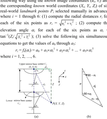
Each omni-imaging device used in this study consists of two omni-cameras designed in the way described above. The two cameras, one called the upper and the other the lower, are tied together, with their mirrors both facing down and their axes vertically aligned. An alternative illustration of the upper omni-camera configuration is shown in Fig. 3, where the image coordinate system (ICS) is specified by (u, v) with the image center as its origin, and a pixel p with image coordinates (u, v) corresponds to a real-world point P with coordinates (X, Y, Z).
Figure 3. Configuration of an upper omni-camera with a mirror.
In this study, a new technique is proposed to compute the 3D data, (X, Y, Z), of each real-world point P in the WCS by the use of the two elevation angles α1 and α2 of P with respect to the mirror bases of the two omni-cameras in an omni-imaging device, as illustrated in Fig. 4, where the values of α1 and α2
may be obtained by using a pano-mapping method proposed by Jeng and Tsai [12].
More specifically, as shown in Figs. 3 and 4(a), each image pixel p is the projection of a real-world point P whose light ray goes onto the mirror of the omni-camera and is then reflected onto the camera imaging plane, resulting in an azimuth angle θ (shown in Fig. 3) and an elevation angle α (shown in Fig. 4(a)
as α1 or α2). By the pano-mapping method proposed in [12], given the image coordinates (u, v) of an image pixel p corresponding to a real-world point P, the elevation angle α and the azimuth angle θ of P can be obtained by table lookup using a pano-mapping table. An example of the pano-mapping table is shown in Table 1. Also, according to the mirror surface geometry which we assume as usual to be radially symmetric, a relationship, called the radial stretching function and denoted as fs, between the elevation angle α and the radial distance r of p in the image plane with respect to the image center is established to be:
r = fs(α) = a0 + a1×α1 + a2×α2 + … + a5×α5
where the coefficients a0 through a5 are computed in the following way using the known image coordinates (ui, vi) and the corresponding known world coordinates (Xi, Yi, Zi) of six real-world landmark points Pi selected manually in advance, where i = 1 through 6: (1) compute the radial distances ri for each of the six points as ri = ui2+vi2 ; (2) compute the elevation angle αi for each of the six points as αi = tan−1(Zi/ Xi2+Yi2 ); (3) solve the following six simultaneous equations to get the values of a0 through a5:
ri = fs(αi) = a0 + a1×αi1 + a2×αi2 + ... + a5×αi5 where i = 1, 2, …, 6.
(a) (b) Figure 4. Computing 3D data. (a) Ray tracing of a real-world point P in an
imaging device. (b) Blue triangle in (a) shown in detail.
Table 1. An example of pano-mapping table of size M×N [12].
θ1 θ2 θ3 θ4 … θM
α1 (u11, v11) (u21, v21) (u31, v31) (u41, v41) … (uM1, vM1) α2 (u12, v12) (u22, v22) (u32, v32) (u42, v42) … (uM2, vM2) α3 (u13, v13) (u23, v23) (u33, v33) (u43, v43) … (uM3, vM3) α4 (u14, v14) (u24, v24) (u34, v34) (u44, v44) … (uM4, vM4)
... … … …
αN (u1N, v1N) (u2N, v2N) (u3N, v3N) (u4N, v4N) … (uMN, vMN)
With a0 through a5 derived, a pano-mapping table like that of Table 1 is then constructed in the following way: for each real-world point Pij with azimuth-elevation angle pair (θi, αj), compute the coordinates (uij, vij) of the corresponding image pixel pij as
uij = rj×cosθi; vij = rj×sinθi
where rj = fs(αj) = a0 + a1×αj1 + a2αj2 + … + a5×αj5. After the table is constructed, when an image pixel p with coordinates (u, v) in a given omni-image is given and checked by table lookup
to be located in entry Eij with coordinates (uij, vij) in Table 1, the azimuth-elevation angle pair of the corresponding real-world point P can be obtained to be (θi. αj). Note that this azimuth-elevation angle pair only says that P is located on a light ray R with the azimuth direction θi and the elevation angle αj; it does not specify the 3D position of P sufficiently ⎯ any real-world point on light ray R will appear identically to be the pixel p in the image with the same coordinates (uij, vij). Also note that the pano-mapping table involves no camera parameter and is invariant in nature with respective to the camera position (i.e., it is not changed when the camera is moved around).
Back to the discussion about computing the 3D coordinates for a real-world point P in the WCS. Since two omni-cameras are used in each imaging device, after the two image pixels p1
and p2 corresponding to real-world point P are identified in the two omni-images taken by the two cameras, two elevation angles α1 and α2 as shown in Fig. 4(a) can be obtained by the above table lookup process using the image coordinates (u1, v1) and (u2, v2) of p1 and p2, respectively. With the upper mirror base center being located at the WCS origin with world coordinates (0, 0, 0), the goal of 3D data computation now can be achieved by using α1 and α2 to compute the world coordinates (X, Y, Z) of P. For this, as shown in Fig. 4(b), by the law of sines in trigonometry, we have:
2 1
sin(90 ) sin( )
dP = e
+α α α− 2 (7)
where dP is the distance between P and the base center of the upper mirror C1, and e is the disparity between the two cameras in the omni-imaging device, which is measured manually in advance. Eq. (7) may be reduced to get dP as:
1 1 2
1
cos tan tan
P
d e
α α α
= ×
− . (8)
And so the horizontal distance dw and the vertical distance Z of P as shown in Fig. 4(a) may be computed respectively to be:
w 1
1 2
cos tan tan
d dP α e ;
α α
= =
−
1 1
sin tan
P
Z d e
1 2
tan tan α α
α α
= = ×
− . (9)
Furthermore, according to Fig. 3, the azimuth angle θ in the figure can be described in terms of the pixel coordinates (u, v) as follows:
2 2 2 2
u
u +v u +v
sinθ= v ; cosθ= (10)
from which the value of θ in the ICS can be computed.
Now, according to the characteristic that the axes of the cameras are aligned with the axis of the mirror, the rotational invariance property of the omni-camera says that the azimuth angle of point P in the WCS and the azimuth angle of the corresponding pixel p in the ICS are identical [12]. Denoting both of the angles by θ, we can compute the values of X and Y in the WCS as:
w
1 2
cos ;
tan tan
X d θ e cosθ
α α
= × =
−
× (11)
w
1 2
sin sin
tan tan
Y d θ e θ
α α
= × = ×
− . (12)
In summary, given a pair of matching image points corresponding to a real-world point P, we can compute the azimuth θ of P by Eqs. (10), and obtain also a pair of elevation angles α1 and α2 of P by pano-mapping table lookup. Then, the world coordinates (X, Y, Z) describing the unique 3D position of P can be computed by Eqs. (9), (11), and (12) analytically.
III. AUTOMATIC DETECTION OF PASSING-BY PERSONS
A. Detection of Moving Objects in Omni-images
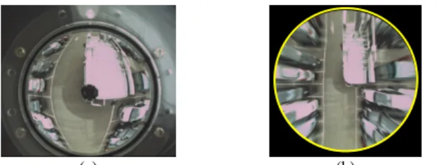
Before extracting moving objects around a surveillance vehicle, background images without objects are captured in advance in the learning phase with the vehicle in a static state, or, whenever necessary, in the patrolling phase with the vehicle also in a static state. An example is shown in Fig. 5. Then, foreground images possibly with objects are taken in real-time in the patrolling phase. Both background and foreground images are color ones, which are transformed into grayscale ones at the beginning of the object detection process. By subtracting the background image from the foreground one, a difference image is obtained. Because there usually exist noise pixels in the difference image, such as those caused by light variations, the difference image is thresholded next into a binary one to eliminate such noise pixels using the moment-preserving thresholding technique proposed by Tsai [13]. After these steps, we can obtain a bi-level image Ibl with detected moving objects all labeled as black pixels. An example of the result is shown in Fig. 6.
(a) (b) Figure 5. Background images taken by a two-camera imaging device. (a)
Background taken by upper camera. (b) Background taken by lower camera.
(a) (b)
(c) (d) Figure 6. Passing-by person detection. (a) Background image. (b) Foreground
image. (c) Difference image obtained by subtracting (b) from (a) (d) Binary image obtained by bi-level thresholding.
B. Detection of a Passing-by Person’s Head
As illustrated in Fig. 7, the proposed technique to detect a passing-by person’s head is based on a vertical-line property of the omni-image: each line L, which is parallel to the Z-axis in the WCS and so vertical to the ground, is projected onto the image as a line IL going through the image center. This means that if a passing-by person stands on the ground, the midline IL
of the person’s silhouette will go through the image center Oc, as illustrated in Fig. 8(a). So, we may find the top of each passing-by person’s head by the following steps: (1) transform the rectangular image coordinates (u, v) of the bi-level difference image Ibl into polar ones (θ, r) where θ is the azimuth angle and r the radial distance; (2) scan each radial line inward from the image boundary to the image center based on the use of (θ, r); (3) find each sufficiently-long line segment in Ibl and group neighboring segments so found into a set Ls; (4) find the farthest line-segment end point in Ls with respect to the image center as the passing-by person’s head location. If non-human objects will appear possibly in the omni-image, Step (3) should be refined using features like the width of the set Ls (equal to the number of line segments in Ls which means the width of the person) to differentiate and exclude them. The result of applying this process to Fig. 6 is shown in Fig. 8(b). Another result of detecting two persons is shown in Figs. 8(c) and 8(d).
Figure 7. A vertical-line property of omni-camera: projection of a vertical line
in real world will result in a line in omni-image going through the image center.
(a) (b)
(c) (d) Figure 8. Passing-by person’s head detection (a) Middle line of a person going
through image center. (b) Result of one-person detection of Fig. 6(d) (head marked in red). (c) and (d) Result of two-person detection (feet and heads marked in red and green).
C. Computation of Passing-by Person’s Location and Height With the passing-by person’s head location detected in the
upper and lower images taken by an omni-imaging device, the formulas derived in Section II.C may be used to compute the location (X, Y) of the person and his/her body height h.
Specifically, the coordinates (X, Y) are just those described by Eqs. (11) and (12). And as can be figured out easily from Figs.
4 and 7, the person’s body height h may be computed as:
h = dh − Z (13)
where dh is the height of the upper camera with respect to the ground and Z is as that computed by Eq. (9) because P is the passing-by person’s head point (shown as the red point in Fig.
8(b)). Note that the origin of the WCS is located at the mirror base center of the upper omni-camera. Also, by a back projection of the person’s feet location at (X, Y, dh) in the WCS into the omni-image, the person’s feet can be marked for easier observation (e.g., see the color points in Fig. 8(c)).
Detection of passing-by persons and computation of their location and height features as described previously is based on the technique of background subtraction, which, though requiring background image updating whenever necessary, still has many applications with a video surveillance vehicle as the working platform, like car driver identification, alert-region protection, car stealing prevention, passing-by person counting, violent attack warming, etc.
IV. GENERATION OF TOP- AND PERSPECTIVE-VIEW IMAGES
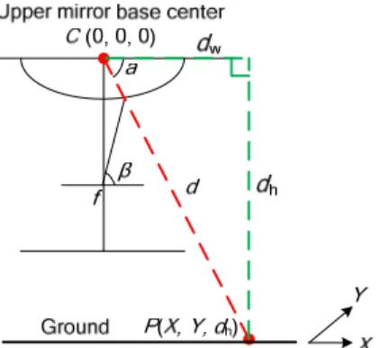
A. Construction of Top-view Images Using Upper Cameras Because the field of view (FOV) of the upper camera in an imaging device is wider than the lower one, we use the upper camera to construct a top-view image of the video surveillance vehicle’s surrounding area. The height dh of the camera affixed on the vehicle’s roof is known in advance by manual measurement. Also, for simplicity it is assumed that all pixels around the vehicle in the image are projections of real-world points on the ground, as illustrated in Fig. 9.
Figure 9. Ray tracing of a real-world point P on ground onto the mirror.
We adopt a backward-mapping scheme based on the use of the pano-mapping table to compute the desired top-view image.
First, according to Fig. 9 we may compute the horizontal distance, dw, between a ground point P and the mirror base center C in terms of the coordinates (X, Y, dh) of P in the WCS as follows:
2 2
dw= X +Y . (14)
Accordingly, the azimuth angle θ of P can be derived as:
cos ; sin .
u r v r
θ = cos−1(X/dw) = sin−1(Y/dw). (15) On the other hand, because dw = dh×cotα where dh is the height of the upper camera’s mirror base, we can compute the elevation angle α of P by:
α = tan−1(dh/dw). (16) Furthermore, using the radial stretching function r = fs(α) mentioned previously, the radial distance r corresponding to α can be derived. Accordingly, by the rotational-invariance property of omni-imaging, the coordinates (u, v) of the image pixel p corresponding to P can be obtained from (15) as:
θ θ
= =
feasible to superimpose a real surveillance vehicle shape Srv on
ch pi
(17) As a result, a complete top-view image can be computed. A top-view image of a parking area so computed with the surveillance vehicle in the middle is shown in Fig. 10. Note that all the cars appearing in the figure are distorted, and this phenomenon comes from their violation of the assumption that the processed points are projections of real-world points on the ground, as mentioned previously. However, the result is still good for visual inspection of the vehicle’s surround.
(a) (b) Figure 10. An omni-image and its corresponding top-view images. (a)
Omni-image. (b) Top-view image obtained from backward mapping.
B. Merging of two top-view images into a single one
By the way describe above, we can construct two top-view images It1 and It2 using the omni-images taken from the two upper cameras, like those shown in Figs. 11(a) and 11(b). It is assumed that the relative position of the two upper cameras on the vehicle roof are measured manually in advance and described by a pair of offsets (CW, CL) with CW and CL being the horizontal and vertical distances between the two imaging devices, respectively. It is desired to merge the two top-view images It1 and It2 into a single one, denoted as Iint, to get a wider FOV of the vehicle’s surround. To do this, we divide first the FOV covered by the desired top-view image Iint into two parts:
one from the upper half of It1, and the other from the lower half of It2. All the pixels in the latter part then are shifted for the offset (CW, CL) before being merged into the former. An example of a top-view image so obtained is shown in Fig. 11(c).
To obtain a better-looking top-view image, an elliptical shape is used further as a viewing window, and all the pixels outside the window are discarded, yielding an elliptical-shaped image. For Fig. 11(c), the result of this process is shown in Fig. 11(d).
C. Superimposition of Surveillance Vehicle Shape on Top-view Image
Because the imaging devices are affixed on the vehicle’s roof, the vehicle shape in the top-view images always appears at fixed locations in the taken omni-images. Therefore, it is
the elliptical-shaped top-view image like that in Fig. 11(d) as the central landmark of the image, making observation of the vehicle’s position in the surround more convenient. For this, the following steps are conducted: (1) trace and segment out manually the real top-view shapes S1 and S2 of the surveillance vehicle in the two top-view images It1o and It2o, respectively in the learning phase; (2) superimpose S1 and S2 respectively on It1
and It2 acquired in each patrolling phase to segment out by image matching, and mark in yellow the surveillance vehicle’s shape area A in It1 and It2 before they are merged into one, resulting in a figure like that shown in Fig. 12(a); (3) apply a texture synthesis scheme to fill ground texture into the marked surveillance vehicle shape area A; and (4) superimpose a pre-segmented real top-view vehicle shape Srv like that shown in Fig. 12(b) on the resulting image of the last step, yielding a better-looking output image like that shown in Fig. 12(c). Note that Srv is obtained in the learning phase by manual segmentation from a top-view image like that of Fig. 11(a).
Step (3) above is carried out by the following way: for ea xel pc in the surveillance vehicle shape A, find the pixel pn
which is outside A and closest to pc, and use the color of pn to fill up pc. Also, the relations of pixels in A with those outside A are kept in a table for use in the later top-view image generation process to improve the top-view image display speed.
(a) (b)
(c) (d) Figur uction. (a) Right-front top-view im (b)
Figur posing real surveillance v top-view
D. Generation of Perspective-view Images
The construction of a perspective-view image IP from an
e 11. Top-view image constr age.
Left-rear top-view image. (c) Integrated top-view image (red dots: centers of original images). (d) Top-view image viewed in an elliptical shape.
(a) (b e 12. Superim
) (c) ehicle shape onto
image. (a) Top-view image with vehicle shape marked in yellow. (b) Pre-segmentd real shape of video surveillance vehicle. (c) Result of ground texture filling and superimposition of real surveillance vehicle shape.
no-mapping table [1
distance D to the mirror base center O an
dth W of Ip as shown in Fig.
cosines to satisfy the eq
(a) (b
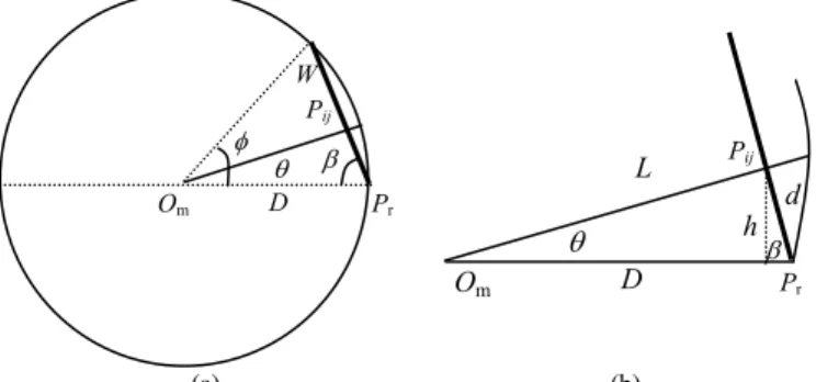
Figure 13. Illustration of top view of a g age.
L between point P and the mirror base center O as shown in Fig.
13
omni-image Io is based on the use of the pa
2]. The major steps include: (1) map each pixel p in the desired perspective-image IP at coordinates (k, l) to a pair of elevation and azimuth angles (α, θ) in the pano-mapping table according to the geometry of the desired perspective transformation; (2) find the image coordinates (u, v) in the table entry corresponding to (α, θ); and (3) assign the color channel values of pixel p in IP to be those of the pixel at coordinates (u, v) in Io. The detail of mapping (k, l) to (α, θ) in Step (1) is described as follows.
Assume that the perspective-view image Ip we want to
generate from Io is at a m
d has Mp×Np pixels. Also assume that Ip is the image of a planar rectangular region AP with size W×H and is perpendicular to the floor in the real-world space, as illustrated from the top view by Fig. 13.
(a) Computing the azimuth angle θ ⎯ The angle φ spanned by the wi 13(a) may be derived by the law of
uality W2 = D2 + D2 − 2×D×D×cosφ so that φ may be computed as φ = cos−1[1 − W2/(2D2)]. Also, the angle β in the figure is just β = (π − φ)/2. Next, let Pij denote the intersection point of the light ray RP projected onto the image pixel p and the planar region AP mentioned previously. Then, we may compute the distance d between point Pij and the border point Pr shown in Fig. 13(b) by linear proportionality to be d = k×W/MP
because AP has a width of W, Ip has a width of Mp pixels, and pixel p has the coordinate k in the horizontal direction.
) enerated perspective-view im
Furthermore, by the law of cosines again the distance
ij m
(b) satisfies the equality L2 = D2 + d2 − 2×d×D×cosβ. Also, the distance h from point Pij to the line segment OmPr may be computed as h = d×sinβ.Finally, the azimuth angle θ of point Pij with respect to OmPr satisfies sinθ = h/L which, by the equalities derived above, leads to the following desired value:
θ = sin−1(h/L) = sin [1 2 2 sin ].
2 cos
d
D d d D
− ×
+ − × × ×
β
β (18)
(b) Co ation angle ⎯
An illustration of the involved imaging configuration for lateral view is shown in Fi
p
This completes the deriv pair (θ, α) conducted in
Figure 14. Lateral configuration for generating a perspective-view image.
Mouse Clicks or Panel Touch
to e perspective-view image co
hich shows a pe
Similarly, we define anot valu mouse click locat t
mputing the elev
computing the elevation angle α from a
g. 14. The height of region AP is H and image Ip is divided into Np intervals in the vertical direction. And so, by linear
proportionality again, the height of Pij may be computed to be Hp = (l×H)/Np where l is the coordinate of pixel p in the vertical direction. Finally, by trigonometry, the desired elevation angle α may be derived to be:
α = tan−1(H /L). (19)
ations of the azimuth-elevation angle Step (1) mentioned above. Note that in these derivations, the start direction (specified by the line segment OmPr) of the angle φ spanned by the width W of Ip, as shown in Fig. 14, coincides with the horizontal direction 0o, resulting in the azimuth angle θ. Of course, perspective-view images for other azimuth angles may also be generated. A convenient scheme to do this is described next.
E. Generation of Perspective-view Images Specified with In this study, a technique is proposed to enable a user change the view direction of th
nveniently by mouse clicking, or equivalently, by panel touching). Fig. 15(a) shows a perspective-view image generated from the omni-image shown in Fig. 15(b). According to the previous derivations and an observation of the images in the figure, we can see that there exists a relation between the mouse motion direction and the viewing direction of the generated perspective-view image. Specifically, the horizontal motion of a mouse specified by its horizontal location Mx may be used to define the azimuth angle θ of the space point Pc
corresponding to the image center pc; and similarly the vertical motion of the mouse specified by its vertical location My may be used to define the elevation angle α of Pc.
Accordingly, as an interaction with the proposed system via mouse clicking on the computer screen w
rspective-view image like that of Fig. 15(a), we define in this study an angle value θmouse according to the mouse click location in the horizontal direction so that θmouse becomes larger and larger as the mouse moves from right to left in the image of Fig. 15(a); and then modify the equation for computing the azimuth angle, namely, Eq. (18), derived previously to be:
θ = sin−1(h/L) + θmouse. (20)
α
her angle e mouse according to the ion in he vertical direction such that αmouse Om
Pij
β Pr
D θ h
(d L
αe
Om
N D
H
αs
α
Hp perspective- view image Ip
l Pij
Np
Pr
φ β
Om D
W θ
Pij
two variables θmouse an
(a) (b)
increases gradually as the mouse moves from top to bottom in Fig. 15(a); and then modify Eq. (19) to be:
α = tan−1(Hp/L) + αmouse. (21)
The user interface becomes friendlier after adding the d αmouse, and a user of the surveillance vehicle can now choose any view direction conveniently by mouse clicking (or panel touching) to observe the corresponding perspective-view image of a scene of his/her interest. Two more experimental results of perspective-view images generated in this way are shown in Figs. 15(c) and 15(d).
(c) (d) Figure 15. Corresponding omni-image and perspective-view image.
perspective-view image. (b) Omni-image part (enclosed roughly by e ed triangle) from whi ) was generated. (c) and (d) Two o spective-view
ISCUSSIONS
A. Experimental Results of 3D Data Computation
on of s of some re
ion pattern using the ta
Figure 16. Omni-ima with black and white grids and black cross shapes on a wall taken by a laid on the ground.
(a) A h r t
ch (a ther per
images generated from (b) by mouse clicking on (a).
V. EXPERIMENTAL RESULTS AND D
At first, we conducted an experiment to test the precisi the computed 3D data by computing the position
al-world points and compared them with those obtained manually. We laid an omni-imaging device on the ground and took images of a calibration pattern with alternating black and white grids and some black cross shapes as shown in Fig. 16.
The width between every two consecutive grids on the pattern is 5cm, and the bigger width between every two crosses is 25 cm. We picked out 15 pairs of corresponding pixels from these grids and shapes in the two taken images. An example is shown in Fig. 17. We then calculated, by Eqs. (9) in Section II.C, the horizontal distance dw and the height Z of the real-world point corresponding to each pair of corresponding image pixels. In addition, to increase the computation accuracy, we used four radial stretching functions instead of just one in the pano-mapping process, each function dealing with a quarter of the omni-image, as shown in Fig. 18. This measure is especially necessary when the assumption of radial symmetry of the mirror surface mentioned previously is not valid, which happens to be the case encountered in this study because of imperfect manufacturing of the mirrors.
The results of calculations of the 3D data, dw and Z, of 15 selected landmark points on the calibrat
ken images are shown in Tables 2 and 3, which resulted respectively from the use of the pano-mapping tables of Tables
A and B depicted in Fig. 18. As can be seen, the differences between the measured data and the computed ones are all small, resulting in small RMSE values (each defined to be the square root of the average of all the difference values). All the error rates (each defined to be the ratio of the RMSE over the average measured data value) can be seen to be about 5%, which are good for practical applications. We also computed the values of the correlation coefficient between the difference values and the azimuth/elevation angles, respectively, to see the affections of such angles to the 3D computation results. The computed correlation coefficient values show that only the variations of the elevation angle have medium influences (with correlation coefficient values of −0.48 and −0.41) on the precisions of the computed location values (dw) of the real-world points.
θ
ge of a calibration pattern an omni-camer
(a) (b) Figure 17. Illustration of picked out pairs of corresponding pixels in two
omni-images (marked by two d dots). re
Figure 18. Four image regions corresponding to four radial stretching functions used in constructing pano-mapping tables.
Point No. o o d 3D real
Table 2. Statistics of computed 3D data using pano-mapping table Table A.
Azimuth Elevation (1) Measured 3D real- (2) Compute angle ( ) angle ( ) world point data (cm)
-
world point data (cm) (1) − (2) (cm) (3) Differences
θ α dw Z dw Z dw Z
1 2
0.00 0.00
54.95 52.96
249 355 249 330
250.2 355.4 251.4 331.4
- -2
0. 50.77 310.2 -5.20
227.96 203.45 154.89 Average
1.20 -0.40 .40 -1.40
3 00 249 305 255 -6.00
4 0.00 48.35 249 280 260.6 290.7 -11.60 -10.70 5 0.00 45.68 249 255 247.6 253.6 1.40 1.40 6 0.00 42.73 249 230 257.7 237.2 -8.70 -7.20 7 0.00 39.46 249 205 236.6 197 12.40 8.00 8 0.00 37.35 249 190 227.7 175 21.30 15.00 9 0.00 34.32 249 170 223 154.1 26.00 15.90 10 0.00 31.07 249 150 231.8 140.5 17.20 9.50 11 0.00 27.57 249 130 238 124.2 11.00 5.80 12 10.69 54.45 319 219.5 300.2 8.46 18.80 13 12.00 57.47 319 185.5 286.7 17.95 32.30 14 15.85 64.10 319 156.1 323.3 -1.21 -4.30 15 18.84 67.67 131.02 319 130.5 321.2 0.51 -2.20
230.42 258.4
R
Error rate = A ang
MSE 12.52 12.336
RMSE / A
verage 5.43%
-0.03 4.77%
0.17
zimuth les
Correlation coefficient
M
Elevation angle -0.48 -0.18
x M
T puted 3D data using pano-map ing t b A
ang
n )
(1) Measured 3D spac
able 3. Statistics of com p able Ta le B.
Point No. zimuth le (o)
Elevatio angle (o
e point data (cm)
(2) Computed 3D space point data (cm)
iffe
− (2) (cm (3) D
(1) rences
)
θ α dw Z dw Z dw Z
1 90.00 0.00
90.00 90.00
54.95 52.96 50.77
249 355 249 249 330 249 305
355.2 251.4 331.4 255 310.2
-0.20 2.40 -1.40 .00 -5.20
2 -
3 -
90 48 290.7 -11.60 -10.70
2 203.45 1 1 Average
6 4 .00 .35 249 280 260.6
5 90.00 45.68 249 255 247.6 253.6 1.40 1.40 6 90.00 42.73 249 230 257.7 237.2 -8.70 -7.20 7 90.00 39.46 249 205 236.6 197 12.40 8.00 8 90.00 37.35 249 190 231.3 178.4 17.70 11.60 9 90.00 34.32 249 170 232.8 160.8 16.20 9.20 10 90.00 31.07 249 150 237.3 143.2 11.70 6.80 11 90.00 27.57 249 130 238 124.2 11.00 5.80 12 100.69 54.45 27.96 319 219.7 303.9 8.26 15.10 13 102.00 57.47 319 185.5 286.7 17.95 32.30 14 105.85 64.10 54.89 319 156.1 323.3 -1.21 -4.30 15 108.84 67.67 31.02 319 130.5 321.2 0.52 -2.20
230.42 258.4
R
Error rate A h
MSE 10.436 11.121
= RMSE / verage 4.53% 4.30%
Azimut angles 0.04 0.21
Co on
coefficient rrelati
Elevation ang le -0.41 -0.12
B. passing-by person detection
ed t e technique os r
ment Experimental Results of
We have also test h we prop ed fo
passing-by person detection and localization. The environ for this experiment is an open space in a parking area. Because of the property of imaging projection, after the region of a passing-by person is found in the image, the body point which is farthest to the center of the image is located as the position of the person’s head, as mentioned previously and shown in Figs.
6 and 8. In this experiment, we processed an image sequence with a person walking around the video surveillance vehicle, and the person was detected successfully in the image frames.
A sequence of top-view images was constructed and the locations of the person were correctly computed. Some results are shown in Fig. 19 in which the red points are used to mark the detected person’s feet positions.
)
(a) (b
(c) (d) Figure 19. Examples of passing-by person detection. (a)~(d) Detection results
shown as top-view images with r d points used to mark detected person’s feet.
a
e
C. Experimental Results of Integration of System Functions A system integrating the proposed techniques has been implemented, including the functions of (1) construction of top-view image of the surveillance vehicle’s surrounding area;
(2) detection of passing-by persons around the vehicle; (3) generation of a perspective-view image whose view direction may be specified by mouse clicking or is determined
automatically to show the detected person. Each camera of model Artcam-200MI used in the proposed system takes 0.1 sec. to acquire a 1600×1200 image, and the processing cycle time of the system is 0.2 sec. (including person detection and top- and perspective-view image generation). The height of the lower cameras, when affixed to the surveillance vehicle, is 231.8 cm and that of the higher ones is 256 cm. Two examples of the experimental results using the system are shown in Fig.
20.
(a) (b) Figure 20. Examples of generated images with right lower corner in each
image showing generated perspective-view image of a detected person.
rived the class of single-lens single-mirror catadioptric sensors that d a
d related techniques for image unwarping, stereo
e-view images, and detect
covering the frontal D. Further Survey of Existing methods and Comparisons (a) About catadioptric optics ⎯ Baker and Nayar [15] de have single viewpoints. Geyer and Daniilidis [16] propose unifying model for the projective geometry induced by catadioptric sensors. While good theories can be found in these papers, we tried in this study to design an omni-camera with suitable parameters to fit the roof structure of a vehicle used in this study.
(b) About catadioptric stereo ⎯ Xiong, et al. [17] described various ways of designing omni-directional stereo vision systems an
matching, and moving object detection. Su et al. [18] obtained obstacle information omni-directionally by an omni-directional stereo vision system with a perspective camera coupled with two hyperbolic mirrors. Differently, the method proposed in this study combines in a novel way the pano-mapping technique [12] and the use of a two-camera omni-imaging device for 3D data computation and fast top- and perspective-view image generation.
(c) About object detection on moving vehicles ⎯ Gandhi and Trivedi [3] used images of two omni-cameras affixed to car side mirrors to synthesize perspectiv
in-front vehicles by binocular stereo and lateral ones by motion stereo. They also used parametric ego-motion compensation for an omni-directional vision sensor to detect surrounding events [19] [20]. The proposed method instead emphasizes 3D detection of both passing-by persons’ locations and heights, using omni-images directly without generating perspective views to speed up the detection process. This is made possible by the uses of the designed two-camera omni-imaging devices and the single pano-mapping technique.
(d) About top-view image generation ⎯ Ehlgen and Pajdla [21][22] installed two omni-cameras on the side mirrors of a truck to generate a bird’s-eye-view image
scene. The top-view image generated in this study instead
ral differencing after
tion-fixed virtual perspecti
ey paper) with t
s been designed properly for use on the top of a video surveillan
vehicle to m he two devices
af
third generation surveillance systems,” Pr 9, no. 10, pp. 1355–1539, Oct.
2001.
-352, Aug. 2004.
t. 2006, pp. 293-308.
of indoor vision-based 71.
30-Aug. 1, 2003.
ia, BC, Canada, 2008.
-preserving thresholding: a new approach,”
1, pp. 223-243.
and M. M. Trivedi, “Motion analysis for event detection and tracking with a mobile omni-directional camera,” Multimedia Systems Journal, vol. 10, no. 2, 2004, pp. 131-143.
covers the entire vehicle surrounding. Liu, et al. [23] affixed six fisheye cameras around a car to generate a bird’s-eye-view image of the surround for driving assistance. No 3D data computation was considered, contrasting with our method which computes 3D feature point data.
(e) About human detection ⎯ Liu et al. [24] detected human motion with an omni-camera on a mobile robot using ego-motion compensation and tempo
unwarping omni-images. The proposed method of this study instead detects passing-by persons directly from omni-images.
Ng, et al. [25] used multiple omni-vision sensors to synthesize perspective views and track human activities using N-ocular stereo techniques without acquiring range information. In contrast, our method detects human beings in vehicle surroundings and computes their 3D features (location and height) for various applications.
(f) About perspective-view image generation ⎯ Huang et al.
[26] presented an in-car omni-imaging system which processes
acquired videos to obtain direc ve
views on the driver, passengers, and frontal scenes using pan, tilt, and zoom parameters, in contrast with our method which generates direction-changing perspective views on passing-by persons without using camera parameters. Ng, et al. [25]
generated images of both a walking person’s view and an observer’s view using a range-space search technique, while our method uses the pano-mapping approach. Kawasaki et al.
[27] obtained 3D information by spatio- temporal analysis of omni-images using calibrated camera parameters, contrasting again with the tabular pano-mapping technique used by our method, involving no camera parameter.
(g) Comparisons about implemented functions ⎯ The result of a more detailed comparison of the previously-mentioned methods (except [17] which is a surv he proposed one in terms of a set of implemented functions is listed in Table 4, from which it can be seen that the proposed method has integrated more functions than the others.
VI. CONCLUSIONS
A pair of two-camera omni-imaging devices ha ce
[
onitor passing-by persons. T are fixed to the right-front and left-rear of the vehicle roof efficiently to facilitate generation of a top-view image which covers the vehicle surrounding area. A new 3D data computation technique based on the pano-mapping concept and the rotational invariance property of the omni-image has been proposed. Because of the use of table lookup and analytic computation formulas, the technique can be implemented to satisfy real-time applications. A passing-by person appearing around the surveillance vehicle can be detected automatically using an omni-image property about upright objects, with his/her location and body height computed by the proposed 3D data acquisition technique. A top-view image of the vehicle’s surrounding area with a real vehicle shape inserted properly in the middle is generated by registering two omni-images taken
by two upper cameras. Perspective-view images covering the detected person or any interesting scene spot can also be generated in real-time automatically or by mouse clicking for convenient inspection. The system is useful for many security monitoring applications around the video surveillance vehicle.
The experimental results show the feasibility and precision of the proposed method for practical applications.
REFERENCES
[1] C. Regazzoni, V. Ramesh and G. Foresti, “Special issue on video communications, processing, and understanding for
oc. of IEEE, vol. 8
[2] W. Hu, T. Tan, L. Wang and S. Maybank, “A survey on visual surveillance of object motion and behaviors,” IEEE Trans. on Systems, Man, and Cybernetics, Part C: Applications and Reviews, vol. 34, no. 3, pp. 334
[3] T. Gandhi and M. M. Trivedi, “Vehicle surround capture: survey of techniques and a novel omni-video-based approach for dynamic panoramic surround maps,” IEEE Trans. on Intelligent Transportation Systems, vol. 7, no. 3, Sep
[4] C. Micheloni, G. L. Foresti, C. Piciarelli and L. Cinque, “An autonomous vehicle for video surveillance of indoor environments,” IEEE Trans. on Vehicular Technology, vol. 56, no. 2, pp. 487-498, March 2007.
[5] K. C. Chen and W. H. Tsai, "Guidance
autonomous vehicles for security patrolling by a SIFT-based vehicle localization technique using along-path object information," IEEE Trans.
on Vehicular Technology, vol. 59, no. 7, Sept. 2010, pp. 3261-32 [6] Y. Onoe, N. Yokoya, K Yamazawa, and H. Takemura, “Visual
surveillance and monitoring system using an omnidirectional video camera,” Proc. of 1998 Int’l Conf. Pattern Recog., Vol. 1, pp.588-592, Brisbane, Australia, Aug. 16-20, 1998.
[7] T. Mituyosi, Y. Yagi, and M. Yachida, “Real-time human feature acquisition and human tracking by omnidirectional image sensor,” Proc.
of IEEE Int’l Conf. on Multisensor Fusion & Integration for Intelligent Systems, pp. 258-263, Tokyo, Japan, July
[8] S. Morita, K. Yamazawa, and N. Yokoya, “Networked video surveillance using multiple omnidirectional cameras,” Proc. of 2003 IEEE Int’l Symp.on Computational Intelligence in Robotics & Automation, vol. 3, pp.
1245-1250, Kobe, Japan, July 16-20, 2003.
[9] H. Koyasu, J. Miura and Y. Shirai, “Real-time omnidirectional stereo for obstacle detection and tracking in dynamic environments,” Proc. of 2001 IEEE/RSJ Int’l Conf. on Intelligent Robots & Systems, vol. 1, pp. 31-36, Maui, Hawaii, USA, Oct. - Nov., 2001.
[10] H. Ukida, N. Yamato, Y Tanimoto, T Sano, and H. Yamamoto,
“Omni-directional 3D measurement by hyperbolic mirror cameras and pattern projection,” Proc. of 2008 IEEE Conf. on Instrumentation &
Measurement Technology, pp. 365-370, Victor
11] J. I. Meguro, J, I, Takiguchi, and Y, A, T, Hashizume, “3D reconstruction using multi-baseline omni-directional motion stereo based on GPS/DR compound navigation system,” Int’l J. of Robotics Research, vol. 26, no. 6, pp.625-636, June 2007.
[12] S. W. Jeng and W. H. Tsai, “Using pano-mapping tables for unwarping of omni-images into panoramic and perspective-view images,” J. of IET Image Proc., vol. 1, no. 2, pp. 149-155, June 2007.
[13] W. H. Tsai, “Moment
Computer Vision, Graphics, & Image Proc., vol. 29, pp. 377-393, 1985.
[14] R.C. Gonzalez, R.E. Woods, Digital Image Processing, Prentice-Hall:
Englewood Cliffs, NJ, USA, 2002.
[15] S. Baker and S. Nayar, “A theory of single-viewpoint catadioptric image formation,” Int’l J. of Computer Vision, vol. 35, no. 2, 1999, pp. 175-196.
[16] C. Geyer and K. Daniilidis, “Catadioptric projective geometry,” Int’l J. of Computer Vision, vol. 45, no. 3, 200
[17] Z. Xiong, W. Chen and M. J. Zhang, “Catadioptric omni-directional stereo vision and its applications in moving objects detection,” in Computer Vision, Z. Xiong, ed., InTech: Rijeka, Croatia, Nov. 2008, pp.
493-518.
[18] L. C. Su, C. J. Luo and F. Zhu, “Obtaining obstacle information by an omnidirectional stereo vision system,” IEEE Int’l Conf. on Information Acquisition, Aug. 20-23, 2006, Weihai, Shandong, China, pp. 48-52.
[19] T. Gandhi