Real Time Simulation of Power Electronic Systems on Multi-core Processors
Veenu Dixit
Department Of Electrical Engineering Indian Institute of Technology Bombay
Mumbai-400076, India.
Email: veenudixit[AT]iitb.ac.in
Mahesh B. Patil
Department Of Electrical Engineering Indian Institute of Technology Bombay
Mumbai-400076, India.
Email: mbpatil[AT]ee.iitb.ac.in
Mukul C. Chandorkar Department Of Electrical Engineering Indian Institute of Technology Bombay
Mumbai-400076, India.
Email: mukul[AT]ee.iitb.ac.in
Abstract—Real-time simulation is an important issue in the design of power electronic systems, especially in the context of hardware-in-loop (HIL) simulation. This paper is concerned with the development of a real-time simulation environment that is low-cost and can be easily set up in an educational laboratory. Any real-time simulation environment needs three essential components: a mechanism to accept a description of the system to be simulated, a digital hardware platform to carry out the simulation, and real-time software to manage the simulation.
This paper addresses these three issues from the viewpoint of an educational laboratory setup. Real-time simulation has typically been carried out on complex and specialized multiprocessor systems, running dedicated real-time software. However, the current availability of low-cost, high-speed multi-core digital processor systems has made it possible to use standard computing hardware for this purpose. This has been aided further by the availability of real-time operating systems with multi-core execution capability. This paper discusses the issues involved in setting up a real-time simulator based on multi-core processors, and presents the details of an educational laboratory setup. As an example, the paper shows the simulation of an induction motor drive system. Experimental plots are presented. A timing analysis of the simulation is also presented, along with timing accuracy measurements.
Index Terms—Educational technology, real time systems, hard- ware in loop simulation, power system simulation, parallel programming, parallel processing, processor scheduling, RTOS
I. INTRODUCTION
This paper is concerned with real-time simulation of power electronic systems on multi-core processors in an educational laboratory environment. The motivation for this work is the recent availability of high speed multi-core processors, and corresponding developments in real-time operating systems (RTOS), which are currently capable of handling multi-core processors. The computing platforms that enable real-time simulation are now available off-the-shelf at low cost.
Real-time simulation has been in use for a long time [1][2], especially in the context of hardware-in-loop (HIL) simulation [3][4]. Real-time simulation, as the name suggests, allows simulation of a physical system in real time (the physical time and the simulation time are the same.) In contrast, in off-line simulation, there is no correlation between the simulation time and the physical time. Timing accuracy is very critical in real- time simulation.
Typically, real time simulation has been carried out on com-
plex multiprocessor systems with specialized Digital Signal Processors (DSPs) [5]-[9]. Using DSPs and multiprocessors involve complex and costly hardware with very little or no flexibility. One has to mainly deal with the assembly language of the processor so software portability between different processor is also not possible. The cost and complexity of such systems make them unsuitable for educational laboratories.
With the advent of the currently available low cost, high speed multi-core digital microprocessor systems, it is possible to use standard desktop computers for complex computing.
The availability of RTOS with multi-core support has en- couraged the use of these multi-core machines for real time simulations. With suitable high speed I/O interfacing, it is possible to establish HIL real-time simulators at low cost in educational laboratories.
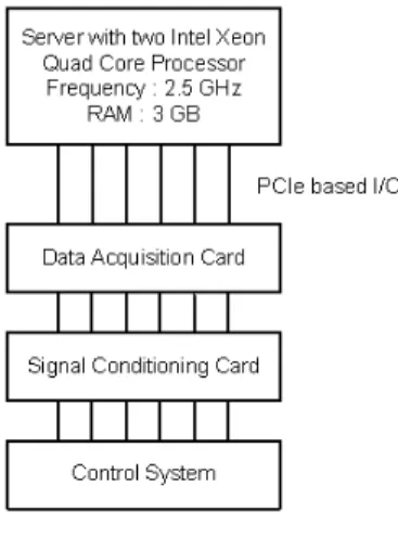
Fig. 1. The Hardware Setup
Any real-time simulation environment needs three essential components: a mechanism to accept a description of the system to be simulated, a digital hardware platform to carry out the simulation, and real-time software to manage the simulation. This paper addresses these three issues from the viewpoint of an educational laboratory setup. In the setup described in this paper, the system description mechanism is provided by a public-domain circuit simulator, SEQUEL [10].
The digital hardware platform is an off-the-shelf computer having two 4-core Intel Xeon processors running at 2.5 GHz,
and having 3.1 GB RAM. The operating system used is QNX Neutrino 6.4.0 RTOS with a Symmetrical Multi-Processing (SMP) instrumented microkernel, which permits the creation and scheduling of parallel threads on multiple cores. In addi- tion, a standard PCI-E I/O card is placed in the computer to provide external interface capability for HIL simulation. The hardware setup of the system is pictorially depicted in Fig. 1.
This report is structured in three parts: a brief description of the System Design Entry, followed by real-time execution organization, and few power electronic system simulation example with experimental results. It also includes an analysis of the timing issues that are relevant to the use of a RTOS on multi-core processors.
II. SYSTEMDESIGNENTRY
A real-time simulator for power electronic systems should have a system design entry mechanism that accepts a high level description of the circuit and system to be simulated.
This is essential to make the simulator easy to use. Further, it is also very important that the high level design entry and the subsequent translation to real-time executable code should entail the minimum overhead in the code execution time.
Several commercially available packages have sophisticated design entry mechanisms, but produce executable code that is not optimum.
The simulator described in this paper uses the public- domain circuit simulator SEQUEL [10] as its design entry front end. SEQUEL is a fully fledged off-line circuit simulator with an extensive library of power electronic and power system components. The library can be extended by users to incorporate new system components. This off-line simulator has the enhanced capability of accepting high level system descriptions for real-time simulation. The organization of the real-time code generation mechanism is shown in Fig.2.
Fig. 2. Real Time Simulator Setup
As shown in Fig.2, SEQUEL takes the system description from a high-level descriptor file, parses it and generates an intermediate descriptor file which is used to initialize the real-time system simulation. The intermediate file contains information on the various scalars, matrices and pointers used in the real time simulation. The information on the numerical integration method and the time step is also included in the intermediate file. The real-time simulator described in this paper allows users to choose either the Backward Euler method or the Trapezoidal Rule (both with fixed time step)
for numerical integration. The RTOS schedules the parallel threads for execution on multiple cores.
The process of real-time system initialization makes use of a set of fixed subroutines and a set of real-time library elements and creates parallel threads of execution. Users can extend the real-time element library to include their own elements, thus making the process of design entry very flexible for an educational laboratory. The real-time elements fall in two categories: (a) electrical elements such as resistors, inductors, voltage sources, switches and electric machines, and (b) general elements such as lag, proportional-integral (PI) controllers, waveform generators and pulse-width modulation (PWM) blocks.
III. PARALLELEXECUTION ONMULTIPLECORES
POSIX threads [11] are used for parallel execution of the real-time simulation on multiple cores. The creation of threads for parallel execution entails certain tradeoffs. Thread creation has timing overheads, hence threads should be created only for those tasks which are computationally intensive. A new thread should be created if and only if, thread creation and mainte- nance time is much less then the task to be accomplished by that thread. Further, in this simulator, threads are created before the real-time execution loop starts, and destroyed only when the simulation stops. The integration time step is derived from the timer interrupt of the computer’s system timer.
A detailed timing analysis of different segments of the simulator was done to find out where parallelism can be implemented most effectively. It was found that the segment pertaining to system matrix calculations for the next iteration, which involves matrix multiplication, is an operation that can be parallelized most effectively. Hence majority of the threads for parallel execution were created for matrix multiplication.
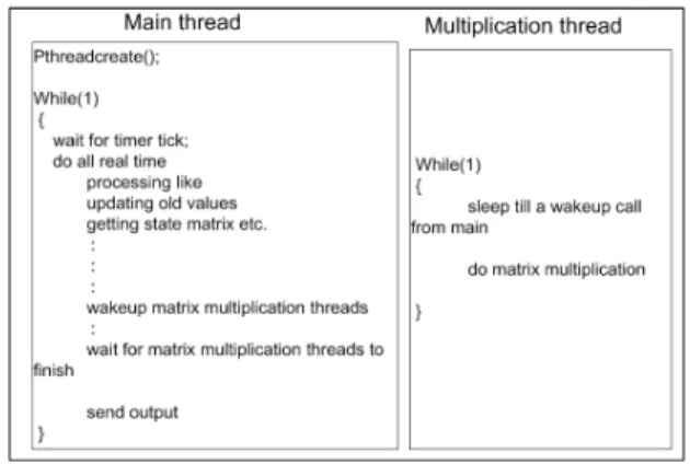
For this, threads should be created depending on the number of cores available in the system. The system described in this paper has eight available processor cores. Of these, one core was dedicated to the main thread. Seven other cores are available for matrix multiplication threads. These threads are shown schematically in Fig.3.
Fig. 3. Scheme for Parallelism
Each thread waits till a wakeup call from the main thread, for doing its share of the computation. The main thread
does all the processing associated with the individual circuit elements. When matrix multiplication is required, the main thread wakeup matrix multiplication threads waiting for its signal. The main thread itself waits till all matrix multiplication threads are finished. When matrix multiplication is done the execution moves ahead in the main thread. The main thread writes the output vector to memory and waits for next timer tick to start a new iteration cycle. This output vector in memory can be routed through a DAC for a real time input to some controller or to oscilloscope. It can also be saved for non real time analysis.
We need synchronization at two places, one for triggering the parallel threads and other to end wait of main thread.
Several synchronization schemes were tested on RT-SEQUEL.
Two of them are presented here:
A. Implementation using condvar, broadcast and barrier with BMP
This implementation uses a.) condvar which is a condition variable, to block a thread within a critical section until some condition is satisfied. These condvars must always be included within mutex lock and unlock. We are using them for making parallel threads to wait, b.) broadcast, which on a condvar unblocks all threads currently blocked on the condition variable. Hence we have used it to unblock parallel matrix multiplication threads, c.) barrier, it is a synchronization mechanism that lets several cooperating threads meet at a point, forcing them to wait at a specific point until all have finished before any one thread can continue. We have used it for making the main thread wait untill parallel matrix multiplication threads are done. Fig. 4 shows implementation of the above scheme. We have used the Bound Multiprocessing (BMP), that is the affinity of the threads is set to some specific CPU core. So they don’t switch from one CPU core to another.
Fig. 4. Implementation with condvar and barrier for BMP
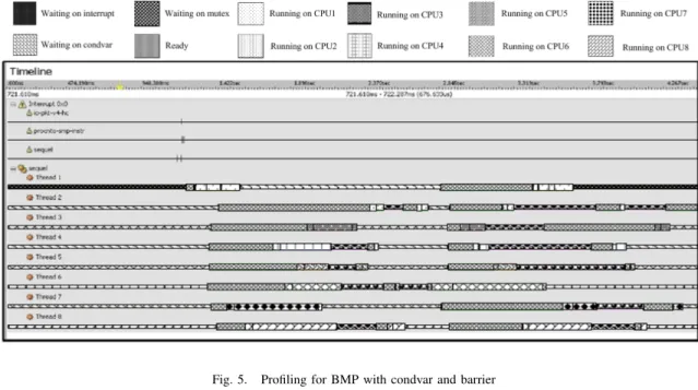
Profiling result for a single iteration is shown in Fig. 5.
It can be seen in the figure that the actual computation time is much less then the time spent by each thread in mutex and resolving synchrinizaton issues. The time taken by each iteration is also very high. It is due to the fact that microkernel has to schedule itself on each core before the thread can come out of mutex wait state on that particular core. But since we have used BMP approach, the CPU migration is very less.
Hence it can be inferred that the above synchronization
scheme is not very effective, since most of the time is spent in resolving synchronization issues and hence results in many kernel calls. Because of the involvement of mutexes, the time spent in waiting is not very predictable and a predictable time is utmost important in any real time system.
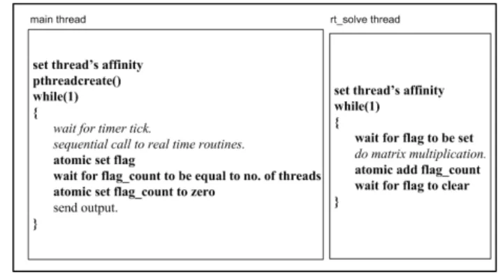
B. Implementation using Atomic updation with BMP
Above implementation for synchronization involve signif- icant kernel calls and kernel can run at a time only on one core. Hence most of the time threads are ready but not running and hence are not able to use the benefits of parallel hardware. Hence for the next implementation we have used atomic opeartions [12]. They don’t need any kernel interference. Atomic operations are used to perform a short operation (such as incrementing a variable) with the guarantee that the operation will perform atomically – i.e. the operation won’t be preempted by another thread or ISR (Interrupt Service Routine). The atomic implementation of the system is implemented as shown in the Fig. 6.
Fig. 6. Implementation using Atomic Updation for BMP
All parallel matrix multiplication threads continuously poll for the f lag variable to set in a tight loop. When the f lag is set by the main thread, parallel threads do the matrix mul- tiplication whereas, the main thread polls for the f lag join variable to be equal to num of threads, which is number of parallel threads. Each parallel thread after finishing its part of computation increment num of threads, when all are done, the num of threads become equals to number of parallel threads. The main thread exits from its tight loop, clears the f lag and f lag join variable and continue to produce output and wait for another iteration. Results are shown in fig. 7.
The time taken has drastically reduced. Number of kernel calls has also reduced. We can see that threads 2, 3 and 4 are always busy, they are never scheduled or migrated. They are either in the tight loop checking for the f lag or doing the computation. Hence no kernel calls for them. Being a BMP implementation, thread 1 also don’t migrates from one core to another.
This seems to be a workable implementation, but as can be seen that it loads the CPU a lot. CPU cores are just continuously testing for a variable to be set or reset. This is wastage of resources, but for real time application which needs to 100% predictable, this is a good implementation. If
Fig. 5. Profiling for BMP with condvar and barrier
Fig. 7. Profiling for BMP with Atomic Updation
we have sufficient numbers of cores to spare, then we can keep some cores to be in tight loop, whereas other cores can still be scheduled by the microkernel.
IV. EXPERIMENTALRESULTS
To demonstrate the efficiency of the real-time simulation setup described above, two examples were tested. The system description for the examples was generated in a high-level descriptor file. The threads for real-time parallel execution were created as described above.
A. Example 1 : A scalar controlled induction motor drive The schematic diagram of the example 1 is given in Fig.
8[13]. The real-time library contains all the elements needed for the simulation. These elements include the induction motor transient model, the PWM voltage generation block, the PI controller and various summing and multiplying blocks. The inverter switching frequency was 1 kHz. The Backward Euler integration method with a time step of 50 µs was used for this simulation.
Following plots were obtained in real-time for the motor speed. Fig. 9 shows the speed response of the motor under real-time simulation, when the speed setting is changed from
Fig. 8. Block Diagram of v/f control of Induction Motor
100 rad/sec to 150 rad/sec, and then down to 70 rad/sec. The motor rated speed is 157 rad/sec, corresponding to 1500 rpm.
The motor was not loaded. Fig. 10. shows the response of the motor speed for a change in the load torque from 0 to the rated torque of 1.98 kNm.
Fig. 9. Speed Response of Motor with change in speed settings
Fig. 10. Speed Response of Motor with change load torque
Three threads were used in parallel for multiplying the
39X39 system matrix with the 39X1 system vector. One thread was used to implement the main loop of the timer interrupt subroutine. These threads were run at the highest priority permitted by the RTOS. The total time needed to execute each time step iteration with parallel threads was 9µs B. Example 2 : Three phase inverter with RL Load
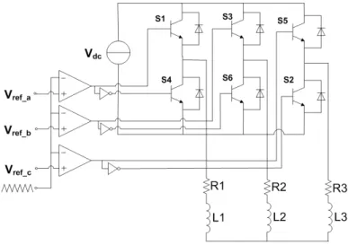
The schematic diagram of the example 2 is given in Fig. 11.
Real time elements used are the real time model of switches to make the inverter circuit, the sine triangle modulation block, resistance and inductors. The triangle wave frequency in sine triangle modulation was 1 kHz. The Backward Euler integration method with a time step of 50 µs was used for this simulation.
Fig. 11. Three phase inverter with RL Load
Following plots were obtained in real-time for the inverter and Load current in three phase.
Fig. 12. Inverter and Load Current
Three threads were used in parallel for multiplying the 23X23 system matrix with the 23X1 system vector. One thread was used to implement the main loop of the timer interrupt subroutine. These threads were run at the highest
priority permitted by the RTOS. The total time needed to execute each time step iteration with parallel threads was 7µs
V. CONCLUSION
This paper describes a low-cost real-time simulation setup that makes use of off-the-shelf multi-core computers for the simulation of power electronic systems. The real-time simula- tor uses public domain software for the real-time operating system, and for the system design entry front end. The hardware and software are suitable for use in setting up an educational laboratory for the real-time simulation of power electronic systems.
Evolution of actual parallelism in the form of multi core processors and their support in RTOS promises efficient implementation of Hardware in loop real time simulation even for most time critical applications. Hence careful study, decomposition and implementation of the parallel threads is important to gain the speedup from the parallel hardware.
Mere identifying and implementing parallelism will not suffice, because parallelism has its own overheads as well.
It should be implemented for computation intensive func- tions only, where computation time is greater then thread creation and maintenance time. So such areas should be identified wisely and degree of parallelism should be decided accordingly. Various paradigms for parallel programming and synchronization among threads are available. They should be chosen wisely depending on the system at hand. For real time system, the selection should guarantee 100% predictability.
REFERENCES
[1] A. Boukerche; S. K. Das, ”Distributed Interactive and Real-time Simu- lations”, Distributed Interactive Simulation and Real Time Applications, 1997., First International Workshop on , vol., no., pp.3-5, 9-10 Jan 1997 [2] K. J. Astrom, H. Elmqvist, S. E. Mattsson, ”Evolution of Continuous- Time Modeling and Simulation”, The 12th European Simulation Multi- conference, ESM’98, June 16-19, 1998, Manchester, UK
[3] L. Pollini, M. Innocenti, ”A Synthetic Environment for Dynamic Systems Control and Distributed Simulation”, IEEE Control Systems Magazine, April 2000, pp. 49-61.
[4] P. Baracos, G. Murere, C. A. Rabbath, W. Jin, ”Enabling PC-based HIL simulation for automotive applications”, Electric Machines and Drives Conference, 2001. IEMDC 2001. IEEE International , vol., no., pp.721- 729, 2001
[5] A. G. Jack, D. J. Atkinson, H. J. Slater, ”Real-time emulation for power equipment development. Part 1: Real-time simulation”, IEE Proc.-Ekctr.
Power Appl., Vol 145, No. 2, March I998, IEE Proceedings online no.
19981753
[6] R. Champagne, L. Dessaint, G. Sybille, B. Khodabakhchian, ”An approach for real-time simulation of electric drives”, Electrical and Computer Engineering, 2000 Canadian Conferenceon Volume 1, 7-10 March 2000 Page(s) : 340 - 344 vol.1
[7] T. Berry, A. R. Daniels, R. W. Dunn, ”Real time simulation of power system transient behavior”, Power System Monitoring and Control, 1991., Third International Conference on , vol., no., pp.122-127, 26- 28 Jun 1991
[8] R. Crosbie, J. Zenor, R. Bednar, D. Word, N. Hingorani, T. Ericsen,
”High-Speed, scalable, real-time simulation using DSP arrays”, Parallel and Distributed Simulation, 2004. PADS 2004. 18th Workshop on 16-19 May 2004, Page(s):52 - 59
[9] O. Balci, R. P. Sadowski, R. E. Nance, ”Toward Real Time Simulation : Prototyping of a large scale Parallel Ground Target Simulation”, Simulation Conference, 1990. Proceedings., Winter 9-12 Dec. 1990 Page(s):870 - 877
[10] M. B. Patil, S. P. Das, A. Joshi, M. Chandorkar, ”A new public-domain simulator for power electronic circuits”, Education, IEEE Transactions on Volume 45, Issue 1, Feb. 2002 Page(s):79 - 85
[11] IEEE Guide for Portable Operating System, IEEE Std 1003, (2002).
[12] QNX Neutrino System Architecture Documenta- tion for release 6.3.0 or later. Available online at http://www.qnx.com/download/download/14695/sys arch.pdf
[13] W. Leonhard, Control of Electrical Drives, 3rd Edition, Springer Inter- national Edition, Page 242-245.