國立臺灣大學電機資訊學院資訊工程學系 碩士論文
Department of Computer Science and Information Engineering College of Electrical Engineering and Computer Science
National Taiwan University Master Thesis
應用於控制器空間的動畫傳遞法 Rig-Space Motion Retargeting
胡林銓 Lin-Chuan Hu
指導教授:莊永裕博士 Advisor: Yung-Yu Chuang, Ph.D.
中華民國 102 年 6 月
June, 2013
致謝
在短短兩年的碩士生涯裡,無論是在課業上或研究上,我都受到了 許許多多不同的人的幫助,沒有他們的幫忙,很難想像我是否還能夠 如此順利的熬過這幾個學期。尤其是在最後這兵荒馬亂的半年裡,從 一開始的想碩論題目到之後的研究問題、解決問題、撰寫論文,乃至 於口試。能夠順利渡過這些難關,完成此篇論文,我需要感謝的人真 得是有太多、太多了。
首先,我要感謝的是我的指導教授莊永裕老師,感謝老師在這兩年 裡,給與我指導,讓我無論是在研究或是報告方面,都能隨時隨地學 到許多不同的知識,改進自己的缺點。此外,也感謝老師平時幽默風 趣的說話風格,在這兩年時光裡,帶給了我很多意想不到的歡樂。
接下來,我要感謝的是博班的 winble 學長,從碩一的產學合作案 開始到之後的碩論,感謝學長不遺餘力的幫助及指導,無論我提出什 麼問題,都會仔細地回答。此外,謝謝學長願意每個星期花時間和我 一起討論研究,時常給予我不同的建議、想法。乃至於最後要口試的
時候,還幫我修改論文、修正報告的投影片 · · · 等。嚴格說起來,
假如沒有學長的幫助的話,我是無法順利完成這篇論文的。
最後,感謝這兩年來所有幫助過我的人以及 CMLAB 的同學、學 長。由於你們的陪伴,我的碩士生活過得非常得充實。在 CMLAB 度 過的這段時光,肯定會是我這輩子最寶貴的記憶之一。
胡林銓 謹誌 中華民國一百零二年六月
摘要
為了幫助動畫師提升製作動畫的效率,本論文提出了一個全新的 動畫傳遞架構,讓動畫師能夠將一來源動畫 (Source animation) 的角 色控制器 (Rig) 參數自動地傳遞到目標模型 (Target model) 上,而此 參數還可進一步幫助動畫師對此新產生的動畫,進行修正以及更進一 步的變化應用。所謂的角色控制器,是一種提供動畫師更好控制模型 動作的系統工具,廣泛地被使用於目前動畫產業;然而,由於其高複 雜度,現有的動畫傳遞方法皆選擇跳過此部分,直接使用模型網格以 及過度簡化的模型骨架,因此產生的結果無法提供予動畫師使用、調 整及應用,也造成此類方法始終無法被動畫產業所實用。針對此限制 與缺陷,我們提出一套新的架構,其中主要可分為三個步驟:首先在
「動作傳遞」部分,為了解決來源與目標模型間,模型拓普及角色控制 器架構皆不相同的情況,我們採取將來源動畫形變 (Deformation) 傳 遞給目標模型的方式,以此計算出每個幀 (Frame) 時目標模型應有的 對應動作。接著,我們便可藉由前一步所計算出的目標模型動作進行
「角色控制器參數重建」,以得到在此動作下最符合動畫師設定習慣的 參數。最後,我們還可協助動畫師進一步「完善目標動畫」,動畫師可 藉由微調某動作的一部分參數,進而改善整段目標動畫,使結果更符 合業界的標準。由於本方法於傳遞動畫的過程當中,考量了角色控制 器對於模型動作的影響以及動畫師的設定習慣,所以最後產出的目標 動畫可受動畫師自由地控制與調整,改善了傳統動畫傳遞方法的限制。
此外,本架構可適用於各種不同的角色控制器系統,具有相當大的彈 性,大幅提升將動畫傳遞應用於實際產業的潛力。
關鍵字: 角色控制器, 動畫傳遞, 形變, 動畫, 幀
Abstract
In this paper, we present a novel framework for transferring the ani- mation data (rig parameters) from a source animation model to a target static one. Moreover, in order to effectively satisfy user needs, our sys- tem provide a mechanism for allowing animators to further refine the animation. In industry, the character rig is an essential digital handle that animators common use to control the model into a desired pose.
However, because of its staggering complexity, most previous retargting methods only transfer mesh deformations or joint parameters rather than passing the rig parameters. Thus, it is difficult for animators to work on the retargeted animations. To resolve this limitation, a novel frame- work is proposed. First, due to different topologies and rigs between models, we apply motion transfer to deform target model mimicking the source motion. Next, we recover the target rig parameters according to the following properties: (1) the resultant animation resembles the source animation and (2) the rig parameters match the artist’s editing conventions. Finally, animators could further adjust the produced rig parameters and the changes will be effectively propagated throughout the whole animation. Our approach generates editable rig parameters of target animations and shows its potential for motion retargeting in industry.
Keywords: Motion retargeting, rig, animation. topology.
Contents
致謝 ii
摘要 iii
Abstract v
1 Introduction 1
2 Related work 5
2.1 Motion Retargeting . . . 5 2.2 Rigging . . . 7
3 Method 9
3.1 Motion transfer . . . 10 3.2 Rig parameter recovery . . . 12 3.3 Motion refinement . . . 15
4 Results and discussions 19
5 Conclusion and Future Work 28
Bibliography 29
List of Figures
1.1 Two different definitions on rig. The rig only means a simplified skele- ton in most academic papers. However, in industry, the rig consists of numerous controllers and the skeleton. . . 1
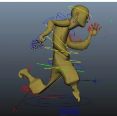
1.2 An example of the rig structure. From the left to the right are the model’s mesh, skeleton, rig and the magnification for some controllers of its rig. For the operation convenience of artists, controllers are designed with various functions, shapes and manipulation methods, like cars for the sole of foot (top right) and rings for the shoulders (bottom right). . . 2
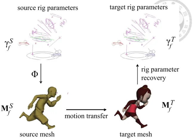
3.1 The core idea of the proposed approach. Given a source model, a source animation and a target model, our system finds a set of rig parameters to produce the target animation. . . 10
3.2 Flow of the proposed system. We first use motion transfer to produce target motions that performs similar with source animation. Next, we recover proper rig parameters that would result in a mesh similar to the target motion we just obtained. Finally, the motion refinement process is provided for user to refine the target animation through resultant rig parameters. . . 11
3.3 A example of the strangely contorted mesh. . . 14
3.4 An example of user refinement on the angle of right leg angle in re- sultant animation. Left column is the pose without user adjustment.
Middle column is the pose after first adjusting operation. Right col- umn is the final pose after user refinement with twice operations.
Bottom row: magnification of the right leg during the refinement. . . 16
3.5 A timeline example of the resultant animation. We use E5, Es to propagate the refinements of the 6th frame to 7th frame ∼ 14th frame. Similarly, we use E6, Eb to propagate the adjustments to 2nd frame ∼ 5th frame. . . 17
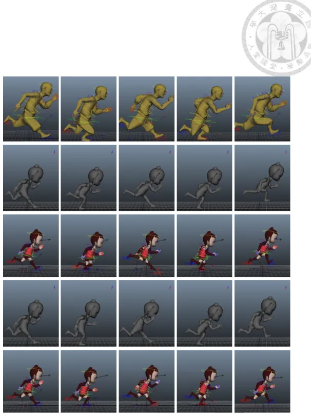
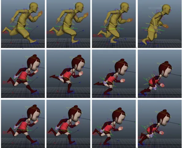
4.1 Step results. Top row: source motions. Seccond row: results in motion transfer step. Third row: results in rig parameter recovery step. Fourth row: refined results in motion transfer step. Bottom row: refined results in rig parameter recovery step. . . 22
4.2 The comparison of adding temporal smoothness in motion transfer.
Top row: source motions. Middle row: original deformed results without temporal smoothness. Bottom row: the results with tempo- ral smoothness. . . 23
4.3 The impacts of different energy terms in rig parameter recovery. In this example, we focus on the right shank controller (the one in a blue car shape) and the spine skeleton (the red line in the fourth column). Top row: source motions. Second row: results using the energy function with only Em. Third row: results using the energy function with only Em and Eu. Forth row: results using the energy function with only Em and Es. Bottom row: results using the energy function with all three terms. . . 24
4.4 Motion refinement. Top row: source motions. Second row: results without refinement. Third row: refined results after editing three keyframes. The artificial animation created by artists is shown on the bottom row as a comparison reference. On the rightmost column, we show how the left leg is improved through user refinements. . . 25 4.5 Another motion retargeting example of the walking cycle animation.
Top row: source motions. Middle row: results without refinement.
Bottom row: refined results after editing three keyframes. . . 26 4.6 Motion retargeting example of vastly different models. In this case,
we use two extremely different artist-created models, Arhat and Flour- Sack, as our input. Top row: source motions. Middle row: results. . . 26 4.7 Motion retargeting example of different rigging systems. Source model
is Arhat and target model is CyclopsBoy. Top row: source motions.
Middle row: results without refinement. Bottom row: refined results after editing four keyframes. . . 27 5.1 A controller of the left leg. . . 29
List of Tables
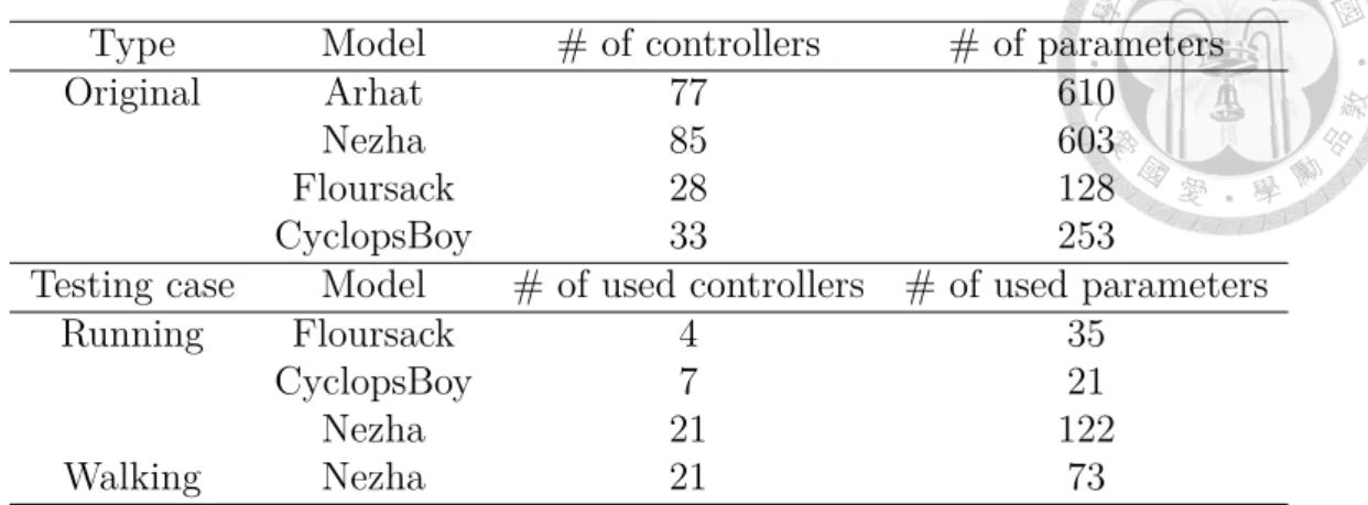
4.1 The numbers of controllers and parameters used in experiments. . . . 20
Chapter 1 Introduction
Figure 1.1: Two different definitions on rig. The rig only means a simplified skele- ton in most academic papers. However, in industry, the rig consists of numerous controllers and the skeleton.
When creating a new character animation, the animators often spend consider- able time adjusting the character into a desired pose for each keyframes. To improve their work efficiency, there are many motion retargeting techniques had been pro- posed, such as deformation transfer, skeleton-based transfer and so on. Motion
retargeting technologies help transfer animation between different models automat- ically. However, because of the staggering complexity of character rig, most existing retargeting methods only transfer mesh deformations or simplified rig information (joint parameters) rather than passing the complete rig parameters during retar- geting. This choice produces different definitions of rig as shown in Figure 1.1. In industry, the character rig is composed of numerous controllers bound to meshes and skeleton. Animators operate these controllers to adjust the character pose in each keyframe. However, in most academic papers, the rig is often reduced to an over-simplified skeleton without considering any controllers.
The traditional academic definition of rig seriously affects its practice. In in- dustry, before the 3D character model handed over to the team of animators, it requires to be bound to a system of joints and controllers. This process is known as rigging and is done by artists known as character technical directors (TDs), or riggers. Therefore, due to the usage of over-simplified skeleton, the existing motion retargeting technologies cannot work on the production pipeline.
Figure 1.2: An example of the rig structure. From the left to the right are the model’s mesh, skeleton, rig and the magnification for some controllers of its rig. For the operation convenience of artists, controllers are designed with various functions, shapes and manipulation methods, like cars for the sole of foot (top right) and rings for the shoulders (bottom right).
The industry-level model skeleton is much complicated than academic-level one, as shown in Figure 1.2. The complexity of example model is much more than tradi- tional research model. Furthermore, multiple joints are located at the same position with different types of kinematics such as IK (inverse kinematics), FK (forward kinematics) and others. Thus, in industry, characters are often animated with their
rigs. The composition of a rig is quit different from skeleton. A rig often con- sists of a large number of controllers. Each controller can manipulate several joints and vertices by a complex many-to-many mapping function. The mapping function is operated by multiple parameters defined with different scales, ranges, meanings and constraints for artists to manipulate with. Furthermore, for each controller, its name, type (like joint’s type), manipulation method and mapping function can be varied due to different rigging systems and artist’s requirements. The many-to-many characteristic (a joint or a vertex also influenced by multiple controllers) and the intricate hierarchical relationship between controllers make manipulation in the rig space very challenging. Figure 1.2 gives an example which has 85 controllers and 603 rig parameters. For the operation convenience, controllers are often designed with different functions, shapes and manipulation methods. Some controllers are even designed with very high-level semantic operations. For instance, a common controller is used to adjust the openness of a hand. While altering the parameter of this controller, all fingers of that hand are extended and flexed.
For practical motion retargeting, in this paper, we propose a novel framework that allows users to transfer the rig parameters of one animation between models with different topologies and rigs. Considering the characteristic of animation, we first improve the multi-component deformation transfer by taking temporal coher- ence into account. Then, from the deformed target model, our system recovers the rig parameters while maintaining the motions, model structure and the temporal smoothness of parameters. Finally, our system provides an efficient propagation mechanism for artists to adjust the target animation and rig parameters. Through our framework, artists can effectively obtain the transferred rig parameters that are vital to them for further refinement and adjustment.
There are four benefits in our work:
1. It is the first rig-space motion retargeting method.
2. It is compatible with production pipeline in industry.
3. It works with various models.
4. It allows users effectively refine the results.
The rest of the paper is organized as follows. In Chapter 2, we review some related work. Chapter 3 describes our retargeting method in detail. Then, the system results are demonstrated in Chapter 4. Finally, some discussion and future work are concluded in Chapter 5.
Chapter 2 Related work
2.1 Motion Retargeting
Motion Retargeting refers to methods which transfer motions between different kinematic characters. This term was first proposed by Michael Gleicher [9] in 1998.
When retargeting animations from one character to another, the most difficult parts are how to establish the correspondences between topologically different characters, and how to transfer motions between characters with heterogeneous structures. To resolve these problems, recently, several methods have been proposed, such as de- formation transfer, skeleton-based animation transfer and cage-based deformation transfer.
Deformation transfer provids a simple way to retarget motions through copying deformations from the source mesh onto the target mesh. Sumner and Popovi�c [16]
are pioneers in this subject. Their method first establishes non-bijective mapping between the source and target meshes. Then, the affine transformation matrices from the source reference pose to the source deformed poses are encoded as the linear combination of the reference vertices (vertices on the reference pose). Fi- nally, they transfer the deformations of the source deformed poses onto the target reference pose by solving a linear system and the target deformed pose is obtained accordingly. Since their introduction, many improvements have been proposed by following researchers.
Unlike Sumner and Popovi�c’s, Zayer et al. [18] build the correspondence by har- monic field matching and transfer deformation gradients through Poisson editing.
Lee et al. [11] proposed a novel framework using the segmentation method to over- come the limitation of the above deformation transfer methods: the requirement for similar reference meshes between source and target characters. Botsch et al. [6] in- troduced a method that can speed up the linear system solve because their transfer technology needs no additional vertex for each triangle. To preserve the seman- tic characteristics of the models, Baran et al. [2] established the semantic corre- spondences from several example meshes and interpolated the patch-based linear rotation-invariant coordinates of the examples when computing the transferred re- sults. Chu et al. [7] developed a method to further refine the retargeting results through interpolating several example poses.
One serious limitation of the above deformation transfer methods is that they are restricted to single-component meshes. To overcome this problem, Ben-Chen et al.
[3] introduced a spatial deformation transfer method which is suited for multi- component meshes but would lose mesh details sometimes. that is suited for re- targeting between multi-component meshes, but his framework sometimes would lose mesh details. Zhou et al. [19] addressed the same problem but chose a different way. Their method first computes the proximity pairs between components. By using these pairs and few user-specified markers, the method deforms the reference source mesh to the reference target mesh and establishes the correspondences be- tween the source and target models. Finally, to handle multi-component meshes, the method preserves the distances between components with proximity vertex pairs when transferring the source deformation onto the target models. More recently, Yoshiyasu et al. [17] developed a method to transfer deformations of the single- component source mesh onto multi-component target meshes.
Unlike deformation transfer methods that transfer surface deformations between meshes, the skeleton-based methods retarget motions through transferring the joint values (such as the angle and the position) of the source model onto the joints
of the target model. Monzani et al. [13] created the intermediate skeleton from the correspondences between the skeletons of the source and target models. Then, they retargeted movements between characters by using this intermediate skeleton.
Poirier et al. [15] proposed a method for automatically adapting existing skeletons to different characters. Recently, Feng et al. [8] introduced a novel heuristic technique to establish the correspondences between the source and target models’ complex skeletons and retargeted motions according to these correspondences. However, this technique has many restrictions.
2.2 Rigging
Rigging is a process of binding the model rig to the model mesh and defining how the mesh vertices will be influenced by the character rig. Recently, there are many researches in this area. For example, Baran et al. [1] presented a method for automatically embedding the skeleton inside the mesh when a static character mesh and a generic skeleton have been given. Li et al. [12] proposed a technique for automatically facial rigging and their results can be further refined by several example faces. Boros �an et al. [5] proposed a method for real-time automatically creating the character skeleton and binding the mesh into it when the input is only a model mesh. Bharaj et al. [4] introduced a framework to automatically create a skeleton for the model and it can be mapped to the skeleton of another character.
These researches achieve nice results; nevertheless, they cannot be applied to rigging due to the intrinsic difference. As for rigging, we find an important paper that uses the industrial definition of rigging. Hahn et al. [10] presented a method that brings the benefits of physics-based simulation to the conventional animation pipeline in the rig space. The most important benefit of their method is that it can work with any rig systems because they interpret the term rigging as a nonlinear mapping between a low-dimensional space of rig parameters and a high-dimensional surface mesh. According to this definition, they treat the rigging system as a black box so that it can work without knowing what kind of a rig system is used.
Because most motion retargeting methods mentioned above only either transfer mesh deformations (such as deformation transfer methods) or use oversimplified skeletons in their models (such as skeleton-based methods), they are not practical be used for animation production in industry. To address this problem, we propose a method that generates editable rig parameters for the motion retargering.
Chapter 3 Method
Figure 3.1 gives an overview to the proposed system. The input to our pipeline contains the source model S, the target model T and the source animation we want to transfer. Note that the model here refers to the complete model including the mesh and rigs (including controllers and the skeleton) of the model. The input source animation is represented by the rig parameters ΓS ={γ1S, γ2S, . . . , γFS} of the source model, where γfS is the rig parameter for the f -th frame and F is the number of frames in the animation. Given the source model and its rig parameters, we can obtain the meshes of the source animation MSf using the animation packages such as Maya. In addition to those models and parameters, we also require users to specify the rig parameters γ1T of the target model for the first frame. We make such a request because there are multiple combinations of parameters that could produce the same animation. Among them, some are more intuitive to edit but some are not. We need to learn from the artist about his/her preference.
With these inputs, our system first performs a motion transfer step to deform the target model so that it perform similar motions specified by the source animation.
Next, we attempt to recover the rig parameters from the deformed target meshes with two properties: motion resemblance and parameter smoothness. If artists would like to refine the produced animation, they can adjust the rig parameters at selected keyframes and the changes will be propagated to the whole animation through the motion refinement process. Note that they can easily refine the ani-
γ f S γ f T
M f S M f T
source rig parameters
source mesh target mesh
target rig parameters
motion transfer
rig parameter recovery
Φ
Figure 3.1: The core idea of the proposed approach. Given a source model, a source animation and a target model, our system finds a set of rig parameters to produce the target animation.
mation because the resultant rig parameters are intuitive to edit by controllers and match their own editing conventions. The following sections describe each step of our framework in detail.
3.1 Motion transfer
As illustrated in Figure 3.2, to transfer rig parameters of the source model to the target model, we first transfer the motion of the source animation to the target model so that the target model performs the similar motion as specified in the source animation. We call this step motion transfer. Next, given the desired mesh of the target model at each frame, we figure out the proper rig parameters which would result in a mesh similar to the desired mesh. We call this step rig parameter recovery. We will first introduce motion transfer, and rig parameter recovery will be described in the next subsection.
Figure 3.2: Flow of the proposed system. We first use motion transfer to produce target motions that performs similar with source animation. Next, we recover proper rig parameters that would result in a mesh similar to the target motion we just obtained. Finally, the motion refinement process is provided for user to refine the target animation through resultant rig parameters.
For motion transfer, we adopt the framework of the deformation transfer to obtain better stability and performance [16]. Because of the intricate hierarchical relationship of model skeletons used in industry, we adapt the deformation transfer method for multi-component objects proposed by Zhou et al. [19]. Their method is designed for single motion deformation; therefore, we extend it with a temporal smoothness term since our problem deals with animations.
Zhou et al.’s method first utilize the vertex proximity between components to build a graph representing their spatial relationship. The correspondences between source and target triangles are established by the connectivity of the graph. Finally, deformation transfer is achieved by minimizing the following energy function:
ED = w1E1+ w2E2+ w3E3+ w4E4. (3.1)
The E1 term computes the difference between transformations of the corresponding triangles in the source and target meshes. For the orphan triangles without corre- spondences in the source model, the E2 term regularizes their transformations to be close to the transformations of triangles adjacent to them. The third energy term E3 maintains the spatial relationship between components and the final term E4
uses Laplacian coordinates to preserve the surface detail for the components with- out proper correspondences in the source object. For the detailed definitions of these terms, please refer to their paper [19]. Since our method transfers the whole anima- tion rather than single pose, for maintaining the temporal coherence in the resultant animation, we add a temporal smoothness term E5 so that the transformations of triangles in current frame are close to those in the previous frame:
E5 = ∑
Ca∈C
∑
ti∈Ca
||Qfti − Qf−1ti ||2, (3.2)
where C is the target model mesh consisted of multiple components; Ca is a com- ponent of C; ti is a triangle of Ca and Qfti represents the transform of triangle ti at the frame f . There are two major functions of this temporal smoothness term E5. Firstly, it can preserve the temporal smoothness between neighboring frames.
Secondly, it can propagate the character motion style to subsequent frames from the first frame that user specified. In Chapter 4, our experiment proves that the result becomes better with the assistance of this smoothness term.
Thus, our modified energy function becomes
ED = w1E1+ w2E2+ w3E3+ w4E4+ w5E5. (3.3) For all the examples in this paper, we used the same weight setting w1 = w2 = w4 = 1.0 as their paper and w3 = 2.0 in our practice and set w5 the same as w1 for a good balance between model deformation and temporal coherence. With the proposed motion transfer method, we obtain the desired target mesh eMTf for each frame f mimicking the motion of source model.
3.2 Rig parameter recovery
The core component of our system is rig parameter recovery which finds out a set of rig parameters ΓT ={γ1T, γ2T, . . . , γFT} for the target model so that the resultant
meshes resemble the desired meshes eMTf obtained in the motion transfer step.
To handle the complex rig space and various rigging systems, similar to Hahn et al. [10], we treat the entire rig mapping process Φ as a black box. For the target model T , given the rig parameter γfT at the frame f , the black box return the corresponding mesh
MTf = Φ(T, γTf) (3.4)
By hiding dozens of complex non-linear rig mapping functions behind the black box, our approach is versatile and can be used with various rigging systems. In this pa- per, we use the popular industrial animation tool - Maya as the black box to obtain the corresponding meshes.
Energy function
We estimate the rig parameters γf for the target model at the frame f by mini- mizing the following energy function:
EP(γf) = Em(γf) + wuEu(γf) + wsEs(γf), (3.5)
where Em, Eu, Es are respectively the energy terms for maintaining mesh similarity to the desired mesh, undeformability of model structure and temporal coherence of the mapped target meshes. For all examples in this paper, wu = 5,000 for treating Eu as a hard constraint, and ws = 0.01.
The first term Em ensures the selected rig parameters maintain the fidelity of the resultant mesh to the desired mesh eMTf. It is defined as:
Em(γf) =
|M∑Tf| i=1
∥vf iT − evf iT∥2, (3.6)
where vTf i is the i-th vertex of the resultant target mesh MTf = Φ(T, γf) at the f -th frame andevf iT is the i-th vertex of the desired mesh eMTf at the f -th frame.
Figure 3.3: A example of the strangely contorted mesh.
The undeformability term Eu helps maintain the model structure by preserving the skeleton lengths in the mapped target meshes:
Eu(γf) =
∑|K|
i=1
(lTf i− ˜lTi
)2
, (3.7)
where K is the set of all bones; lTf i refers to the length of the i-th bone of the induced target mesh at the frame f and ˜liT is the length of the i-th bone of the reference target mesh (the mesh that artists used to specify the correspondences for deformation transfer, usually the mesh of the first frame). With this enery term, we can ensure our resultant target mesh without any strange contortion (Figure 3.3 shows an example of the strangely contorted mesh).
We usually assign a large value to the weight wu of this undeformability term to regard it as a hard constraint for maintaining physical structure of the model.
However, it could be set as a smaller value for some controllers if the artist would like to allow deformation of the model.
The temporal smoothness term Es is used to maintain the temporal coherence of rig parameters:
Es(γf) =∥γfT − γfT−1∥2 (3.8) where γfT and γfT−1represent the rig parameter vectors in the f -th and the (f−1)-th frame. As mentioned before, there are multiple combinations of rig parameters which could produce the same animation. Therefore, similar to the temporal smoothness term in the motion transfer step, we apply the term Es to achieve the ability of tem-
poral smoothness preservation and motion propagation. In addition, this term is able to avoid mapping meshes with rig parameters that are impossible to edit. Our system requires artists to assign proper target rig parameters (which match their editing conventions) and uses the temporal smoothness term to propagate them throughout the animation.
Optimization
For optimizing the energy function defined in Equation 3.5, we adopt the Newton- Raphson minimization scheme to find the best rig parameters γfT for f = 2, 3, . . . , F
γfT = arg min
γf EP(γf) (3.9)
for its good performance with fewer calls to the expensive black box. Since we cannot obtain the analytic Jacobians of the rigs, we choose to use the super-linearly conver- gent Broyden-Fletcher-Goldfarb-Shanno (BFGS) [14] method for the optimization.
3.3 Motion refinement
After the rig parameter recovery, we obtain a set of rig parameters ΓT = {γ1T, γ2T, . . . , γFT} for the target model satisfying that (1) the animation resembles the source animation and (2) the rig parameters match the artist’s editing con- ventions. For minor 3D characters, such rig parameters are usually good enough.
Nevertheless, for main characters which usually require high-quality performance, the artists might want to tweak parameters to enrich their styles or to fix errors introduced during the optimization processes. Our system allows users to further refine the animation by using controllers in their favorite rigging system to adjust rig parameters at selected frames. For instance, as show in Figure 3.4. When ani- mators don’t like the angle of right leg in resultant animation , they can modify the leg controllers to obtain satisfied pose at selected frame. To reduce time and effort,
Figure 3.4: An example of user refinement on the angle of right leg angle in resultant animation. Left column is the pose without user adjustment. Middle column is the pose after first adjusting operation. Right column is the final pose after user refinement with twice operations. Bottom row: magnification of the right leg during the refinement.
each refinement will be automatically propagated to the whole animation through optimization. In our experiments, artists usually achieve satisfied results after a couple of iterations.
For propagating user’s refinement, our optimization takes into account all frames that artist has edited and named them as keyframes. Note that initially the only keyframe is the first frame. Assume that after editing we have keyframes K1, K2,
…, Kn, the energy functions for motion transfer and rig parameter recovery are both modified to take advantage of these added keyframes. In the original formulation, we can only propagate forward since the only keyframe is the first frame. With more keyframes, we can propagate both forward and backward. Thus, we add backward propagation terms into Equation 3.3 and Equation 3.5. The energy ED becomes:
ED = w1E1+ w2E2+ w3E3 + w4E4
+w5· α · E5+ w6· (1 − α) · E6, (3.10)
where the new term E6 is the backward smoothness term for triangle transforms defined as
E6 = ∑
Ta∈T
∑
ti∈Ta
||Qfti− Qf +1ti ||2. (3.11)
Figure 3.5: A timeline example of the resultant animation. We use E5, Es to propa- gate the refinements of the 6th frame to 7th frame∼ 14th frame. Similarly, we use E6, Eb to propagate the adjustments to 2nd frame ∼ 5th frame.
We set w6 = 1.0 to balance the influence of keyframes in the forward and backward direction and use the temporal distance ratio α to weight the influence of two closest keyframes at both directions. Assume that kf and kb are the closest keyframes at the forward and backward direction respectively. Then α is defined as the ratio of backward distance to the distance between two keyframes kkb−f
b−kf. Similarly, for rig parameter recovery, we modify the energy EP as
EP(γf) =Em(γf) + wuEu(γf) + ws· α · Es(γf)
+ wb· (1 − α) · Eb(γf), (3.12)
where wb = ws. α is defined similarly and the backward temporal smoothness term is defined as
Es(γf) = ∥γfT − γf +1T ∥2. (3.13)
For example, if the 6th frame of the resultant animation in the first iteration has been refined (Figure 3.5). In next iteration, during the motion transfer step, we can use temporal smoothness term E5 o propagate these changes to subsequent frames (e.g. 7th frame, 8th frame,· · · , etc.) and use backward temporal smoothness term E6 to propagate the refinements to previous frames (e.g. 2nd frame, 3rd frame,
· · · , 5th frame .). Similarly, during the Parameter Recovery step, we can propagate adjustments to both subsequent frames and previous frames with term Es and term Eb, respectively. Finally, all frames of the resultant animation are refined by single adjustment of 6th frame.
Chapter 4
Results and discussions
The proposed framework provides a useful tool that assists artists to transfer rig parameters of an animation between different models. We used four artist- created models, Arhat, Nezha, FlourSack and CyclopsBoy, in our experiments. A two artist-created animations of Arhat were used as source animations. The numbers of controllers and parameters involved in our experiments are listed in Table 4.1.
There are often numerous controllers and parameters of a model. However, under the consideration of system efficiency, accuracy and the artist’s conventions, artist can choose the really relevant ones which may be used in this animation beforehand.
For example, as show in the Table 4.1. The number of parameters of Nezha is 603, but only 122 parameters should be involved in the running case.
As mentioned in Chapter 3, during the Motion Transfer step, our system firstly predict the desired target meshes according to the source motions. Next, the target rig parameters is recovered to fit the predicted mesh while preserving the undeforma- bility of model structure and the temporal smoothness of parameters in Pararmeter Recovery step. Finally, when artist refines the resultant animation, the previous steps are re-executed and these changes will be propagated throughout the whole animation. The results of each steps are shown in Figure 4.1
Figure 4.2 demonstrates the effects of using temporal smoothness in motion transfer. With the assistance of time coherence term, the target animation becomes smoother and closer to the source motions. In addition, the information of the
Table 4.1: The numbers of controllers and parameters used in experiments.
Type Model # of controllers # of parameters
Original Arhat 77 610
Nezha 85 603
Floursack 28 128
CyclopsBoy 33 253
Testing case Model # of used controllers # of used parameters
Running Floursack 4 35
CyclopsBoy 7 21
Nezha 21 122
Walking Nezha 21 73
user-specified first frame is clearly propagated to the following frames. Substantial improvements can be observed on the postures of the back and legs in the target motion.
Figure 4.3 demonstrates the influences of energy terms in rig parameter recovery.
Without the constraints of undeformability term Eu, the mapped mesh could be skewed badly as the skewed spine shown in the rightmost column of the second row.
Although the temporal coherence term Es slightly degrade the motion fidelity, it effectively maintains the stability of rig parameters which is important to animators for further editing. The forth row shows that the right shank controller (in a blue car shape) is better transferred with the use of Es. The temporal smoothness can also help maintain the model structure in some degree. For example, the spin is preserved by the temporal smoothness even though we do not use Eu in the forth row. Finally, the inclusion of all three energy terms achieves the best stability and performance as shown in the last row.
Figure 4.4 demonstrates the improvement of using motion refinement. After adding three keyframes, the back and leg postures can be clearly improved. Through the refinement, the over incline degree of model’s back is fixed and the bending posture of its left leg become more nature. In our experiments, users can obtain satisfied results by editing at most three to five keyframes with only a few operations.
It shows that the resultant rig parameters are editable and our proposed motion refinement process can effectively propagate user’s editing which reduce much user’s
effort.
Figure 4.5 shows another example of a walking animation. Since motions in this sequence are slower and more subtle, it is more difficult than the running animation.
For such challenging task, our method can still produce acceptable results.
To prove the ability of our framework to work smoothly with various models and different rigging systems, we use two extremely different artist-created models, Arhat and FlourSack, as our input. The artist-created running cycle animation of Arhat is used as source animation. As show in Figure 4.6. in spite of the large difference in rig structure and model topology, our system can still work well and produce a nice running cycle animation of FlourSack. Another case is shown in Figure 4.6. We test more case as show in Figure 4.7. In this example, we use Arhat and CyclopsBoy as our source and target models, and retarget the running animation from Arhat to CyclopsBoy.
Figure 4.1: Step results. Top row: source motions. Seccond row: results in motion transfer step. Third row: results in rig parameter recovery step. Fourth row: refined results in motion transfer step. Bottom row: refined results in rig parameter recovery step.
Figure 4.2: The comparison of adding temporal smoothness in motion transfer.
Top row: source motions. Middle row: original deformed results without temporal smoothness. Bottom row: the results with temporal smoothness.
Figure 4.3: The impacts of different energy terms in rig parameter recovery. In this example, we focus on the right shank controller (the one in a blue car shape) and the spine skeleton (the red line in the fourth column). Top row: source motions.
Second row: results using the energy function with only Em. Third row: results using the energy function with only Em and Eu. Forth row: results using the energy function with only Em and Es. Bottom row: results using the energy function with all three terms.
Figure 4.4: Motion refinement. Top row: source motions. Second row: results without refinement. Third row: refined results after editing three keyframes. The artificial animation created by artists is shown on the bottom row as a comparison reference. On the rightmost column, we show how the left leg is improved through user refinements.
Figure 4.5: Another motion retargeting example of the walking cycle animation.
Top row: source motions. Middle row: results without refinement. Bottom row:
refined results after editing three keyframes.
Figure 4.6: Motion retargeting example of vastly different models. In this case, we use two extremely different artist-created models, Arhat and FlourSack, as our input. Top row: source motions. Middle row: results.
Figure 4.7: Motion retargeting example of different rigging systems. Source model is Arhat and target model is CyclopsBoy. Top row: source motions. Middle row:
results without refinement. Bottom row: refined results after editing four keyframes.
Chapter 5
Conclusion and Future Work
This paper proposes a system that allows animators to obtain editable rig pa- rameters for motion retargeting. It is compatible with production pipeline and can be used with standard animation packages, which shows benefit for industry ap- plication. Our method treats the complex rig mapping functions as a black box and iteratively applies it in the optimization to reconstruct the target rig parame- ters. By this mechanism, our framework can be applied to various rigging systems, hence, increases much flexibility. Moreover, in addition to the preservation of target model shape, we also maintain the undeformability of model structure and temporal smoothness of rig parameters in the optimization process. Finally, a propagation mechanism is provided to help artists further refine the results. The experiments demonstrate the stability and effectiveness of our framework and show our potential to practice in industry.
Although satisfied results are obtain in our system, there are several limitations can be improved. First, the computational bottleneck of our method is caused by the black box communication to Maya. When solving the nonlinear energy function of parameter reconstruction, we need to transfer data between Maya and our system numerous times, which causes our system beneath real-time and the performance to become inversely proportional to the numbers of the rig parameters. Next, the method to achieve the correspondence between models can be further improved for efficiency. In addition, since our algorithm is design on polygon model, the
Figure 5.1: A controller of the left leg.
application or transformation on NURBS model can be further extended. Besides, in the rig parameter reconstruction, an automatic parameter chooser can improve our result. An accurate estimation of parameters used in each frame can reduce the chaos brought by the numerous possible combinations of rig parameters. Figure 5.1 demonstrates an example that the left tiptoe of target model is over-bended due to the usage of improper combination of rig parameters. Finally, to improve the system stability, we can invite artists to experiment more types of rig and more devise motions.
Bibliography
[1] I. Baran and J. Popovic. Automatic rigging and animation of 3d characters.
ACM Trans. Graph., 26(3):72, 2007.
[2] I. Baran, D. Vlasic, E. Grinspun, and J. Popovic. Semantic deformation trans- fer. ACM Trans. Graph.(Proceedings of SIGGRAPH 2009), 28(3), 2009.
[3] M. Ben-Chen, O. Weber, and C. Gotsman. Spatial deformation transfer. In Symposium on Computer Animation, pages 67–74, 2009.
[4] G. Bharaj, T. Thormählen, H.-P. Seidel, and C. Theobalt. Automatically rig- ging multi-component characters. Comput. Graph. Forum, 31(2):755–764, 2012.
[5] P. Borosán, M. Jin, D. DeCarlo, Y. I. Gingold, and A. Nealen. Rigmesh:
automatic rigging for part-based shape modeling and deformation. ACM Trans.
Graph., 31(6):198, 2012.
[6] M. Botsch, R. Sumner, M. Pauly, and M. Gross. Deformation transfer for detail- preserving surface editing. In Proceedings of 11th International Fall Workshop Vision, Modeling & Visualization, pages 357–364, 2006.
[7] H.-K. Chu and C.-H. Lin. Example-based deformation transfer for 3d polygon models. J. Inf. Sci. Eng., 26(2):379–391, 2010.
[8] A. W. Feng, Y. Huang, Y. Xu, and A. Shapiro. Automating the transfer of a generic set of behaviors onto a virtual character. In MIG, pages 134–145, 2012.
[9] M. Gleicher. Retargeting motion to new characters. In SIGGRAPH, pages 33–42, 1998.
[10] F. Hahn, S. Martin, B. Thomaszewski, R. W. Sumner, S. Coros, and M. H.
Gross. Rig-space physics. ACM Trans. Graph., 31(4):72, 2012.
[11] T.-Y. Lee, Y.-S. Wang, and T.-G. Chen. Segmenting a deforming mesh into near-rigid components. The Visual Computer, 22(9-11):729–739, 2006.
[12] H. Li, T. Weise, and M. Pauly. Example-based facial rigging. ACM Trans.
Graph., 29(4), 2010.
[13] J.-S. Monzani, P. Baerlocher, R. Boulic, and D. Thalmann. Using an interme- diate skeleton and inverse kinematics for motion retargeting. Comput. Graph.
Forum, 19(3):11–19, 2000.
[14] J. Nocedal and S. J. Wright. Numerical Optimization. Springer, 2006.
[15] M. Poirier and E. Paquette. Rig retargeting for 3d animation. In Graphics Interface, pages 103–110, 2009.
[16] R. W. Sumner and J. Popovic. Deformation transfer for triangle meshes. ACM Trans. Graph., 23(3):399–405, 2004.
[17] Y. Yoshiyasu and N. Yamazaki. Detail-aware spatial deformation transfer.
Journal of Visualization and Computer Animation, 23(3-4):225–233, 2012.
[18] R. Zayer, C. Rössl, Z. Karni, and H.-P. Seidel. Harmonic Guidance for Surface Deformation. Comput. Graph. Forum (Proceedings of Eurographics 2005), 24(3):601–609, 2005.
[19] K. Zhou, W. Xu, Y. Tong, and M. Desbrun. Deformation transfer to multi- component objects. Comput. Graph. Forum, 29(2):319–325, 2010.