SAFETY PRECAUTIONS
(Be sure to read these instructions before using the product)
Before using this product, read this manual and the relevant manuals introduced in this manual carefully and handle the product correctly with full attention to safety.
Note that these precautions apply only to this product.
In this manual, the safety instructions are ranked as "DANGER" and "CAUTION".
Note that failure to observe the CAUTION level instructions may also lead to serious results depending on the circumstances.
Be sure to observe the instructions of both levels to ensure personal safety.
Please keep this manual in accessible place and be sure to forward it to the end user.
[Test operation precautions]
DANGER
When testing the operation (e.g. turning bit devices ON/OFF or changing a current word device value, a current or set timer/counter value, or a current buffer memory value), thoroughly read the relevant manual to fully understand the operating procedures. When testing, never change the data of the devices that control the operation essential for the system.
Faulty output and malfunction may result in an accident.
DANGER
CAUTION
Indicates that incorrect handling may cause hazardous conditions, resulting in death or severe injury.
CAUTION Indicates that incorrect handling may cause hazardous conditions, resulting in minor or moderate injury or property damage.
A - 2
Cautions for using this software
1. Required PC memory
The processing may be terminated by Microsoft Windows on a personal computer of which main memory capacity is less than 64M bytes. Make sure to secure the capacity of 64 M bytes or more.
2. Free capacity of hard disk (virtual memory)
At least 100M bytes of free capacity of virtual memory should be secured within hard disk to run this software.
The processing may be terminated by Windows , if 100M bytes or more of free space cannot be secured within hard disk while running GT Designer2.
Secure enough free capacity of virtual memory within hard disk space in order to run the software.
When enough free capacity cannot be secured, make sure to save projects frequently.
3. Error messages displayed while starting and editing
"Operation will be terminated because of insufficient memory. Would you like to stop?"
If the above message appears, close other running application software or reboot Windows in order to secure at least 50M bytes of free hard disk space.
4. GT Designer2 and GOT display
(a) Cautions for displaying straight line other than full line (dotted line, for example) in bold.
When straight line other than full line is drawn in bold, the line may not be displayed with its actual line width on a personal computer. However, it will be displayed correctly on GOT. This phenomenon does not mean data problem.
(b) Display of end points of straight line/line freeform/polygon
As shown below, the end points of straight line/line freeform/polygon are displayed differently between GT Designer2 and GOT.
(c) Start position for filling patterns
Some filling patterns may be differently displayed. For example, the start position may be different between GT Desginer2 and GOT.
(d) Drawing of different type lines
The length of the dots varies in different dotted lines (for example: the chain lines).
(e) Display of object
The display position of the memory data display in graph function is different between GT Designer2 and GOT.
Even if the display-start-line of a comment has been set, the comment will be displayed from the first line on GT Designer2.
(f) Display magnification
When display magnification is changed, the connected lines or figures may be separated or the filled-paint may be out of outline of the figure.
However, if they are displayed correctly on the preview screen, they will appear correctly on GOT as well.
On GT Designer2 On GOT
5. Restrictions when the color setting is changed to the setting of less colors in the system environment (256 colors 2 colors)
The color palette for setting color will be changed according to the new settings.
The color on the drawing screen will be kept the same as prior to the change.
If the color setting for a [red] rectangle-figure is changed to the 2 colors (B/W), the [red] color will remain.
The colors of the image data (BMP format file) will be reduced when the project is stored, the screen is closed and that image data is double-clicked.
6. Object function and device type
The object (bit lamp or word lamp),for which bit device setting and word device setting are separated, cannot be converted between bit device and word device.
7. When device type is changed
Confirm the device type when the set bit device is changed from bit device into word device.
The device flag may be represented as "??", depending on the settings . Example) D0. b0 D0 D0.b5 ??
8. OS setting
Set the font size as "Small Font" when setting OS (Windows ) screen.
The GT designer2 dialog box cannot be displayed correctly if the font size is set as "Large font".
9. When the toolbar icon appears in smaller size after startup of GT Desinger2 The toolbar icon may appear in smaller size right after GT Deseiger2 is started up.
To correctly display the icon, initialize it as instructed below.
(Click on [Project] [References] from the menu, and select the toolbar tab. Click on button in that tab.)
10. When using GT Designer2 in the PC in which the OS other than applicable language version
The text may not be displayed correctly depending on the OS versions; some version include the fonts incompatible with GT Designer2 or GOT.
11. When using Microsoft Narrator
GT Designer2 cannot be used with Microsoft Narrator.
When using GT Designer2, do not use Microsoft Narrator.
Display magnification: 200% Display magnification: 100%
Position of Paint mark may be shifted and the filled-paint may exceed the outline of the figure.
Reset All
A - 4 REVISIONS
* The manual number is given on the left bottom of the back cover.
Print Date Manual Number Revision
Oct., 2004 SH(NA)-080522ENG-A First Printing
Mar., 2005 SH(NA)-080522ENG-B Compatible with the GT Designer2 Version 2.09K
Chapter 1, Section 2.2.1, Section 4.3, 4.3.1, 4.3.2, 4.3.3, 8.3.3, Section 9.1, 9.2, 9.2.5, Section 12.4.3, 12.4.4
Section 2.2.2, Section 4.1.2, Section 7.1.2, 7.1.3, 7.3.4, Section 8.1.5, 8.3.5, Appendix 7
Section 9.1.1, 9.2.1, Section 12.4.1
Section 4.3.3 Section 9.1.1
Section 9.1.1 to 9.1.5 Section 9.1.2 to 9.1.6 Section 9.2.1 to 9.2.6 Section 9.2.2 to 9.2.7 Section 12.4.1 to 12.4.3 Section 12.4.2 to 12.4.4 Apr., 2005 SH(NA)-080522ENG-C Compatible with the GT Designer2 Version 2.11M
Section 4.5.2, Section 11.2.2
Section 2.6.2, Section 10.3.1, 10.3.3, 10.4.3, 10.7.1, 10.7.3 Oct., 2005 SH(NA)-080522ENG-D Compatible with GT Designer2 Version 2.17T
Section 3.1.1, Section 6.1.2, 6.2.2, Section 7.5.2, Section 10.3.3, 10.7.3, Section 12.2.2, 12.2.3, Section 14.1.1, 14.2.3
Section 2.6.2, Section 4.1.8, Section 5.3.1, 5.5, Section 7.1.4, 7.3.4, Section 8.3.3, Section 9.2.1, Section 11.2.2, Section14.4.2, Appendix7
Section 5.2
Section 5.2 to 5.7 Section 5.3 to 5.8
Jan., 2006 SH(NA)-080522ENG-E Compatible with the GT Designer2 Version 2.27D
Section 2.6.1, Section 3.6.3, Section 4.5, 4.5.2, 4.5.3, Section 6.2.2, 6.2.5, 6.2.6, Section 11.3.2
Manuals, Section 2.1.1, 2.3.1, Section 3.5.3, Section 6.1.6, Section 12.1.2, 12.1.4, 12.1.5
Partial corrections
Partial additions
Additions
Partial corrections
Partial additions
Partial corrections
Partial additions
Additions
Partial corrections
Partial additions
Japanese Manual Version SH-080515-P
2004 MITSUBISHI ELECTRIC CORPORATION
Print Date Manual Number Revision
Jun., 2006 SH(NA)-080522ENG-F Compatible with the GT Designer2 Version 2.32J
Section 3.5.3, 4.5.2, 6.2.2, 12.2.2, 12.6, 12.6.3
Section 7.3.4
Nov., 2006 SH(NA)-080522ENG-G Compatible with the GT Designer2 Version 2.43V
Section 8.3.3
Section 2.1.1, 2.1.2, 3.2, 4.5.2, 8.3.5, 13.1.1, Appendix7 Feb., 2007 SH(NA)-080522ENG-H Compatible with the GT Designer2 Version 2.47Z
Section 2.1.2, 4.5.2, Appendix7
May, 2007 SH(NA)-080522ENG-I Compatible with GT Designer2 Version 2.58L
Section 4.6.4, 7.3, 11.3.2, 12.5, 12.5.2, 13.1.1
Section 3.4.2, 4.5, 5.3.2, 5.3.3, 6.2.12, 11.1.2, 11.1.3 Aug., 2007 SH(NA)-080522ENG-J Compatible with GT Designer2 Version 2.63R
Section 4.5.2, 5.3.1
Dec., 2007 SH(NA)-080522ENG-K Compatible with GT Designer2 Version 2.73B
Section 3.1.3, 5.3.3, 6.2.12, 7.1.1, 7.2.2, 7.3.2, 7.4.1, 7.5.1, 8.1.2, 8.2.2, 8.3.2, 10.1.2, 10.2.2, 10.3.2, 10.4.2, 10.5.2, 10.6.2, 10.7.2, Appendix6, Appendix7 Feb., 2008 SH(NA)-080522ENG-L Compatible with the GT Designer2 Version 2.77F
Section 2.2, 8.3.3, 14.2, Appendix7
Oct., 2008 SH(NA)-080522ENG-M Compatible with the GT Designer2 Version 2.90U
Section 4.2.1, 5.3.3, 7.1.4, 7.3.4, 10.2.2
Appendix7
This manual confers no industrial property rights or any other kind, nor does it confer any patent licenses. Mitsubishi Electric Corporation cannot be held responsible for any problems involving industrial property rights which may occur as a result of using the contents noted in this manual.
Partial corrections
Partial additions
Partial corrections
Partial additions
Partial additions
Partial corrections
Partial additions
Partial corrections
Partial corrections
Partial corrections
Partial corrections
Partial additions
A - 6
1. OVERVIEW 1 - 1 to 1 - 2
1.1 Overview 1 - 1
2. SPECIFICATIONS 2 - 1 to 2 - 74
2.1 Type/Number of Creatable Screens 2 - 1
2.1.1 Base screen specifications ... 2 - 2 2.1.2 Window screen specifications... 2 - 2 2.1.3 Whole screen specifications ... 2 - 6 2.1.4 Data size of screen and project ... 2 - 8
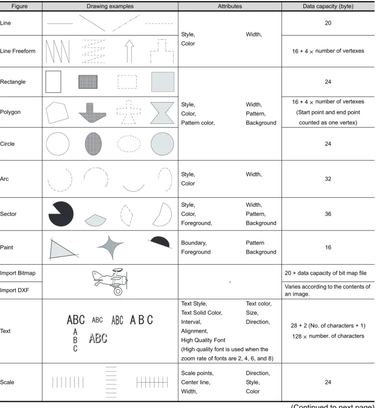
2.2 Figures and Data Capacity 2 - 9
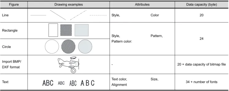
2.2.1 In the case of GOT-A900 series ... 2 - 9 2.2.2 In the case of GOT-F900 series ... 2 - 15
2.3 Specifications of Available Object Functions 2 - 18
2.3.1 In the case of GOT-A900 series ... 2 - 18 2.3.2 In the case of GOT-F900 series ... 2 - 30
2.4 Clock Function 2 - 36
2.4.1 Clock function for monitoring by GOT... 2 - 36 2.4.2 PLC CPU with clock function (GOT-A900 series only) ... 2 - 38
2.5 Overlap Setting 2 - 40
2.5.1 Overlap between figure and object ... 2 - 40 2.5.2 Overlap between objects ... 2 - 40
2.6 Supported Devices 2 - 42
2.6.1 GOT internal devices ... 2 - 42 2.6.2 Device range available for GOT-A900 series ... 2 - 49 2.6.3 Device range available for GOT-F900 series ... 2 - 64
2.7 Precautions for Object Setting 2 - 74
INTRODUCTION
Thank you for choosing Mitsubishi Graphic Operation Terminal (Mitsubishi GOT).
Read this manual and make sure you understand the functions and performance of the GOT thoroughly in advance to ensure correct use.
CONTENTS
SAFETY PRECAUTIONS ...A - 1 Cautions for using this software ...A - 2 REVISIONS...A - 4 INTRODUCTION...A - 6 CONTENTS ...A - 6 Function Quick Reference...A - 14 Manuals...A - 23 Abbreviations and Generic Terms...A - 24 How to Use This Manual ...A - 29
3.1 GOT/ PLC Type Setting 3 - 1 3.1.1 Settings... 3 - 1 3.1.2 Setting items... 3 - 2 3.1.3 Precautions... 3 - 3
3.2 Switching Screen Device Setting 3 - 5
3.2.1 Settings... 3 - 8 3.2.2 Setting items... 3 - 9 3.2.3 Precautions... 3 - 11
3.3 Switching Station No. Device Setting 3 - 12
3.3.1 Methods of switching station No... 3 - 12 3.3.2 Settings... 3 - 15 3.3.3 Setting items... 3 - 16 3.3.4 Precautions... 3 - 18
3.4 Password Setting 3 - 19
3.4.1 Settings... 3 - 20 3.4.2 Password setting items... 3 - 21 3.4.3 Precautions... 3 - 25
3.5 System Information Setting 3 - 26
3.5.1 Setting methods... 3 - 29 3.5.2 Setting items... 3 - 29 3.5.3 Application example ... 3 - 38 3.5.4 Precautions... 3 - 46
3.6 Print Format Setting 3 - 47
3.6.1 Settings... 3 - 47 3.6.2 Setting items... 3 - 48 3.6.3 Precautions... 3 - 49
4. PREPARATORY OPERATION FOR OBJECT SETTING 4 - 1 to 4 - 72
4.1 Comment Registration 4 - 1
4.1.1 Required knowledge for comment registration ... 4 - 1 4.1.2 Basic operation for comment registration ... 4 - 3 4.1.3 Registering a comment... 4 - 8 4.1.4 Copying or cutting a comment registered... 4 - 10 4.1.5 Deleting/clearing the text of a comment registered ... 4 - 13 4.1.6 Changing the registered comment's settings... 4 - 15 4.1.7 Saving/reading a comment as file ... 4 - 16 4.1.8 Editing the comment as text/csv file ... 4 - 19 4.1.9 Precautions for comment registration ... 4 - 23
4.2 Parts Registration 4 - 24
4.2.1 Required knowledge for parts registration ... 4 - 24 4.2.2 Basic operation for parts registration... 4 - 26 4.2.3 Registering parts ... 4 - 28 4.2.4 Copying the registered parts ... 4 - 31 4.2.5 Deleting the registered parts ... 4 - 32 4.2.6 Changing the registered parts settings... 4 - 33 4.2.7 Changing property of the registered parts ... 4 - 34
A - 8
4.2.8 Precautions... 4 - 35
4.3 Storing a BMP file part in the PC card 4 - 37
4.3.1 Before using the BMP image parts ... 4 - 39 4.3.2 Storing the BMP file parts into the PC card ... 4 - 40 4.3.3 Precautions... 4 - 41
4.4 Registering Gaiji 4 - 42
4.4.1 What are external characters... 4 - 42 4.4.2 Setting... 4 - 42 4.4.3 Setting items ... 4 - 42 4.4.4 Precautions... 4 - 44
4.5 Auxiliary Settings 4 - 45
4.5.1 Settings... 4 - 51 4.5.2 Setting items ... 4 - 52 4.5.3 Precautions... 4 - 59
4.6 Key Window 4 - 61
4.6.1 Key window type... 4 - 61 4.6.2 Keys on default key window and display items... 4 - 62 4.6.3 How to operate key window... 4 - 63 4.6.4 How to create user-created key window... 4 - 65 4.6.5 Precautions... 4 - 72
5. COMMON SETTINGS FOR OBJECTS 5 - 1 to 5 - 64
5.1 Device Setting 5 - 1
5.1.1 Device setting ... 5 - 1 5.1.2 Settings... 5 - 2 5.1.3 Setting items ... 5 - 3
5.2 Numeric Data that can be Handled with GOT 5 - 19
5.3 Object Arrangement and Display Image Setting 5 - 20
5.3.1 Object arrangement ... 5 - 20 5.3.2 Object shape setting ... 5 - 22 5.3.3 Object size change ... 5 - 25
5.4 State Setting 5 - 28
5.4.1 Display priority ... 5 - 29 5.4.2 Arrangement and settings... 5 - 29 5.4.3 Setting items ... 5 - 30 5.4.4 Example of state setting operation ... 5 - 33 5.4.5 Precautions... 5 - 34
5.5 Trigger Setting 5 - 35
5.5.1 Arrangement and settings... 5 - 41 5.5.2 Setting items ... 5 - 41 5.5.3 Precautions... 5 - 43
5.6 Data Operation Function 5 - 45
5.6.1 Arrangement and settings... 5 - 48 5.6.2 Setting items ... 5 - 49 5.6.3 Precautions... 5 - 51
5.7 Offset Function 5 - 52
5.7.1 Arrangement and settings... 5 - 54
5.7.3 Precautions... 5 - 54
5.8 Security Function 5 - 56
5.8.1 Security function setting ... 5 - 63 5.8.2 Precautions... 5 - 64
6. LAMP, SWITCH 6 - 1 to 6 - 83
6.1 Lamp Display 6 - 1
6.1.1 Arrangement and settings ... 6 - 2 6.1.2 Setting items of bit lamp ... 6 - 3 6.1.3 Setting items of word lamp (for GOT-A900 series only) ... 6 - 6 6.1.4 Setting items of bit lamp area (for GOT-F900 series only) ... 6 - 13 6.1.5 Setting items of screen lamp (for GOT-F900 series only) ... 6 - 13 6.1.6 Setting items of external lamp (for GOT-F900 series only) ... 6 - 14 6.1.7 Precautions... 6 - 14
6.2 Touch Switch 6 - 15
6.2.1 Arrangement and settings ... 6 - 18 6.2.2 Setting items of bit switch ... 6 - 19 6.2.3 Setting items of data set switch ... 6 - 36 6.2.4 Setting items of special function switch ... 6 - 41 6.2.5 Setting items of go to screen switch ... 6 - 49 6.2.6 Setting items of change station No. switch (specific for GOT-A900 series) ... 6 - 59 6.2.7 Setting items of key code switch ... 6 - 65 6.2.8 Setting items of data change switch (specific for GOT-F900 series)... 6 - 68 6.2.9 Setting items of recipe transfer switch (specific for GOT-F900 series)... 6 - 71 6.2.10 Setting items of multi action switch... 6 - 73 6.2.11 Keyboard function... 6 - 78 6.2.12 Precautions... 6 - 80
7. NUMERICAL/CHARACTER DISPLAY 7 - 1 to 7 - 83
7.1 Numerical Display/Numerical Input 7 - 1
7.1.1 Arrangement and settings ... 7 - 3 7.1.2 Setting items of numerical display ... 7 - 4 7.1.3 Setting items of numerical input ... 7 - 13 7.1.4 Precautions... 7 - 24
7.2 Data List 7 - 28
7.2.1 Required knowledge for data list setting... 7 - 29 7.2.2 Arrangement and settings ... 7 - 31 7.2.3 Setting items... 7 - 32 7.2.4 Precautions... 7 - 43
7.3 ASCII Display/Input 7 - 44
7.3.1 Before setting ASCII display/input ... 7 - 46 7.3.2 Arrangement and settings ... 7 - 47 7.3.3 Setting items... 7 - 48 7.3.4 Precautions... 7 - 55
7.4 Clock Display 7 - 57
7.4.1 Arrangement and Settings... 7 - 58 7.4.2 Setting items... 7 - 59
A - 10
7.4.3 Precautions... 7 - 62
7.5 Comment Display 7 - 63
7.5.1 Arrangement and settings... 7 - 64 7.5.2 Setting items of bit comment ... 7 - 65 7.5.3 Setting items of word comment ... 7 - 72 7.5.4 Precautions... 7 - 83
8. ALARM 8 - 1 to 8 - 71
8.1 User Alarm Display 8 - 1
8.1.1 Before setting user alarm... 8 - 2 8.1.2 Placement and settings ... 8 - 9 8.1.3 Setting items ... 8 - 10 8.1.4 Touch switch for displaying user alarm... 8 - 19 8.1.5 Precautions... 8 - 20
8.2 System Alarm Display 8 - 23
8.2.1 Before setting system alarm ... 8 - 24 8.2.2 Placement and settings ... 8 - 27 8.2.3 Setting items ... 8 - 28 8.2.4 Precaution... 8 - 30
8.3 Alarm History Display 8 - 31
8.3.1 Before setting alarm history display... 8 - 33 8.3.2 Placement and setting ... 8 - 39 8.3.3 Setting items ... 8 - 41 8.3.4 Description on touch switches for alarm history display ... 8 - 62 8.3.5 Precautions... 8 - 64
8.4 Floating Alarm 8 - 67
8.4.1 Settings... 8 - 68 8.4.2 Setting items of floating alarm ... 8 - 69 8.4.3 Precautions... 8 - 71
9. PARTS 9 - 1 to 9 - 62
9.1 Parts Display 9 - 1
9.1.1 Parts displaying method ... 9 - 3 9.1.2 Arrangement and settings... 9 - 7 9.1.3 Setting items of bit parts display ... 9 - 8 9.1.4 Setting items of word parts display ... 9 - 13 9.1.5 Setting items of fixed parts display ... 9 - 23 9.1.6 Precautions... 9 - 26
9.2 Parts Movement 9 - 28
9.2.1 Moving and displaying parts ... 9 - 29 9.2.2 Setting of parts move route (common setting for each screen) ... 9 - 37 9.2.3 Arrangement and setting ... 9 - 39 9.2.4 Setting items of bit parts movement ... 9 - 40 9.2.5 Setting items of word parts movement ... 9 - 46 9.2.6 Setting items of fixed parts movement... 9 - 57 9.2.7 Precautions... 9 - 62
10.1 Panelmeter 10 - 1 10.1.1 Required knowledge for panelmeter setting ... 10 - 1 10.1.2 Arrangement and settings ... 10 - 3 10.1.3 Setting items... 10 - 4 10.1.4 Precautions... 10 - 13
10.2 Level 10 - 14
10.2.1 Required knowledge for level setting... 10 - 15 10.2.2 Arrangement and settings ... 10 - 17 10.2.3 Setting items... 10 - 19 10.2.4 Precautions... 10 - 26
10.3 Trend Graph 10 - 28
10.3.1 Required knowledge for trend graph setting... 10 - 28 10.3.2 Arrangement and settings ... 10 - 31 10.3.3 Setting items... 10 - 32 10.3.4 Precautions... 10 - 43
10.4 Line Graph 10 - 44
10.4.1 Required knowledge for line graph setting ... 10 - 44 10.4.2 Arrangement and settings ... 10 - 46 10.4.3 Setting items... 10 - 47 10.4.4 Precautions... 10 - 58
10.5 Bar Graph 10 - 59
10.5.1 Required knowledge for bar graph setting... 10 - 59 10.5.2 Arrangement and settings ... 10 - 61 10.5.3 Setting items... 10 - 62 10.5.4 Precautions... 10 - 70
10.6 Statistics Graph 10 - 71
10.6.1 Required knowledge for statistics graph setting ... 10 - 72 10.6.2 Arrangement and settings ... 10 - 73 10.6.3 Setting items... 10 - 74 10.6.4 Precautions... 10 - 80
10.7 Scatter Graph 10 - 81
10.7.1 Required knowledge for scatter graph setting ... 10 - 82 10.7.2 Arrangement and settings ... 10 - 88 10.7.3 Setting items... 10 - 89 10.7.4 Precautions... 10 - 101
10.8 Sampling 10 - 102
10.8.1 Settings... 10 - 102 10.8.2 Setting items... 10 - 103 10.8.3 Precautions... 10 - 104
11. TRIGGER ACTIONS 11 - 1 to 11 - 28
11.1 Status Observation Function 11 - 1
11.1.1 Settings... 11 - 2 11.1.2 Setting items... 11 - 3 11.1.3 Precautions... 11 - 10
11.2 Recipe Function 11 - 12
A - 12
11.2.1 Settings... 11 - 13 11.2.2 Setting items ... 11 - 14 11.2.3 Precautions... 11 - 20
11.3 Time Action Function 11 - 22
11.3.1 Settings... 11 - 23 11.3.2 Setting items ... 11 - 24 11.3.3 Precautions... 11 - 27
12. EXTERNAL INPUT/OUTPUT 12 - 1 to 12 - 73
12.1 Report Function 12 - 1
12.1.1 Arrangement and settings... 12 - 3 12.1.2 Report screen creation (screen property) ... 12 - 5 12.1.3 Setting common to each report (report setting) ... 12 - 8 12.1.4 Print layout setting ... 12 - 13 12.1.5 Precautions... 12 - 23
12.2 Hard Copy 12 - 25
12.2.1 Settings... 12 - 26 12.2.2 Setting items ... 12 - 27 12.2.3 Precautions... 12 - 29
12.3 Operation Panel 12 - 31
12.3.1 Required knowledge for operation panel setting ... 12 - 32 12.3.2 Settings... 12 - 33 12.3.3 Setting items ... 12 - 34 12.3.4 Precautions... 12 - 38
12.4 Bar Code Function 12 - 39
12.4.1 Arrangement and settings... 12 - 39 12.4.2 Settings... 12 - 40 12.4.3 Setting items of bar code function ... 12 - 41 12.4.4 Precautions... 12 - 42
12.5 Sound 12 - 46
12.5.1 Settings... 12 - 46 12.5.2 Setting items ... 12 - 47 12.5.3 Precautions ... 12 - 48
12.6 Video 12 - 50
12.6.1 Settings... 12 - 63 12.6.2 Setting items of video ... 12 - 64 12.6.3 Precautions... 12 - 67
12.7 RGB 12 - 68
12.7.1 Settings... 12 - 71 12.7.2 Setting items of RGB ... 12 - 72 12.7.3 Precautions... 12 - 73
13. OTHERS 13 - 1 to 13 - 12
13.1 Set Overlay Screen Function 13 - 1
13.1.1 Arrangement and settings... 13 - 2 13.1.2 Check of the settings ... 13 - 4 13.1.3 Precautions... 13 - 5
13.2.1 Arrangement and settings ... 13 - 11 13.2.2 Setting items... 13 - 11 13.2.3 Precautions... 13 - 12
14. SCRIPT FUNCTION 14 - 1 to 14 - 56
14.1 Overview 14 - 1
14.1.1 Features ... 14 - 1 14.1.2 Precautions for Use ... 14 - 3
14.2 Specifications 14 - 6
14.2.1 Type... 14 - 6 14.2.2 Control structure ... 14 - 7 14.2.3 Applicable data and representation methods ... 14 - 11 14.2.4 Script execution ... 14 - 20
14.3 Settings and Procedure for Execution 14 - 23
14.4 GT Designer2 Settings 14 - 24
14.4.1 Settings... 14 - 24 14.4.2 Setting items... 14 - 25 14.4.3 Precautions... 14 - 41 14.4.4 Message displayed during syntax check ... 14 - 41
14.5 Program Examples 14 - 43
14.5.1 Touch switches with interlock function ... 14 - 43 14.5.2 Lamps which change the display attributes under multiple conditions ... 14 - 44 14.5.3 Password input screen with time limit function ... 14 - 46
14.6 Precautions for using BMOV 14 - 48
14.7 Troubleshooting 14 - 51
14.7.1 Simulation using general C language compiler or debugger... 14 - 51 14.7.2 Errors and corrective actions for script execution on GOT ... 14 - 54
APPENDICES App - 1 to App - 18
App.1 Object Display Speed (Reference Value) App - 1
App.2 Key Code List App - 3
App.3 Drawing Sheet App - 6
App.4 Printing Time of Hard Copy Function (Reference Value) App - 12
App.5 Synthesized Colors Available for XOR App - 13
App.6 Comparison between GT Designer terms and GT Designer2 terms App - 16
App.7 List of Functions Added by GT Designer2 Version Upgrade (For GOT900 Series) App - 17
INDEX Index - 1 to Index - 6
A - 14
Function Quick Reference
Edit Operation (GT Designer2 Version Operating Manual)
Image Function Page
Shows the preview of screen image of GOT. Page 4-43
Aligns objects or images Page 8-22
Sets same attributes to objects or images in the
same screen Page 9-1
Displays lines to align figures and objects when
arranging a placed figure or object. Page 8-25
Changes the color(s) of the objects and figures
arranged on plural screens at the same time Page 9-12
Changes the switch/lamp figures at the same
time Page 9-12
Changes the preset devices at the same time Page 9-12
Overlapping images or objects Page 9-16
Display the set device in list Page 9-17 Preview
Align
Property sheet
Guidelines
Replace colors
Base 3 Base 2
Base 1
Base 3 Base 2
Base 1
Replace shapes
Base 3 Base 2
Base 1
Base 3 Base 2
Base 1
Replace devices
M10 M11 M12 M100 M101 M102
Data View
Select
Base 3 Device list
Base 2
Base 1
D100 Numerical display D200 ASCII display
300 Panel meter display
Displays the direct input texts in a list. Page 9-19
Input characters or comments in other
language. Page 9-26
Imports BMP/DXF files Page 8-13
Utilizes other project data Page 9-35
Text list
Run Bit Switch
Word Lamp Base 2
Base 3
Base 1
Stop Error
Bit Switch
Multiple language input
English
Man. Auto
Chinese
Import BMP/DXF file
DXF file
BMP file Import
Import Project
Import
A - 16
Object Functions (GT Designer2 Version Reference Manual) 1 Lamp/Switch
2 Digit/font display
Image Function Page
Displays device value via lamp color
changing Page 6-1
Touch it to switch device ON/OFF Page 6-19
Touch it to change bit device value Page 6-36
Touch it to switch the screen to such as
Utility screen. Page 6-41
Touch it to switch between the base and
window screen Page 6-49
Touch it to switch the monitored PLC station
No. Page 6-59
Used as the key for inputting numerical
value/ASCII Page 6-65
Image Function Page
Displays device value in numerical value Page 7-1
Write value on device Page 7-1
Lamp display
RUN STOP
Red Blue
Bit switch
MO:ON OFF
Data set switch
D100:
200 350
Special function switch
Go to screen switch
Base 1 Base 2
Operation Stop
Change station No. switch
Change monitor destination
A A B C D E F G H
Key code switch
D100:334 D100 334
Numerical display
D100 45
D100:45 Numerical input
3 Alarm
4 Parts
Display multipledevice value in list Page 7-28
Displays device value in text Page 7-44
Inputs text code device Page 7-44
Displays hour/minutes, year/month/date Page 7-57
Displays command Page 7-63
Image Function Page
Displays message at alarm occurence Page 8-1
Displays alarm history Page 8-31
Displays alarm in floating Page 8-67
Image Function Page
Display entered device Page 9-1
Displays moving parts Page 9-28
D100 55 122 34
D100: 55 D101:122 D102: 34 Data list
D101 D102
ASCII display
ABCD D10:4241H(BA)
D11:4443H(DC)
A B C D D10:4241H(BA)
D11:4443H(DC) ASCII input
Clock display
15:27 02/03/18
Comment display
RUN STOP
Alarm list
02/04/18 13:25:40 RUN STOP
Alarm history display
13:25 RUN A STOP 13:05 Hight limit over 13:03 Motor trip Time message
Alarm flow display
Alarm occur Alarm
Parts display
Part1 Part2
Parts movement display
A - 18
5 Graph/Meter
Image Function Page
Displays device data on panel meter Page 10-1
Displays device data in proportional level Page 10-14
Displays device data in trend graph Page 10-28
Displays device data in line graph Page 10-44
Displays device data in bar graph Page 10-59
Displays device data in statistics graph Page 10-71
Displays device data in scatter grap Page 10-81
Collect the device value and edit collected
data on PC Page 10-102
Panel meter display
Level display
Trend graph display
Line graph display
Bar graph display
Statistics graph display
Circle graph Bar graph
Scatter graph display
Sampling
7 External input/output
Image Function Page
Monitors status of device and write value to device or operates GOT when condition meets
Page 11-1
Monitors status of device and write/read
device data when condition meets Page 11-12
Outputs the device writing and sound at
specified time. Page 11-22
Image Function Page
Collects numerical data when condition meets and prints the numerical data and corresponding code.
Page 12-1
Outputs the GOT monitor screen to printer or
PC card Page 12-25
Uses operation panel to execute device
writing Page 12-31
Writes data read by bar code reader to
device Page 12-39
Outputs sounds Page 12-46
Status observation function
Write D100: 0 150
Recipe functioin
Write /Read
D100:
D101:
D102:
150 300 208
Time action function
Report
Hardcopy
X0
Operation panel
1350
Bar code
Sound
A - 20
8 Others
9 Script function
10 Object setting
Displays video Page 12-50
Displays PC screens Page 12-68
Image Function Page
Set overlay screen from other screens Page 13-1
Changes device value via test window in
monitor screen Page 13-10
Image Function Page
Controls GOT display by scripts Page 14-1
Image Function Page
Operates device values by expression and
enables objects using the operated value Page 5-45
Accumulates the offset device value in
monitor device address and monitor. Page 5-52
Image Function Page
Video
RGB display
Menu
Menu
Menu
Set overlay screen
Base 3
Base 1
Base 2
Test
Script
if(([b:X1]==OFF)&&([b:X2]==OFF)&&([b:X3]==OFF)) {[w:D10]=1;}
if(([b:X1]==ON)&&([b:X2]==OFF)&&([b:X3]==OFF)) {[w:D10]=2;}
if(([b:X1]==OFF)&&([b:X2]==ON)&&([b:X3]==OFF)) {[w:D10]=3;}
if(([b:X1]==OFF)&&([b:X2]==OFF)&&([b:X3]==ON)) {[w:D10]=4;}
D100
D100 : 45
180
Data operation
180
200 10
Offset
Numerical value input: D100
Offset device: D200 Write to D110
Restricts the password users Page 5-56
*****
Security
A - 22
Data Transmission (GT Designer2 Version Operating Manual)
Print (GT Designer2 Version Operating Manual)
Image Function Page
Transimits monitor screen data from PC to
GOT Page 5-1
Transmits monitor screen data from GOT to
PC Page 5-20
Image Function Page
Prints the project information (screen image,
title list, etc.). Page 6-1
Download
Upload
Print screen
Manuals
The following table lists the manual relevant to this product.
You can order it as necessary.
Related Manuals
Manual Name Manual Number
(Type code) GT Designer2 Version2 Operating Manual (Startup • Introductory Manual)
Describes methods of installing GT Designer2 and introductory drawing methods (Sold separately) (Sold separately)
SH-080520ENG (1DM215)
GT Designer2 Version2 Operating Manual
Describes methods of operating GT Designer2 and transmitting data to GOT
(Sold separately)
SH-080521ENG (1DM216)
GOT-A900 Series Operating Manual
(GT Designer2 Version2 compatible Extended • Option Functions Manual)
Describes the following extended functions and optional functions applicable to GOT Extended and optional function of GOT are as follows:
• Utility • Ladder monitor • System monitor
• Special module monitor • Network monitor • List editing
• Module monitor • Servo amplifier monitor • CNC monitor
• Font change • System dialog language switching
(Sold separately)
SH-080523ENG (1DM218)
GOT-A900 Series User's Manual
(GT Designer2 Version2 compatible Connection System Manual)
Describes the system configuration of which connection method is compatible with GOT-A900 series as well as processing cables
(Sold separately)
SH-080524ENG (1DM219)
GOT-A900 Series Operating Manual
(GT Designer2 Version2 compatible Gateway Functions Manual)
Describes the gateway function specifications, system configuration and methods of setting GOT-A900 series
(Sold separately)
SH-080525ENG (1DM220)
A985GOT/A975GOT/A970GOT/A960GOT User's Manual
Provides performance specification, setting method, and communication board/communication module installation method of each GOT
(Sold separately)
SH-4005 (1DM099)
A950GOT/A951GOT/A953GOT/A956GOTUser's Manual
Provides performance specification, setting method, and communication board/communication module installation method of each GOT
(Sold separately)
SH-080018 (1DM103)
GOT-F900 Series HARDWARE Manual [CONNECTION]
Explains the specifications, system configuration and connection diagram of each connection form avail- able for the GOT-F900 series.
(Sold separately)
JY992D94801 (09R805)
GOT-F900 Series OPERATION Manual [GT Designer2 Version]
Explains the drawing specifications, utility function/HPP mode/special function unit monitoring function specifications, and dedicated monitor screen operation methods available for the GOT-F900 series.
(Sold separately)
JY997D09101 (09R813)
A - 24
Abbreviations and Generic Terms
Abbreviations and generic terms used in this manual are as follows:
GOT
Abbreviations and generic terms Description
GOT-A900 series
A985GOT-V A985GOT-TBA-V, A985GOT-TBD-V
A985GOT A985GOT-TBA, A985GOT-TBD, A985GOT-TBA-EU
A975GOT A975GOT-TBA-B, A975GOT-TBD-B, A975GOT-TBA,
A975GOT-TBD, A975GOT-TBA-EU
A970GOT
A970GOT-TBA-B, A970GOT-TBD-B, A970GOT-TBA,
A970GOT-TBD, A970GOT-SBA, A970GOT-SBD,
A970GOT-LBA, A970GOT-LBD, A970GOT-TBA-EU,
A970GOT-SBA-EU, A970GOT-LBA-EU
A97*GOT A975GOT, A970GOT
A960GOT A960GOT-EBA, A960GOT-EBD, A960GOT-EBA-EU
A956WGOT A956WGOT-TBD
A956GOT
A956GOT-TBD, A956GOT-SBD, A956GOT-LBD, A956GOT-TBD-M3, A956GOT-SBD-M3, A956GOT-LBD-M3 A956GOT-SBD-B, A956GOT-SBD-M3-B
A953GOT
A953GOT-TBD, A953GOT-SBD, A953GOT-LBD, A953GOT-TBD-M3, A953GOT-SBD-M3, A953GOT-LBD-M3 A953GOT-SBD-B, A953GOT-SBD-M3-B
A951GOT
A951GOT-TBD, A951GOT-SBD, A951GOT-LBD, A951GOT-TBD-M3, A951GOT-SBD-M3, A951GOT-LBD-M3 A951GOT-SBD-B, A951GOT-SBD-M3-B
A951GOT-Q
A951GOT-QTBD, A951GOT-QSBD, A951GOT-QLBD, A951GOT-QTBD-M3, A951GOT-QSBD-M3, A951GOT-QLBD-M3 A951GOT-QSBD-B, A951GOT-QSBD-M3-B
A950GOT
A950GOT-TBD, A950GOT-SBD, A950GOT-LBD, A950GOT-TBD-M3, A950GOT-SBD-M3, A950GOT-LBD-M3 A950GOT-SBD-B, A950GOT-SBD-M3-B
A95*handy GOT A950GOT-SBD-M3-H, A950GOT-LBD-M3-H, A953GOT-SBD-M3-H, A953GOT-LBD-M3-H
A95*GOT A956GOT, A953GOT, A951GOT, A951GOT-Q,
A950GOT
GOT-F900 series
F940GOT F940GOT-SWD, F940GOT-LWD, ET-940BH(-L),
ET-940PH(-L)
F930GOT-K F930GOT-BBD-K
F930GOT F930GOT-BWD, F933GOT-BWD
F920GOT-K F920GOT-BBD5-K, F920GOT-BBD-K
F940 handy GOT
F940GOT-SBD-H, F940GOT-LBD-H, F940GOT-SBD-RH, F940GOT-LBD-RH, F943GOT-SBD-H, F943GOT-LBD-H, F943GOT-SBD-RH, F943GOT-LBD-RH
F940WGOT F940WGOT-TWD
Option Module
Abbreviations and generic terms Description
Communication board
Bus connection board A9GT-QBUSS, A9GT-QBUS2S, A9GT-BUSS, A9GT-BUS2S,
A9GT-50WQBUSS, A9GT-50WBUSS Serial communication
board
A9GT-RS4, A9GT-RS2, A9GT-RS2T, A9GT-50WRS2, A9GT-50WRS4
Communication module
Bus connection module A9GT-QBUS2SU, A9GT-BUSSU, A9GT-BUS2SU, A7GT-BUSS, A7GT-BUS2S
Data link module A7GT-J71AP23, A7GT-J71AR23, A7GT-J71AT23B
Network module A9GT-QJ71LP23, A9GT-QJ71BR13, A7GT-J71LP23, A7GT-J71BR13 CC-Link communication
module A8GT-J61BT13, A8GT-J61BT15
Ethernet communication
module A9GT-J71E71-T
Abbreviations and generic terms Description
Option Module
External I/O module A9GT-70KBF, A8GT-50KBF Printer interface module A9GT-50PRF type
Memory card interface
module A1SD59J-MIF
Video/RGB mixed input
interface module A9GT-80V4R1 Video input interface
module A9GT-80V4
RGB input interface
module A9GT-80R1
A - 26 Option
Software
Abbreviations and generic terms Description
Option
Backlight A9GT-80LTT, A9GT-70LTTB, A9GT-70LTT, A9GT-70LTS,
A9GT-50LT, F9GT-40LTS, F9GT-30LTB
Debug stand A9GT-80STAND, A9GT-70STAND, A9GT-50WSTAND, A9GT-50STAND
Memory board
A9GT-FNB, A9GT-FNB1M, A9GT-FNB2M, A9GT-FNB4M,
A9GT-FNB8M, A9GT-QFNB, A9GT-QFNB4M, A9GT-QFNB8M, F9GT-40FMB, F9GT-40UMB
Ten-key panel A8GT-TK Bus connector
conversion box A7GT-CNB Bus distance connector
box A9GT-QCNB
Protective sheet A9GT-80PSC, A9GT-70PSC, A9GT-60PSC, A9GT-50WPSC,
A9GT-50PSC, F9WGT-40PSC, F9GT-40PSC, F9GT-30PSC
Attachment A77GT-96ATT, A85GT-95ATT, A87GT-96ATT, A87GT-97ATT
PC card (memory card) Flash PC card/Commercially available flash PC card/SRAM type PC card Flash PC card A9GTMEM-10MF, A9GTMEM-20MF, A9GTMEM-40MF Compact Flash PC card Commercially available flash PC card
Connector conversion
box Abbreviation of F9GT-HCNB
Abbreviations and generic terms Description
Software
GT Works2 Version SW D5C-GTWK2-E, SW D5C-GTWK2-EV GT Designer2 Version SW D5C-GTD2-E, SW D5C-GTD2-EV
GT Designer2 Abbreviation of GOT900 series graphic software-GT Designer2
GT Simulator2 Abbreviation of screen simulator GT Simulator2 for GOT1000/GOT900 series GT SoftGOT2 Abbreviation of monitoring software-GT SoftGOT2
GT Converter Abbreviation of GOT900 series data conversion software-GT Converter
GX Developer Abbreviation of SW D5C-GPPW(-V)/SW D5F-GPPW(-V) type software package
GX Simulator Abbreviation of SW D5C-LLT(-V) type download test tool function software package (SW5D5C-LLT(-V) or later)
DU/WIN Abbreviation of FX-PCS-DU/WIN
CPU
Inverter
Abbreviations and generic terms Description
License key A9GTSOFT-LKEY-P (for DOS/VPC)
License key FD SW5D5F-SGLKEY-J (for PC CPU module)
Abbreviations and generic terms Description
QCPU
QCPU (Q Mode)
Q00JCPU, Q00CPU, Q01CPU, Q02CPU,
Q02HCPU, Q06HCPU, Q12HCPU, Q25HCPU,
Q12PHCPU, Q25PHCPU
QCPU (A Mode) Q02CPU-A, Q02HCPU-A, Q06HCPU-A
Remote I/O station Network module for MELSECNET/H network system remote I/O station (QJ72LP25-25, QJ72LP25G, QJ72BR15)
QnACPU QnACPU type Q2ACPU, Q2ACPU-S1, Q2AHCPU, Q2AHCPU-S1,
Q3ACPU, Q4ACPU, Q4ARCPU
QnASCPU type Q2ASCPU, Q2ASCPU-S1, Q2ASHCPU, Q2ASHCPU-S1
ACPU
AnUCPU A2UCPU, A2UCPU-S1, A3UCPU, A4UCPU
AnACPU A2ACPU, A2ACPU-S1, A3ACPU
AnNCPU A1NCPU, A2NCPU, A2NCPU-S1, A3NCPU
AnCPU type AnUCPU, AnACPU, AnNCPU
AnUS (H) CPU A2USCPU, A2USCPU-S1, A2USHCPU-S1, A3USCPU
AnS (H) CPU A1SCPU, A1SCPUC24-R2, A2SCPU, A2SCPU-S1,
A1SHCPU, A2SHCPU, A2SHCPU-S1
A1SJ (H) CPU A1SJCPU, A1SJCPU-S3, A1SJHCPU
AnSCPU type AnUS(H)CPU, AnS(H)CPU, A1SJ(H)CPU
A1FXCPU A1FXCPU
A0J2HCPU, A2CCPU, A2CCPUC24, A2CJCPU
FXCPU
FX0 series, FX0N series, FX0S series, FX1 series, FX1N series, FX1NC series, FX1S series, FX2 series, FX2C series, FX2N series, FX2NC series,
FX(2N)-10GM/20GM series FX3UC series,
Motion controller CPU
Motion controller CPU
(Q series) Q172CPU, Q173CPU
Motion controller CPU (A series)
A273UCPU, A273UHCPU, A273UHCPU-S3,
A373CPU, A373UCPU, A373UCPU-S3,
A171SCPU, A171SCPU-S3, A171SCPU-S3N,
A171SHCPU, A171SHCPUN, A172SHCPU,
A172SHCPUN, A173UHCPU, A173UHCPU-S1
FA controller LM610, LM7600, LM8000
MELDAS C6/C64 FCA C6, FCA C64
Abbreviations and generic terms Description
FREQROL series A500 series, E500 series, F500 series
A - 28 Other PLC
Abbreviations and generic terms Description
Omron PLC
C200HS, C200H, C200H series (C200HX, C200HG,
C200HE), CQM1, C1000H, C2000H,
CV500, CV1000, CV2000,
CVM1-CPU01, CVM1-CPU11, CVM1-CPU21, CS1,
CS1D, CJ1H, CJ1G, CJ1M,
CPM1, CPM1A, CPM2A, CPM2C,
CQM1H
Yaskawa PLC
GL60S, GL60H, GL70H, GL120,
GL130, CP-9200SH, CP-9300MS, MP-920,
MP-930, MP-940, MP-9200(H), PROGIC-8
Allen- Bradley PLC
SLC500 series SLC500-20, SLC500-30, SLC500-40, SLC5/01,
SLC5/02, SLC5/03, SLC5/04, SLC5/05
MicroLogix1000 series
1761-L10BWA, 1761-L10BWB, 1761-L16AWA,
1761-L16BWA, 1761-L16BWB, 1761-L16BBB,
1761-L32AWA, 1761-L32BWA, 1761-L32BWB,
1761-L32BBB, 1761-L32AAA, 1761-L20AWA-5A,
1761-L20BWA-5A, 1761-L20BWB-5A MicroLogix1500 series 1764-LSP
Sharp PLC
JW-21CU, JW-22CU, JW-31CUH, JW-32CUH,
JW-33CUH, JW-50CUH, JW-70CUH, JW-100CU,
JW-100CUH, Z-512J
Toshiba PLC PROSEC T series T3, T3H, T2E, T2N
PROSEC V series Model3000, S2T
SIEMENS PLC SIMATIC S7-200 series, SIMATIC S7-300series,
SIMATIC S7-400 series
HITACHI PLC (HIDEC H series)
Large-sized H series
H-302(CPU2-03H), H-702(CPU2-07H), H-1002(CPU2-10H), H-2002(CPU2-20H), H-4010(CPU3-40H), H-300(CPU-03Ha), H-700(CPU-07Ha), H-2000(CPU-20Ha)
H-200 252 series
H-200(CPU-02H,CPE-02H), H-250(CPU21-02H),
H-252(CPU22-02H), H-252B(CPU22-02HB), H-252C(CPU22-02HC, CPE22-02HC)
H series board type
H-20DR, H-28DR, H-40DR, H-64DR,
H-20DT, H-28DT, H-40DT, H-64DT,
HL-40DR, HL-64DR
EH-150 series EH-CPU104, EH-CPU208, EH-CPU308, EH-CPU316
Matsushita Electric Works PLC
FP0-C16CT, FP0-C32CT, FP1-C24C, FP1-C40C,
FP2, FP2SH, FP2-CCU, FP3,
FP5, FP10 (S), FP10SH,
FP-M(C20TC), FP-M (C32TC)
Following symbols are used in this manual
* The above is user for explanation only and differs from the actual page.
Shows the items including detailed explanation (manual and the chapter, section, item).
Shows functions applicable to GOT-A900 series (GOT-A900) GOT-F900 series (GOT-F900).
" ", Applicable
" ", N / A
Shows functions applicable to GOT-A900 series (A) GOT-F900 series (F).
" ", Applicable
" ", N / A
Refers to information required for operation.
Refers to information useful for operation.
Refers to supplementary explanations.
Brackets used for the menu and items differ.
[ ] : Refers to menu in menu bar.
: Refers to dialog box item or GOT utility menu.
: Refers to dialog box buttons or PC keyboard.
Indicates the operation steps.
Remark
1 - 1 1.1 Overview
1. OVERVIEW
1.1 Overview
This manual explains the GT Designer2 common setting, object function specifications, object setting/
arrangement.
When applying any of the program examples introduced in this manual to the actual system, verify the appli- cability and confirm that no problems will occur in the system control.
1 GT Designer2-relevant manuals
The following manuals are relevant to the GT Designer2.
Refer to the corresponding manual according to needs.
Startup and Introduction
Describes the installation methods of the product, and explains the series of operations from creating simple screens to using them on GOT with example.
Reference manual
Provides specifications of object/figure/screen and setting methods of object Operating manual
Describes GT Designer2 screen configuration, screen customizing methods and the series of operations from object creation to data transfer.
Purpose Introductory ManualStartup Reference Manual Operating Manual
Installing product on PC
Creating projects
Creating screens
Drawing figures
Making common setting
Object arrangement/setting
Transferring data to GOT
Detailed
Overview
Detailed
Overview
Detailed
Overview
Detailed
Overview
Detailed
Overview
Detailed
Overview
Detailed
OVERVIEW
2
SPECIFICATIONS
3
COMMON SETTING
4
PREPARATORY OPERATION FOR OBJECT SETTING
5
COMMON SETTINGS FOR OBJECTS
6
LAMP, SWITCH
7
NUMERICAL/ CHARACTER DISPLAY
8
M
MEMO
2 - 1 2.1 Type/Number of Creatable Screens
2. SPECIFICATIONS
2.1 Type/Number of Creatable Screens
Type and number of creatable screens differ in GOT-A900 series and GOT-F900 series.
GOT-A900 series••• Base screen, window screen (overlap window, superimpose window, key window), and report screen.
GOT-F900 series••• Base screen, key window screen (the displaying method is overlap window).
348 A1254 B
348 B A1254
Pro.vol.
Pro.vol.
Pro.vol.
Vol.
10 20 50 60
Vol.
30 40 70 80
90100 105
115
Line Line
Base screen
The basic screen for screen display on GOT.
Window screen
A screen displayed over the base screen.
The created window screen can be displayed using either of the following methods.
L1 L2 L1 L2 L1 L2
L3 L4 L3 L4 L3 L4
02/11/18 16:
53:24 The production volum
e table Line
Vol.Line Vol.
Pro. vol.
Pro. vol.
Pro. vol. L1 L2 L3 L4 L3 L4 L3 L4 L1 L2 L1 L2
2010 6050 10090 10580704030
115
Production status screen 1
Production status screen 1
A pop-up window that appears over the base screen.
This type of window can be moved and closed manually.
Overlap window
A window composited on the base screen.
If superimposed window is switched, the
corresponding part of the base screen will be changed.
Superimposed window
Key window
A pop-up window displayed over the base screen when inputting (e.g. Numerical input). There are two types of key window: default key window and user-created key window.
A screen for data output and format creation using report function.
Report screen
02/11/18 16:53:24 The production volume table
Up to two windows can be displayed simultaneously.
( Section 2.1.1 Base screen specifications)
( Section 2.1.2 Window screen specifications)
( Section 12.1 Report Function)
OVERVIEW
2
SPECIFICATIONS
3
COMMON SETTING
4
PREPARATORY OPERATION FOR OBJECT SETTING
5
COMMON SETTINGS FOR OBJECTS
6
LAMP, SWITCH
7
NUMERICAL/ CHARACTER DISPLAY
8
M
2.1.1 Base screen specifications
The following table describes the base screen specifications.
2.1.2 Window screen specifications
The following table describes the window screen specifications.
*1 The values in " " (quotation marks) in the above table indicates the screen sizes when a close key and a movement bar are displayed on the overlap window.
For F94WGOT and F94*GOT, the close key and movement bar are additionally displayed on GOT side. (See below)
The close key and movement bar are not displayed on F93*GOT(-K).
*2 Create the screen of 638 322 dots or less for the usage of user-created key window.
If the screen of more than 638 322 dots is created, the user-created key window may not be displayed.
GOT type Screen size
(W H dots) Number of screens can be set Number of screens can be registered
GT SoftGOT 1280 1024, 1024 768
4096 1 to 32767
A985GOT/GT SoftGOT 800 600
A97*GOT/GT SoftGOT 640 480
A960GOT 640 400
A956WGOT 480 234
A95*GOT 320 240
F940WGOT 480 234
500 1 to 500
F94*GOT, CF94* handy GOT 320 240
F93*GOT(-K) 240 80
F920GOT-K 128 64
GOT type
Screen size (W H dots)
Number of screens can be
set
Number of screens can be registered
Initial value (W H dots) Maximum*1 Minimum
GT SoftGOT 800 480
"798 463"
94 81
1024 1 to 32767
318 176 A985GOT/GT SoftGOT
A97*GOT/GT SoftGOT 640 400
"638 383"*2 A960GOT
A956WGOT 480 234
"478 217"
190 126
A95*GOT 320 240
"318 223"
F940WGOT "480 214"
3 1 to 500
182 120
F94*GOT, F94* handy GOT "318 220" 182 120
F93*GOT(-K) "240 80" 16 20 182 80
F920GOT-K - - - - -
1 dot is used.
(For GOT-A900 series only) GOT-A900 series: 17 dots are used.
Close key and move bar provided Close key and move bar not provided
GOT-F900 series: 20 dots are used.
2 - 3 2.1 Type/Number of Creatable Screens 2.1.2 Window screen specifications
1 Methods of displaying window screen
(1) Methods of displaying window screens and superimpose screens
The created window screens will be displayed when the corresponding window screen No. is stored in the screen switching device for the window screen (overlap window, superimposed window).
Example: Relation between created window screen and device for switching window screen.
Screen switching device for overlap window 1 : D100 Screen switching device for superimposed window : D200
When erasing a window screen, store 0 to the device for screen switching. An overlap window can be erased by touching the close key, if it is displayed there.(0 will be stored to the device for screen switching.)
Section 3.2 Switching Screen Device Setting
(2) Methods of displaying key window
A key window is displayed by touching the numerical/ASCII input function objects.
Section 4.6 Key Window
B348 A 1254
348 B A 1254
348 B A1254
D100 0 1
D200 0 2
Created w indow screen Display w indow screen
1 as an overlap w indow . Window screen 1 Window screen 2
As 1 has been stored in the device f or superimpose w indow sw itching, the w indow screen 1 is displayed as an overlap w indow .
Display w indow screen 2 as a superimpose w indow
As 2 has been stored in the device f or sw itching superimpose w indow , the w indow screen 2 is displayed as a superimpose w indow .
Production status window 1
Production status window 1
Production status window 1
OVERVIEW
2
SPECIFICATIONS
3
COMMON SETTING
4
PREPARATORY OPERATION FOR OBJECT SETTING
5
COMMON SETTINGS FOR OBJECTS
6
LAMP, SWITCH
7
NUMERICAL/ CHARACTER DISPLAY
8
M
2 Display position of window screen
Set the display position using GT Designer2.
A window screen is displayed in the center of a base screen if its display position has not been set.
1 Select [Object] [Window Position] [Overlap Window 1]/[Overlap Window 2]/[Superimposed window]/[Key Window] from the menu.
2 Click the display position of each window.
(Specify multiples of 16 for the X and Y coordinates of the overlap window. If a non-multiple of 16 is specified for the coordinate, the overlap window is placed on the coordinate of the rounded down number when the remainder is 7 or less, or on the coordinate of the rounded up number when the remainder is 8 or more.)
Display position of overlap window
The display position of an overlap window can be controlled using device.
Section 3.2 Switching Screen Device Setting
When a window screen has been set to be out of the base screen
The window screen size will not be checked when setting its display position.Make sure to set the display position of a window screen while considering its screen size.
Window screen Set the position to the upper lef t of the screen.
Overlap window Base screen
When the window screen is out of the base screen, GOT will automatically move the window screen to inside of the base screen.
Window screen
The part outside the base screen will not be displayed.
The object will not be displayed.
Superimpose window
Base screen
Operation switch Opera
Window screen