Experimental Full Field Investigations of Resonant
Vibrations for Piezoceramic Plates by an Optical
Interferornetry Method
by Chien-Ching Ma and Chi-Hung Huang
ABSTRACT--The experimental measurement of resonantfrequencies for piezoelectric material is generally performed by impedance analysis. In this paper we employ an opti- cal interferometry method, called amplitude-fluctuation elec- tronic speckle pattern interferometry (AF-ESPI), to investi- gate the vibration characteristics of piezoceramic plates. This method demonstrates its advantages of combining noise re- duction, like the subtraction method, and high fringe sensi- tivity, like the time-averaged method. As compared with the film recording and optical reconstruction procedures used for holographic interferometry, the interferometric fringes of AF- ESPI are produced instantly by a video recording system. Based on the fact that clear fringe patterns measured by the AF-ESPI method will be shown only at resonant frequen- cies, both the resonant frequencies and corresponding mode shapes are obtained experimentally at the same time. Excel- lent quality for the interferometric fringe patterns of the mode shapes is demonstrated. We find from experimental results that the out-of-plane vibration modes (type A) with lower reso- nant frequencies cannot be measured by impedance analysis and only the in-plane vibration modes (type B) will be shown. However, both the out-of-plane (bending) and in-plane (ex- tension) vibration modes of piezoceramic plates are obtained by the AF-ESPI method. Finally, numerical finite element cal- culations are also performed, and the results are compared with the experimental measurements. Excellent agreement for the resonant frequencies and mode shapes are obtained from both results.
KEY WORDS--AFESPI, resonant frequency, mode shape, partially-electrode, piezoceramic plate
Introduction
Electronic speckle pattern interferometry (ESPI), which was first proposed by Butters and Leendertz ~ to investigate the out-of-plane vibration of disks, is a full-field, noncontact, and real-time optical metrology to measure the deformation of structures subjected to various kinds of loadings. This method has opened a new field of activity and been used in many industrial applications involving the investigation
Chien-Ching Ma is a Professol; Department of Mechanical Engineering, National Taiwan University, Taipei, Taiwan 106, Republic of China. Chi- Hung Huang is an Associate Professor, Department of Mechanical Engineer- ing, Ching Yun Institute of Technology, Chung-Li, Taiwan, 320, Republic of China.
Original manuscript submitted: July 18, 2000. Final manuscript received: January 8, 2002.
of static and dynamic deformation and condition monitoring of machinery. Although different methods of holographic interferometry 2 have been developed for vibration analysis, the slow and cumbersome process of film development lim- its the application of holographic vibration analysis in in- dustry. ESPI was developed by combining the techniques of holographic and speckle interferometry, employing an image hologram configuration and the method of double-exposure holography. Wang et al. 3 proposed the amplitude-fluctuation ESP! method for out-of-plane vibration measurement to in- crease the visibility of the fringe pattern and to reduce en- vironmental noise simultaneously. In the AF-ESPI method, the reference frame is recorded in a vibrating state and is subtracted from the incoming frames.
Piezoelectric transducers are widely used in electrome- chanical sensors, actuators, and non-destructive testing de- vices, as well as in electro-optic modulators, etc. Show 4 used an optical interference technique in which a stroboscop- ically illuminated multiple beam is applied to measure the surface motion of thick barium titanate disks. Holland 5 used the Rayleigh-Ritz method to study the extensional modes of rectangular piezoelectric plates and classified them into four distinct symmetry types. Chang 6 employed dual-beam speckle interferometry to measure the in-plane vibration am- plitude on the PZT surface. Brissaud et al. 7 proposed a two- dimensional model to determine the for shear displacement and electrical impedance for the shear modes of a piezoce- ramic plate. The simulated admittance curve for the funda- mental natural frequency was presented and compared with the experimental result. Bisegna and Maceri 8 derived the bending and stretching behavior of a piezoceramic plate from the three-dimensional theory of piezoelectricity, which was based on the initial function method. Ma and Huang 9' 10 used the AF-ESPI method to investigate the three-dimensional vi- bration of piezoelectric rectangular parallelepipeds and cylin- ders, and both resonant frequencies and mode shapes were presented.
The study of the vibration behavior of piezoelectric mate- rials is a problem of great practical interest. However, there are very few experimental results, especially for the full field measurement of mode shapes, available in the literature. In this paper, both an optical method based on the amplitude- fluctuation ESPI (AF-ESPI) and impedance analysis are em- ployed to study the experimental vibration characteristics of piezoceramic plates. The advantage of using the AF-ESPI method is that both resonant frequencies and the correspond- ing mode shapes can be obtained simultaneously from the
experimental investigation. The fringe patterns shown in the experimental results correspond to the vibrating mode shapes. According to the experimental results obtained in this study, the vibration modes of piezoceramic plates can be classified into two types, type A (out-of-plane) and type B (in-plane) modes. It is interesting to note that type A modes with lower resonant frequencies cannot be measured by impedance anal- ysis and the vibration mode shapes are similar to those of isotropic plates. To validate the conclusion, investigation of a piezoelectric plate with partial electrodes is also per- formed. In addition to the AF-ESP! experimental technique, numerical computations based on a finite element package are presented and good agreement for resonant frequencies and mode shapes are found.
The Theory of the AF-ESPI Method
The basic theory for out-of-plane vibrating measurement by ESPI is briefly discussed first. If the image is taken after the specimen vibrates periodically, the light intensity detected by a charge-coupled device (CCD) camera is indicated as I1. The AF-ESPI method is employed in this study by taking two images while the specimen vibrates and assuming that the vibration amplitude of the second image has changed from A to A + 2xA due to the instability of apparatus. The light intensity of the second image is indicated as/2. When these two images (I1 and/2) are subtracted and rectified by the image processing system, the resulting image intensity can be expressed as
I = /2 -- [1 -- - - ~ (cos dp)['2(AA)2Jo(PA) , (1) 2
where IA is the object light intensity, IB is the reference light intensity, ~ is the phase difference between object and reference light, J0 is a zeroth-order Bessel function of the first kind, and
21it
F = 7 ( 1 +cosO), (2)
in which k is the wavelength of the laser and 0 is the angle between object light and observation direction.
Similar to the out-of-plane vibration case, the first and second image intensities for in-plane vibration are denoted as I1 and I2, respectively. When these two images (Ii and/2) are subtracted and rectified by the image processing system, the image intensity is
I -= 12 -- I1 -- ~ / I A I B ( c o s ~ ) F ' 2 ( A A ' ) 2 J o ( [ " A ') (3) 2
where IA and IB are the object light intensities, A I is the amplitude of in-plane vibration, and
F' = ~ (2 sin 0l), (4)
in which 0' is half of the angle between two illumination lights.
From eq (1) and eq (3), it is indicated that both the out-of- plane and in-plane vibration fringe patterns obtained by the AF-ESPI method are dominated by the zeroth-order Bessel function J0. A detailed discussion of the AF-ESPI method
was provided by Ma and Huang. 9 Combining the out-of-plane and in-plane optical setups by the AF-ESPI method, we can construct complete vibration characteristics of the piezoelec- tric plate, including resonant frequencies and mode shapes at the same time. This is different from impedance analy- sis, which has been used widely in determining the resonant frequency for piezoelectric materials.
Experimental and Numerical Results
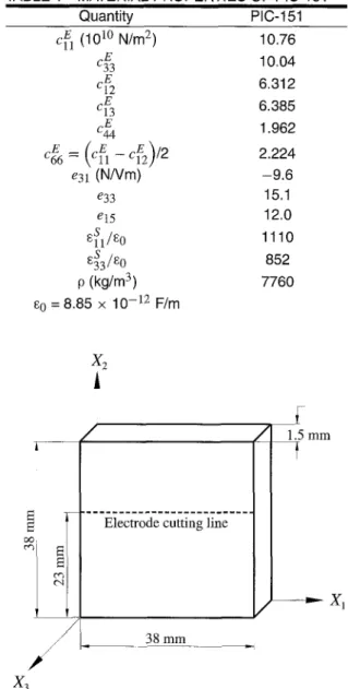
A piezoelectric plate made of Pb(Zr.Ti)O3 ceramic is se- lected for experimental investigations and the modal number is PIC-151 (Germany Physik Instrumente Company). The polarized piezoelectric ceramic has the same symmetry as a hexagonal crystal in class C6v = 6 ram, which can be mod- eled as a transversely isotropic material. The elastic, piezo- electric, dielectric constants and geometric dimensions of the specimens are shown in Table 1 and Fig. 1, respectively. The polarization axis is in the x3 direction and two opposite faces (Xl-X2 plane) of the specimen are completely coated with silver electrodes.
TABLE 1--MATERIAL PROPERTIES OF PIC-151
Quantity PIC-151 c(] (10 l~ N/m 2) 10.76 c3E3 10.04 c~: 2 6.312 c~3 6.385 c4~ 1.962 cff6 = (Cfl -- Cf2)/2 2.224 e31 (N/Vm) - 9 . 6 e33 15.1 e15 12.0 ss t/So 1110 s3s3/s0 852 p (kg/m 3) 7760 so = 8.85 x 10 -12 F/m
1
,
_ _ _ /
38 mm JFig. 1--Geometric dimensions of the piezoceramic plate
The schematic layout of self-arranged time-averaged AF- ESPI optical systems, as shown in Figs. 2 and 3, are used to perform the out-of-plane and in-plane experimental mea- surements for resonant frequencies and corresponding mode shapes. A H e - N e laser with 30 mW and wavelength k = 632.8 nm is used as the coherent light source. We use a CCD camera (Pulnix Company) and a P360F (Dipix Technologies, Inc.) frame grabber with a digital signal processor onboard to record and process the images. As shown in Fig. 2 for the out-of-plane measurement, the laser beam is divided into two parts, the object and reference beams, by a beamsplitter. The object beam travels to the specimen and then reflects to the CCD camera. The reference beam is directed to the CCD camera via a mirror and a reference plate. For the in-plane measurement system shown in Fig. 3, two laser beams with the same optical path and light intensity are symmetrically in- cident to the specimen, and then reflect to the CCD camera. The CCD camera converts the intensity distribution of the interference pattern of the object into a corresponding video signal at 30 frames per second. The signal is electronically processed and finally converted into an image on the video monitor. The interpretation of the fringe image is similar to reading of a contour map, To achieve the sinusoidal output, a function generator HP33120A (Hewlett Packard) connected to a 4005 power amplifier (NF Electronic Instruments) is used.
The experimental procedure of the AF-ESPI technique is performed as follows. First, a reference image is taken af- ter the piezoceramic plate vibrates, then the second image is taken, and the reference image is subtracted by the im- age processing system. If the vibrating frequency is not the natural frequency, only random distributed speckles are dis- played and no fringe patterns will be shown. However, if the vibrating frequency is in the neighborhood of the reso- nant frequency, stationary distinct fringe patterns will be ob- served. Then the function generator is carefully and slowly turned; the number of fringes will increase and fringe pattern will become clearer as the resonant frequency is approached. From the aforementioned experimental procedure, the reso- nant frequencies and the correspondent mode shapes can be determined at the same time.
According to the experimental results from using the AF- ESPI optical system, we find that the natural frequencies and corresponding mode shapes of the piezoceramic plate can be classified into two types, named type A and B modes in this paper. Comparing with type B modes, the natural frequencies of type A modes are much lower and the mode shapes can be obtained only by the out-of-plane measurement. Hence we can conclude that the type A modes are the out-of-plane vi- bration modes and the type B modes are the in-plane modes. In addition to the experimental measurement, numerical cal- culation is also investigated by the commercially available software ABAQUS 11 finite element package in which a 20- node three-dimensional brick element (C3D20E) is selected to analyze the problem. Both the experimental measurements obtained by impedance analysis and the numerical calcula- tion will be used in the comparison with the result measured by using the AF-ESPI method. Figs. 4 and 5 show the exper- imental and numerical results for the first five vibration mode shapes of type A and type B modes, respectively. We indicate the phase of displacement in the finite element results as solid or dashed lines; the solid lines are in the opposite direction to the dashed lines. The transition from solid lines to dashed
spatial filter Ke-Ne Laser beamsplitter specimen ~ ~ . or
- . i > < . . /
',
r e f e r e n c e i p l a t e t . . . . i i i i i iFig. 2--Schematic diagram of the AF-ESPI setup for out-of- plane measurement m i r r o r s p a t i a l f i l t e r " C C D I I I I m i r r o r I I I I I I I
Fig. 3--Schematic diagram of the AF-ESPI setup for in-plane measurement
lines corresponds to a zero displacement line, or a nodal line. The zeroth-order fringe, which is the brightest fringe in the experimental results, represents the nodal lines of the vibrat- ing piezoceramic plate at resonant frequencies. The rest of the fringes are contours of constant amplitudes of displace- ment, which can be quantitatively calculated by J~(FA) = 0 (or J~(FrA ') = 0) according to eq (1) (or eq (3)) for out-of- plane (or in-plane) measurement. Considering the sensibility of the experim~tal measurement, we choose 0 = 10 ~ and 0' = 60 ~ for the experimental setup. The mode shapes ob- tained by experimental results can be checked by the nodal lines and fringe patterns with the numerical finite element calculations, and excellent agreement is found.
Because the electrical impedance of the piezoceramic ma- terial drops to a local minimum when it vibrates at a resonant frequency, the resonant frequency can also be determined by impedance analysis. Here it is carried out by using an HP4194A impedance/gain-phase analyzer (Hewlett Packard) and the impedance curve for the piezoceramic plate measured from HP4194A is shown in Fig. 6. Unexpectedly we find that
mode out-of-plane( x3 ) FEM result mode 1 in-plane( xl ) FEM result
mode 2 out-of-plane( x3 ) FEM result mode 2 in-plane( x~ ) FEM result
mode 3 out-of-plane( x3 ) FEM result mode 3 in-plane( xl ) FEM result
mode 4 out-of-plane( x3 ) FEM result mode 4 in-plane( X I ) FEM result
mode 5 out-of-plane( x3 ) FEM result mode 5 in-plane( xl ) FEM result
Fig. 4--Mode shapes of type A obtained by AF-ESPI and FEM
(full electrodes) Fig. 5--Mode shapes of type B obtained by AF-ESPI and FEM (full electrodes)
only the resonant frequencies of the type B modes are indi- cated in Fig. 6, i.e., those of the type A modes cannot be obtained by impedance analysis. This phenomenon can be explained by the characteristics of piezoelectricity. When the piezoelectric plate vibrates at a resonant frequency, the charge will be induced on the electrode surfaces owing to the vibration deformation (the direct piezoelectric effect) and the impedance will drop to a local minimum value. This is why we can measure the resonant frequencies of piezoceramic plates by using the impedance analyzer. If the summation of the induced charge distributed over the electrode surfaces is zero, we will not be able to find a large variation of impedance
at the resonant frequency. Type A modes are just the situation mentioned above and we cannot obtain the resonant frequen- cies from the impedance curve shown in Fig. 6. Table 2 shows the first five resonant frequencies of the piezoceramic plate obtained by using AF-ESPI, impedance analysis, and the FEM method. The discrepancy of resonant frequencies between AF-ESPI and impedance analysis for type B modes is smaller than that between AF-ESPI and FEM. However, the difference between the experimental data and FEM may be a result of the measurement of the material properties and a defect of the piezoelectric material, which is generated by the manufacturing process.
TABLE 2--RESULTS OF RESONANT FREQUENCIES OBTAINED FROM AF-ESPI, IMPEDANCE ANALY- SIS AND FEN FOR THE PIEZOCERAMIC PLATE/FULL ELECTRODES)
Type A
AF-ESPI Impedance Analysis FEM
Mode (Hz) (Hz) (Hz) 1 1850 - - 1829 2 2820 - - 2763 3_ 4200 - - 4286 4 5000 - - 4938 5 9210 - - 9210 Type B
AF-ESPI Impedance Analysis FEM
Mode (Hz) (Hz) (Hz) 1 43800 43755 42653 2 62600 62753 60772 3 118600 118625 115535 4 122300 122375 119276 5 136700 136625 134083 ~J . \ 1 6 5 t 6 5 0
'-....
\
43;55 62753 75k Frequency (Hz)! 1 1
i Square Plate "~ Length = Width = 38 mm Thickness = 1.5 mm j ~ \ 625 18625 122375 150k Fig. 6--Impedance variation curve of the piezoceramic plate (full electrodes)mode 1 in-plane( xl ) in-plane( x2 )
FEM result FEM result
mode 2 in-plane( xj ) in-plane( x~ )
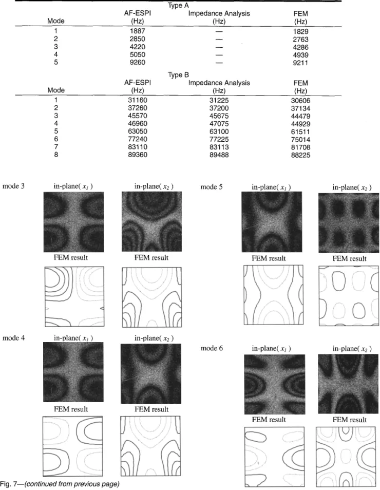
From observing the mode shapes of type A, we find that the vibration characteristics are similar to that of the out-of- plane vibration for an isotropic plate. Next, we slit the silver electrode of one surface of the piezoceramic plate to form the partial electrodes shown in Fig. 1. After performing the experimental procedure and numerical calculation as men- tioned above, we obtain results for the resonant frequencies and mode shapes for type A modes that are almost the same as those for the full-electrode specimen. Table 3 shows the res- onant frequencies of the partial-electrode specimen obtained by AF-ESPI, impedance analysis, and FEM methods. Since the type A mode shapes for the partial-electrode specimen are the same as that for the full-electrode case, only type B mode shapes will be shown. Because the symmetry of elec- trodes has been destroyed, we should measure the vibration of in-plane modes in both the xl and x2 directions in order to construct the complete structure of the vibration behav- ior. Fig. 7 shows the experimental and numerical results for the first eight mode shapes of type B for the partial-electrode piezoceramic plate. It is noted that the mode shapes of type B for the partial-electrode piezoceramic plate are completely different from that of the full-electrode plate shown in Fig. 5.
FEM result FEM result
Fig. 7--Mode shapes of type B obtained by AF-ESPI and FEM (partial electrodes) (continued on next page)
The impedance variation curve is shown in Fig. 8 and the resonant frequencies of type A modes cannot be found as we have mentioned in the full-electrode case.
TABLE 3--RESULTS OF RESONANT FREQUENCIES OBTAINED FROM AF-ESPI, IMPEDANCE ANALY- SIS AND FEM FOR THE PIEZOCERAMIC PLATE/PARTIAL ELECTRODES /
Type A
AF-ESPI Impedance Analysis FEM
Mode (Hz) (Hz) (Hz) 1 1887 - - 1829 2 2850 - - 2763 3 4220 - - 4286 4 5050 - - 4939 5 9260 - - 9211 Type B
AF-ESPI Impedance Analysis FEM
Mode (Hz) (Hz) (Hz) 1 31160 31225 30606 2 37260 37200 37134 3 45570 45675 44479 4 46960 47075 44929 5 63050 63100 61511 6 77240 77225 75014 7 83110 83113 81708 8 89360 89488 88225
mode 3 in-plane( xj ) in-plane( x2 ) mode 5 in-plane( xl ) in-plane( x2 )
FEM result FEM result FEM result FEM result
mode 4 in-plane( xl ) in-plane( x2 )
mode 6 in-plane( xl ) in-plane( x2 )
FEM result FEM result
FEM result FEM result
Fig. 7--(continued from previous page)
Fig. 7--(continued)
mode 7 in-plane( xt ) in-plane(x) )
FEMresult FEMresult
mode 8 in-plane( xt ) in-plane( x2 )
FEM result FEM result
Fig. 7--(continued)
~1 _L_A
Square Plate - ~
. . . : (partially electrodes) ~ _
, Length = Width = 38 nun ~__
,.--, , T h i c k n e s s = 1.5 m m j / o \
\
3122 ' ~ 2 2 ~ 31UU c j 375 o a ~ 0 50k 100k Frequency (Hz)Fig, 8--Impedance variation curve of the piezoceramic plate (partial electrodes)
Conclusions
Optical techniques have been proved to have certain ad- vantages for vibration analysis and ESPI has been applied to many vibration problems. The advantages of the optical ESPI method include noncontact and full-field measurement, real- time observation, submicron sensitivity, and validity of both static deformation and dynamic vibration. As compared with
the film recording and optical reconstruction procedures used for holographic interferometry, the interferometric fringes of AF-ESPI are produced instantly by a video recording system. It is known that the vibration characteristics of piezoelec- tric materials are important in many engineering applications. Most of the works for vibration analysis of piezoelectric plates published in the literature are analytical and numeri- cal results. There are only few experimental results available for the full-field configuration of mode shapes for vibrating plates. In this study, a self-arranged amplitude-fluctuation ESPI optical setup with good visibility and noise reduction has been established to obtain the resonant frequencies and the corresponding mode shapes of vibrating piezoceramic plates at the same time. The resonant frequencies of piezo- ceramic plates are also determined by impedance analysis in this study. Both full-electrode and partial-electrode piezo- ceramic plates are investigated. Based on the experimental results obtained by the AF-ESPI method; we have classified the vibration modes into two types, the out-of-plane (type A) and in-plane (type B) modes. However, the resonant fre- quencies of type A modes cannot be measured by impedance analysis. Numerical calculations of resonant frequencies and mode shapes based on a finite element package are also per- formed and excellent agreement for the mode shapes are ob- tained if compared with results obtained by AF-ESPI. The resonant frequencies of type B modes obtained by AF-ESPI are in good agreement with the impedance analysis but there is a slight difference compared with finite element calcula- tions. The results shown in this study demonstrate that the AF-ESPI method is applicable to many situations in engi- neering vibration analysis as long as the vibration amplitude reaches the sensitivity of the AF-ESPI method.
A c k n o w l e d g m e n t s
The authors gratefully acknowledge the financial support of this research by the National Science Council (Republic of China) under Grant NSC88-2212-E002-046.
References
1. Butters, J.N. and Leendertz, J.A., "Speckle Pattern and Holographic Technique in Engineering Metrology," Opt. Laser Tech., 3, 26-30 (1971).
2. Rastogi, PK., Holographic lnterferometry, Springer-Verlag Berlin, Germany (1994).
3. Wang, W.C., Hwang, C.H., and Lin, S.Y, "Vibration Measurement by the Time-averaged Electronic Speckle Pattern Interferometry Methods,"
Appl. Opt., 35, 4502-4509 (1996).
4. Show, E.A.G., "On the Resonant Vibrations of~Thick Barium Titanate
Disks," J. Acoust. Soc. Am., 28, 38-50 (1956).
5. Holland, R., "'Contour Extensional Resonant Properties of Rectan-
gular Piezoelectric Plates," IEEE Trans. Sonics and Ultrason., 15, 97-105
(1968).
6. Chang, M., "In-plane Vibration Displacement Measurement Using
Fiber-optical Speckle Interf erometry," Preci. Eng., 16, 36-41 (1994).
7. Brissaud, M., Aurelle, IV., Roche, D., and Richard, C., "Two- dimensional Model for Shear Piezoceramic Characterisation," Ultrason.,
34, 83-86 (1996).
8. Bisegna, P. and Maceri, E, "'A Consistent Theory of Thin Piezoelectric Plates," J. lntell. Mater. Syst. Struct., 7, 372-389 (1996).
9. Ma, C.C. and Huang, C.H., "The Investigation of Three-dimensional Vibration for Piezoelectric Rectangular Parallelepipeds by Using the AF- ESPI Method," IEEE Trans. Ultrasonics, Ferroelectrics, and Frequency
Control, 48, 142-153 (2001).
10. Huang, C.H. and Ma, C.C., "89 Characteristics for Piezo-
electric Cylinders Using Amplitude-fluctuation Electronic Speckle Pattern
Interferometry," AIAA J., 36, 2262-2268 (1998).
11. Hibbit, Karlsson and Sorensen, Manuals for ABAQUS 5.5, Hibbit, Karlsson and Sorensen, Pawtucket, RI (1995).