Wireless connections made easy
Specification of the Bluetooth System
v1.0 B December 1st 1999
Profiles
3
Profiles of the Bluetooth System
Version 1.0B
4
Revision History
The Revision History is shown in Appendix I on page 413
Contributors
The persons who contributed to this specification are listed in Appendix II on page 421.
Web Site
This specification can also be found on the Bluetooth web site:
http://www.bluetooth.com
Disclaimer and copyright notice
THIS SPECIFICATION IS PROVIDED “AS IS” WITH NO WARRANTIES WHATSOEVER, INCLUDING ANY WARRANTY OF MERCHANTABILITY, NONINFRINGEMENT, FITNESS FOR ANY PARTICULAR PURPOSE, OR ANY WARRANTY OTHERWISE ARISING OUT OF ANY PROPOSAL, SPECI- FICATION OR SAMPLE. All liability, including liability for infringement of any proprietary rights, relating to use of information in this document is disclaimed.
No license, express or implied, by estoppel or otherwise, to any intellectual property rights are granted herein.
Copyright © 1999
Telefonaktiebolaget LM Ericsson,
International Business Machines Corporation, Intel Corporation,
Nokia Corporation, Toshiba Corporation .
*Third-party brands and names are the property of their respective owners.
1 December 1999 5
MASTER TABLE OF CONTENTS
For the Core Specification, see Volume 1
Part K:1
GENERIC ACCESS PROFILE
Contents ...15
Foreword ...19
1 Introduction ...20
2 Profile Overview ...22
3 User Interface Aspects...25
4 Modes ...29
5 Security Aspects ...33
6 Idle Mode Procedures ...37
7 Establishment Procedures ...45
8 Definitions ...52
9 Annex A (Normative): Timers and Constants...56
10 Annex B (Informative): Information Flows of Related Procedures...57
11 References...60
Part K:2 SERVICE DISCOVERY APPLICATION PROFILE Contents ...63
Foreword ...65
1 Introduction ...66
2 Profile Overview ...68
3 User Interface Aspects...72
4 Application Layer...73
5 Service Discovery ...79
6 L2CAP...82
7 Link Manager ...86
8 Link Control ...88
9 References...91
10 Definitions ...92
11 Appendix A (Informative): Service Primitives and the Bluetooth PDUS...93
6 1 December 1999
Part K:3
CORDLESS TELEPHONY PROFILE
Contents ... 97
1 Introduction ... 100
2 Profile Overview... 103
3 Application Layer ... 108
4 TCS-BIN Procedures ... 110
5 Service Discovery Procedures... 120
6 L2CAP Procedures ... 121
7 LMP Procedures Overview ... 122
8 LC Features ... 124
9 General Access Profile Interoperability Requirements ... 126
10 Annex A (Informative): Signalling Flows ... 128
11 Timers and Counters ... 135
12 References ... 136
13 List of Figures ... 137
14 List of Tables ... 138
Part K:4 INTERCOM PROFILE Contents ... 141
1 Introduction ... 143
2 Profile Overview... 145
3 Application Layer ... 148
4 TCS Binary... 149
5 SDP Interoperability Requirements... 153
6 L2CAP Interoperability Requirements... 154
7 Link Manager (LM) Interoperability Requirements... 155
8 Link Control (LC) Interoperability Requirements... 156
9 Generic Access Profile... 158
10 Annex A (Informative): Signalling flows ... 159
11 Timers and Counters ... 161
12 List of Figures ... 162
13 List of Tables ... 163
1 December 1999 7
Part K:5
SERIAL PORT PROFILE
Contents ...167
Foreword ...169
1 Introduction ...170
2 Profile Overview ...171
3 Application Layer...174
4 RFCOMM Interoperability Requirements ...177
5 L2CAP Interoperability Requirements...179
6 SDP Interoperability Requirements...181
7 Link Manager (LM) Interoperability Requirements ...183
8 Link Control (LC) Interoperability Requirements ...184
9 References...186
10 List of Figures...187
11 List of Tables ...188
Part K:6 HEADSET PROFILE Contents ...191
1 Introduction ...193
2 Profile Overview ...196
3 Application Layer...200
4 Headset Control Interoperability Requirements ...201
5 Serial Port Profile ...210
6 Generic Access Profile...214
7 References...215
8 List of Figures...216
9 List of Tables ...217
8 1 December 1999
Part K:7
DIAL-UP NETWORKING PROFILE
Contents ... 221
1 Introduction ... 223
2 Profile Overview... 226
3 Application Layer ... 230
4 Dialling and Control Interoperability Requirements... 231
5 Serial Port Profile Interoperability Requirements ... 235
6 Generic Access Profile Interoperability Requirements... 238
7 References ... 240
8 List of Figures ... 241
9 List of Tables ... 242
Part K:8 FAX PROFILE Contents ... 245
1 Introduction ... 246
2 Profile Overview... 249
3 Application Layer ... 253
4 Dialling and Control Interoperability Requirements... 254
5 Serial Port Profile ... 256
6 Generic Access Profile Interoperability Requirements... 259
7 References ... 261
8 List of Figures ... 262
9 List of Tables ... 263
1 December 1999 9
Part K:9
LAN ACCESS PROFILE
Contents ...267
1 Introduction ...269
2 Profile Overview ...271
3 User Interface Aspects...275
4 Application Layer...278
5 PPP ...281
6 RFCOMM ...284
7 Service Discovery ...285
8 L2CAP...287
9 Link Manager ...288
10 Link Control ...290
11 Management Entity Procedures...291
12 APPENDIX A (Normative): Timers and counters ...293
13 APPENDIX B (Normative): Microsoft Windows...294
14 APPENDIX C (Informative): Internet Protocol (IP) ...295
15 List of Figures...297
16 List of Tables ...298
17 References...299
Part K:10 GENERIC OBJECT EXCHANGE PROFILE Contents ...303
Foreword ...305
1 Introduction ...306
2 Profile Overview ...310
3 User Interface Aspects...312
4 Application Layer...313
5 OBEX Interoperability Requirements ...314
6 Serial Port Profile Interoperability Requirements ...324
7 Generic Access Profile Interoperability Requirements...326
8 References...328
10 1 December 1999
Part K:11
OBJECT PUSH PROFILE
Contents ... 331
Foreword ... 333
1 Introduction ... 334
2 Profile Overview... 338
3 User Interface Aspects... 340
4 Application Layer ... 344
5 OBEX ... 348
6 Service Discovery ... 351
7 References ... 353
Part K:12 FILE TRANSFER PROFILE Contents ... 357
Foreword ... 359
1 Introduction ... 360
2 Profile Overview... 364
3 User Interface Aspects... 367
4 Application Layer ... 370
5 OBEX ... 374
6 Service Discovery ... 383
7 References ... 385
Part K:13 SYNCHRONIZATION PROFILE Contents ... 389
Foreword ... 391
1 Introduction ... 392
2 Profile Overview... 396
3 User Interface Aspects... 399
4 Application Layer ... 402
5 IrMC Synchronization Requirements ... 404
6 OBEX ... 406
7 Service Discovery ... 408
8 References ... 411
1 December 1999 11
Appendix I
REVISION HISTORY . . . 413
Appendix II
CONTRIBUTORS . . . 421
Appendix III
ACRONYMS AND ABBREVIATIONS . . . 429
INDEX 435
12 1 December 1999
GENERIC ACCESS PROFILE
This profile defines the generic procedures
related to discovery of Bluetooth devices
(idle mode procedures) and link management
aspects of connecting to Bluetooth devices
(connecting mode procedures). It also defines
procedures related to use of different security
levels. In addition, this profile includes com-
mon format requirements for parameters
accessible on the user interface level.
14 1 December 1999
1 December 1999 15
CONTENTS
1 Introduction ...20
1.1 Scope ...20
1.2 Symbols and conventions ...20
1.2.1 Requirement status symbols ...20
1.2.2 Signalling diagram conventions...21
1.2.3 Notation for timers and counters ...21
2 Profile overview...22
2.1 Profile stack ...22
2.2 Configurations and roles ...22
2.3 User requirements and scenarios ...23
2.4 Profile fundamentals ...23
2.5 Conformance ...24
3 User interface aspects ...25
3.1 The user interface level...25
3.2 Representation of Bluetooth parameters ...25
3.2.1 Bluetooth device address (BD_ADDR) ...25
3.2.1.1 Definition ...25
3.2.1.2 Term on user interface level...25
3.2.1.3 Representation ...25
3.2.2 Bluetooth device name (the user-friendly name)...25
3.2.2.1 Definition ...25
3.2.2.2 Term on user interface level...26
3.2.2.3 Representation ...26
3.2.3 Bluetooth passkey (Bluetooth PIN) ...26
3.2.3.1 Definition ...26
3.2.3.2 Terms at user interface level ...26
3.2.3.3 Representation ...26
3.2.4 Class of Device ...27
3.2.4.1 Definition ...27
3.2.4.2 Term on user interface level...27
3.2.4.3 Representation ...27
3.3 Pairing ...28
16 1 December 1999
4 Modes... 29
4.1 Discoverability modes ... 29
4.1.1 Non-discoverable mode ... 30
4.1.1.1 Definition... 30
4.1.1.2 Term on UI-level ... 30
4.1.2 Limited discoverable mode ... 30
4.1.2.1 Definition... 30
4.1.2.2 Conditions... 31
4.1.2.3 Term on UI-level ... 31
4.1.3 General discoverable mode ... 31
4.1.3.1 Definition... 31
4.1.3.2 Conditions... 31
4.1.3.3 Term on UI-level ... 31
4.2 Connectability modes ... 31
4.2.1 Non-connectable mode ... 31
4.2.1.1 Definition... 31
4.2.1.2 Term on UI-level ... 32
4.2.2 Connectable mode ... 32
4.2.2.1 Definition... 32
4.2.2.2 Term on UI-level ... 32
4.3 Pairing modes ... 32
4.3.1 Non-pairable mode... 32
4.3.1.1 Definition... 32
4.3.1.2 Term on UI-level ... 32
4.3.2 Pairable mode ... 32
4.3.2.1 Definition... 32
4.3.2.2 Term on UI-level ... 32
5 Security aspects ... 33
5.1 Authentication ... 33
5.1.1 Purpose... 33
5.1.2 Term on UI level ... 33
5.1.3 Procedure ... 34
5.1.4 Conditions ... 34
5.2 Security modes ... 34
5.2.1 Security mode 1 (non-secure)... 36
5.2.2 Security mode 2 (service level enforced security)... 36
5.2.3 Security modes 3 (link level enforced security)... 36
1 December 1999 17
6 Idle mode procedures ...37
6.1 General inquiry...37
6.1.1 Purpose ...37
6.1.2 Term on UI level ...37
6.1.3 Description ...38
6.1.4 Conditions ...38
6.2 Limited inquiry ...38
6.2.1 Purpose ...38
6.2.2 Term on UI level ...39
6.2.3 Description ...39
6.2.4 Conditions ...39
6.3 Name discovery ...40
6.3.1 Purpose ...40
6.3.2 Term on UI level ...40
6.3.3 Description ...40
6.3.3.1 Name request ...40
6.3.3.2 Name discovery ...40
6.3.4 Conditions ...41
6.4 Device discovery ...41
6.4.1 Purpose ...41
6.4.2 Term on UI level ...41
6.4.3 Description ...42
6.4.4 Conditions ...42
6.5 Bonding ...42
6.5.1 Purpose ...42
6.5.2 Term on UI level ...42
6.5.3 Description ...43
6.5.3.1 General bonding ...43
6.5.3.2 Dedicated bonding ...44
6.5.4 Conditions ...44
18 1 December 1999
7 Establishment procedures ... 45
7.1 Link establishment ... 45
7.1.1 Purpose... 45
7.1.2 Term on UI level ... 45
7.1.3 Description ... 46
7.1.3.1 B in security mode 1 or 2 ... 46
7.1.3.2 B in security mode 3 ... 47
7.1.4 Conditions ... 47
7.2 Channel establishment ... 48
7.2.1 Purpose... 48
7.2.2 Term on UI level ... 48
7.2.3 Description ... 48
7.2.3.1 B in security mode 2 ... 49
7.2.3.2 B in security mode 1 or 3 ... 49
7.2.4 Conditions ... 49
7.3 Connection establishment ... 50
7.3.1 Purpose... 50
7.3.2 Term on UI level ... 50
7.3.3 Description ... 50
7.3.3.1 B in security mode 2 ... 50
7.3.3.2 B in security mode 1 or 3 ... 51
7.3.4 Conditions ... 51
7.4 Establishment of additional connection ... 51
8 Definitions ... 52
8.1 General definitions ... 52
8.2 Connection-related definitions ... 52
8.3 Device-related definitions ... 53
8.4 Procedure-related definitions ... 54
8.5 Security-related definitions ... 54
9 Annex A (Normative): Timers and constants ... 56
10 Annex B (Informative): Information flows of related procedures.. 57
10.1 lmp-authentication ... 57
10.2 lmp-pairing ... 58
10.3 Service discovery... 58
11 References... 60
1 December 1999 19
FOREWORD
Interoperability between devices from different manufacturers is provided for a specific service and use case, if the devices conform to a Bluetooth SIG- defined profile specification. A profile defines a selection of messages and pro- cedures (generally termed capabilities) from the Bluetooth SIG specifications and gives an unambiguous description of the air interface for specified service(s) and use case(s).
All defined features are process-mandatory. This means that, if a feature is used, it is used in a specified manner. Whether the provision of a feature is mandatory or optional is stated separately for both sides of the Bluetooth air interface.
20 1 December 1999 Introduction
1 INTRODUCTION
1.1 SCOPE
The purpose of the Generic Access Profile is:
To introduce definitions, recommendations and common requirements related to modes and access procedures that are to be used by transport and
application profiles.
To describe how devices are to behave in standby and connecting states in order to guarantee that links and channels always can be established between Bluetooth devices, and that multi-profile operation is possible. Special focus is put on discovery, link establishment and security procedures.
To state requirements on user interface aspects, mainly coding schemes and names of procedures and parameters, that are needed to guarantee a satisfac- tory user experience.
1.2 SYMBOLS AND CONVENTIONS
1.2.1 Requirement status symbols
In this document (especially in the profile requirements tables), the following symbols are used:
‘M’ for mandatory to support (used for capabilities that shall be used in the profile);
’O’ for optional to support (used for capabilities that can be used in the profile);
‘C’ for conditional support (used for capabilities that shall be used in case a cer- tain other capability is supported);
‘X’ for excluded (used for capabilities that may be supported by the unit but shall never be used in the profile);
’N/A’ for not applicable (in the given context it is impossible to use this capability).
Some excluded capabilities are capabilities that, according to the relevant Bluetooth specification, are mandatory. These are features that may degrade operation of devices following this profile. Therefore, these features shall never be activated while a unit is operating as a unit within this profile.
In this specification, the word shall is used for mandatory requirements, the word should is used to express recommendations and the word may is used for options.
Introduction 1 December 1999 21
1.2.2 Signalling diagram conventions
The following arrows are used in diagrams describing procedures :
Figure 1.1: Arrows used in signalling diagrams
In the table above, the following cases are shown: PROC1 is a sub-procedure initiated by B. PROC2 is a sub-procedure initiated by A. PROC3 is a sub-pro- cedure where the initiating side is undefined (may be both A or B). Dashed arrows denote optional steps. PROC4 indicates an optional sub-procedure ini- tiated by A, and PROC5 indicates an optional sub-procedure initiated by B.
MSG1 is a message sent from B to A. MSG2 is a message sent from A to B.
MSG3 indicates an optional message from A to B, and MSG4 indicates a con- ditional message from B to A.
1.2.3 Notation for timers and counters
Timers are introduced specific to this profile. To distinguish them from timers used in the Bluetooth protocol specifications and other profiles, these timers are named in the following format: ’TGAP(nnn)’.
A B
PROC 2
PROC 3 PROC 1
PROC 4
PROC 5
MSG 1
MSG 2
MSG 3
MSG 4
22 1 December 1999 Profile overview
2 PROFILE OVERVIEW
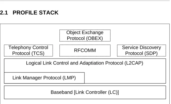
2.1 PROFILE STACK
Figure 2.1: Profile stack covered by this profile.
The main purpose of this profile is to describe the use of the lower layers of the Bluetooth protocol stack (LC and LMP). To describe security related alterna- tives, also higher layers (L2CAP, RFCOMM and OBEX) are included.
2.2 CONFIGURATIONS AND ROLES
For the descriptions in this profile of the roles that the two devices involved in a Bluetooth communication can take, the generic notation of the A-party (the paging device in case of link establishment, or initiator in case of another pro- cedure on an established link) and the B-party (paged device or acceptor) is used. The A-party is the one that, for a given procedure, initiates the establish- ment of the physical link or initiates a transaction on an existing link.
This profile handles the procedures between two devices related to discovery and connecting (link and connection establishment) for the case where none of the two devices has any link established as well as the case where (at least) one device has a link established (possibly to a third device) before starting the described procedure.
Logical Link Control and Adaptiation Protocol (L2CAP)
Baseband [Link Controller (LC)]
Link Manager Protocol (LMP) Telephony Control
Protocol (TCS) RFCOMM Service Discovery
Protocol (SDP) Object Exchange
Protocol (OBEX)
Profile overview 1 December 1999 23
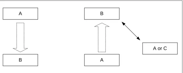
Figure 2.2: This profile covers procedures initiated by one device (A) towards another device (B) that may or may not have an existing Bluetooth link active.
The initiator and the acceptor generally operate the generic procedures
according to this profile or another profile referring to this profile. If the acceptor operates according to several profiles simultaneously, this profile describes generic mechanisms for how to handle this.
2.3 USER REQUIREMENTS AND SCENARIOS
The Bluetooth user should in principle be able to connect a Bluetooth device to any other Bluetooth device. Even if the two connected devices don’t share any common application, it should be possible for the user to find this out using basic Bluetooth capabilities. When the two devices do share the same applica- tion but are from different manufacturers, the ability to connect them should not be blocked just because manufacturers choose to call basic Bluetooth capabil- ities by different names on the user interface level or implement basic proce- dures to be executed in different orders.
2.4 PROFILE FUNDAMENTALS
This profile states the requirements on names, values and coding schemes used for names of parameters and procedures experienced on the user inter- face level.
This profile defines modes of operation that are not service- or profile-specific, but that are generic and can be used by profiles referring to this profile, and by devices implementing multiple profiles.
This profile defines the general procedures that can be used for discovering identities, names and basic capabilities of other Bluetooth devices that are in a mode where they can be discoverable. Only procedures where no channel or connection establishment is used are specified.
This profile defines the general procedure for how to create bonds (i.e. dedi- cated exchange of link keys) between Bluetooth devices.
A
B
B
A
A or C
24 1 December 1999 Profile overview
This profile describes the general procedures that can be used for establishing connections to other Bluetooth devices that are in mode that allows them to accept connections and service requests.
2.5 CONFORMANCE
Bluetooth devices that do not conform to any other Bluetooth profile shall con- form to this profile to ensure basic interoperability and co-existence.
Bluetooth devices that conform to another Bluetooth profile may use adapta- tions of the generic procedures as specified by that other profile. They shall, however, be compatible with devices compliant to this profile at least on the level of the supported generic procedures.
If conformance to this profile is claimed, all capabilities indicated mandatory for this profile shall be supported in the specified manner (process-mandatory).
This also applies for all optional and conditional capabilities for which support is indicated. All mandatory capabilities, and optional and conditional capabilities for which support is indicated, are subject to verification as part of the Blue- tooth certification program.
User interface aspects 1 December 1999 25
3 USER INTERFACE ASPECTS
3.1 THE USER INTERFACE LEVEL
In the context of this specification, the user interface level refers to places (such as displays, dialog boxes, manuals, packaging, advertising, etc.) where users of Bluetooth devices encounters names, values and numerical represen- tation of Bluetooth terminology and parameters.
This profile specifies the generic terms that should be used on the user inter- face level. These terms should be translated into languages supported by the Bluetooth device according to tables provided by the Bluetooth SIG.
3.2 REPRESENTATION OF BLUETOOTH PARAMETERS
3.2.1 Bluetooth device address (BD_ADDR)3.2.1.1 Definition
BD_ADDR is the unique address of a Bluetooth device as defined in [1]. It is received from a remote device during the device discovery procedure.
3.2.1.2 Term on user interface level
When the Bluetooth address is referred to on UI level, the term ’Bluetooth Device Address’ should be used.
3.2.1.3 Representation
On BB level the BD_ADDR is represented as 48 bits [1].
On the UI level the Bluetooth address shall be represented as 12 hexadecimal characters, possibly divided into sub-parts separated by’:’.
(E.g., ’000C3E3A4B69’ or ’00:0C:3E:3A:4B:69’.) At UI level, any number shall have the MSB -> LSB (from left to right) ’natural’ ordering (e.g., the number ’16’
shall be shown as ’0x10’).
3.2.2 Bluetooth device name (the user-friendly name)
3.2.2.1 Definition
The Bluetooth device name is the user-friendly name that a Bluetooth device presents itself with. It is a character string returned in LMP_name_res as response to a LMP_name_req.
26 1 December 1999 User interface aspects
3.2.2.2 Term on user interface level
When the Bluetooth device name is referred to on UI level, the term ’Bluetooth Device Name’ should be used.
3.2.2.3 Representation
The Bluetooth device name can be up to 248 bytes maximum according to [2].
It shall be coded according to Unicode UTF-8 (i.e. name entered on UI level may be down to 82 characters if UCS-2 is used).
A device can not expect that a general remote device is able to handle more than the first 40 characters of the Bluetooth device name. If a remote device has limited display capabilities, it may use only the first 20 characters.
3.2.3 Bluetooth passkey (Bluetooth PIN)
3.2.3.1 Definition
The Bluetooth PIN is used to authenticate two Bluetooth devices (that have not previously exchanged link keys) to each other and create a trusted relationship between them. The PIN is used in the pairing procedure (see Section 10.2) to generate the initial link key that is used for further authentication.
The PIN may be entered on UI level but may also be stored in the device; e.g.
in the case of a device without sufficient MMI for entering and displaying digits.
3.2.3.2 Terms at user interface level
When the Bluetooth PIN is referred to on UI level, the term ’Bluetooth Passkey’
should be used.
3.2.3.3 Representation
The Bluetooth PIN has different representations on different level. PINBB is used on baseband level, and PINUI is used on user interface level.
PINBB is the PIN used by [1] for calculating the initialization key during the pair- ing procedure. PINUI is the character representation of the PIN that is entered on UI level. The transformation between PINBB and PINUI shall be according to Unicode UTF-8.
According to [1], PINBB can be 128 bits (16 bytes). When PIN is entered on UI level (PINUI), it is to be coded into PINBB according to Unicode UTF-8 (i.e. if a
User interface aspects 1 December 1999 27
device supports entry of characters outside the Unicode range 0x00 - 0x7F, the maximum number of characters in the PINUI may be less than 16).
Examples:
All Bluetooth devices that support the bonding procedure and support PIN handling on UI level shall support UI level handling of PINs consisting of deci- mal digits. In addition, devices may support UI level handling of PINs consisting of general characters.
If a device has a fixed PIN (i.e. PIN is stored in the device and cannot be entered on UI level during pairing), the PIN shall be defined using decimal dig- its. A device that is expected to pair with a remote device that has restricted UI capabilities should ensure that the PIN can be entered on UI level as decimal digits.
3.2.4 Class of Device
3.2.4.1 Definition
Class of device is a parameter received during the device discovery procedure, indicating the type of device and which types of service that are supported.
3.2.4.2 Term on user interface level
The information within the Class of Device parameter should be referred to as
’Bluetooth Device Class’ (i.e. the major and minor device class fields) and
’Bluetooth Service Type’ (i.e. the service class field). The terms for the defined Bluetooth Device Types and Bluetooth Service Types are defined in [11].
When using a mix of information found in the Bluetooth Device Class and the Bluetooth Service Type, the term ’Bluetooth Device Type’ should be used.
3.2.4.3 Representation
The Class of device is a bit field and is defined in [11]. The UI-level representa- tion of the information in the Class of device is implementation specific.
User-entered code Corresponding PINBB[0..length-1]
(value as a sequence of octets in hexadecimal notation)
’0123’ length = 4, value = 0x30 0x31 0x32 0x33
’Ärlich’ length = 7, value = 0xC3 0x84 0x72 0x6C 0x69 0x63 0x68
28 1 December 1999 User interface aspects
3.3 PAIRING
Two procedures are defined that make use of the pairing procedure defined on LMP level (LMP-pairing, see Section 10.2). Either the user initiates the bonding procedure and enters the passkey with the explicit purpose of creating a bond (and maybe also a secure relationship) between two Bluetooth devices, or the user is requested to enter the passkey during the establishment procedure since the devices did not share a common link key beforehand. In the first case, the user is said to perform ’bonding (with entering of passkey)’ and in the second case the user is said to ’authenticate using the passkey’.
Modes 1 December 1999 29
4 MODES
4.1 DISCOVERABILITY MODES
With respect to inquiry, a Bluetooth device shall be either in non-discoverable mode or in a discoverable mode. (The device shall be in one, and only one, discoverability mode at a time.) The two discoverable modes defined here are called limited discoverable mode and general discoverable mode. Inquiry is defined in [1].
When a Bluetooth device is in non-discoverable mode it does not respond to inquiry.
A Bluetooth device is said to be made discoverable, or set into a discoverable mode, when it is in limited discoverable mode or in general discoverable mode.
Even when a Bluetooth device is made discoverable it may be unable to respond to inquiry due to other baseband activity [1]. A Bluetooth device that does not respond to inquiry for any of these two reasons is called a silent device.
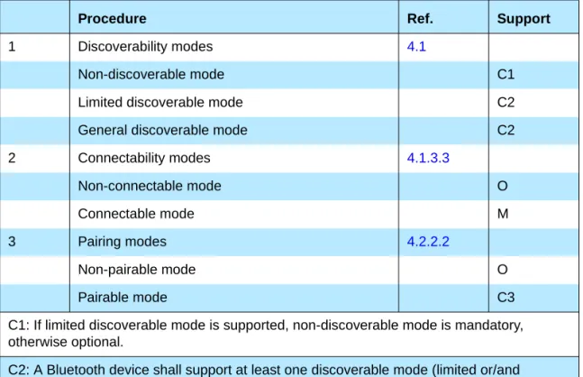
Procedure Ref. Support
1 Discoverability modes 4.1
Non-discoverable mode C1
Limited discoverable mode C2
General discoverable mode C2
2 Connectability modes 4.1.3.3
Non-connectable mode O
Connectable mode M
3 Pairing modes 4.2.2.2
Non-pairable mode O
Pairable mode C3
C1: If limited discoverable mode is supported, non-discoverable mode is mandatory, otherwise optional.
C2: A Bluetooth device shall support at least one discoverable mode (limited or/and general).
C3: If the bonding procedure is supported, support for pairable mode is mandatory, otherwise optional.
Table 4.1: Conformance requirements related to modes defined in this section
30 1 December 1999 Modes
After being made discoverable, the Bluetooth device shall be discoverable for at least TGAP(103).
4.1.1 Non-discoverable mode
4.1.1.1 Definition
When a Bluetooth device is in non-discoverable mode, it shall never enter the INQUIRY_RESPONSE state.
4.1.1.2 Term on UI-level
Bluetooth device is ’non-discoverable’ or in ’non-discoverable mode’.
4.1.2 Limited discoverable mode
4.1.2.1 Definition
The limited discoverable mode should be used by devices that need to be discoverable only for a limited period of time, during temporary conditions or for a specific event. The purpose is to respond to a device that makes a limited inquiry (inquiry using the LIAC).
A Bluetooth device should not be in limited discoverable mode for more than TGAP(104). The scanning for the limited inquiry access code can be done either in parallel or in sequence with the scanning of the general inquiry access code. When in limited discoverable mode, one of the following options shall be used.
4.1.2.1.1 Parallel scanning
When a Bluetooth device is in limited discoverable mode, it shall enter the INQUIRY_SCAN state at least once in TGAP(102) and scan for the GIAC and the LIAC for at least TGAP(101).
4.1.2.1.2 Sequential scanning
When a Bluetooth device is in limited discoverable mode, it shall enter the INQUIRY_SCAN state at least once in TGAP(102) and scan for the GIAC for at least TGAP(101) and enter the INQUIRY_SCAN state more often than once in TGAP(102) and scan for the LIAC for at least TGAP(101).
If an inquiry message is received when in limited discoverable mode, the entry into the INQUIRY_RESPONSE state takes precedence over the next entries into INQUIRY_SCAN state until the inquiry response is completed.
Modes 1 December 1999 31
4.1.2.2 Conditions
When a device is in limited discoverable mode it shall set bit no 13 in the Major Service Class part of the Class of Device/Service field [11].
4.1.2.3 Term on UI-level
Bluetooth device is ’discoverable’ or in ’discoverable mode’.
4.1.3 General discoverable mode
4.1.3.1 Definition
The general discoverable mode shall be used by devices that need to be discoverable continuously or for no specific condition. The purpose is to respond to a device that makes a general inquiry (inquiry using the GIAC).
4.1.3.2 Conditions
When a Bluetooth device is in general discoverable mode, it shall enter the INQUIRY_SCAN state more often than once in TGAP(102) and scan for the GIAC for at least TGAP(101).
A device in general discoverable mode shall not respond to a LIAC inquiry.
4.1.3.3 Term on UI-level
Bluetooth device is ’discoverable’ or in ’discoverable mode’.
4.2 CONNECTABILITY MODES
With respect to paging, a Bluetooth device shall be either in non-connectable mode or in connectable mode. Paging is defined in [1].
When a Bluetooth device is in non-connectable mode it does not respond to paging. When a Bluetooth device is in connectable mode it responds to paging.
4.2.1 Non-connectable mode
4.2.1.1 Definition
When a Bluetooth device is in non-connectable mode it shall never enter the PAGE_SCAN state.
32 1 December 1999 Modes
4.2.1.2 Term on UI-level
Bluetooth device is ’non-connectable’ or in ’non-connectable mode’.
4.2.2 Connectable mode
4.2.2.1 Definition
When a Bluetooth device is in connectable mode it shall periodically enter the PAGE_SCAN state.
4.2.2.2 Term on UI-level
Bluetooth device is ’connectable’ or in ’connectable mode’.
4.3 PAIRING MODES
With respect to pairing, a Bluetooth device shall be either in non-pairable mode or in pairable mode. In pairable mode the Bluetooth device accepts paring – i.e. creation of bonds – initiated by the remote device, and in non-pairable mode it does not. Pairing is defined in [1] and [2].
4.3.1 Non-pairable mode
4.3.1.1 Definition
When a Bluetooth device is in non-pairable mode it shall respond to a received LMP_in_rand with LMP_not_accepted with the reason pairing not allowed.
4.3.1.2 Term on UI-level
Bluetooth device is ’non-bondable’ or in ’non-bondable mode’ or “does not accept bonding”.
4.3.2 Pairable mode
4.3.2.1 Definition
When a Bluetooth device is in pairable mode it shall respond to a received LMP_in_rand with LMP_accepted (or with LMP_in_rand if it has a fixed PIN).
4.3.2.2 Term on UI-level
Bluetooth device is ’bondable’ or in ’bondable mode’ or “accepts bonding”.
Security aspects 1 December 1999 33
5 SECURITY ASPECTS
5.1 AUTHENTICATION
5.1.1 Purpose
The generic authentication procedure describes how the LMP-authentication and LMP-pairing procedures are used when authentication is initiated by one Bluetooth device towards another, depending on if a link key exists or not and if pairing is allowed or not.
5.1.2 Term on UI level
’Bluetooth authentication’.
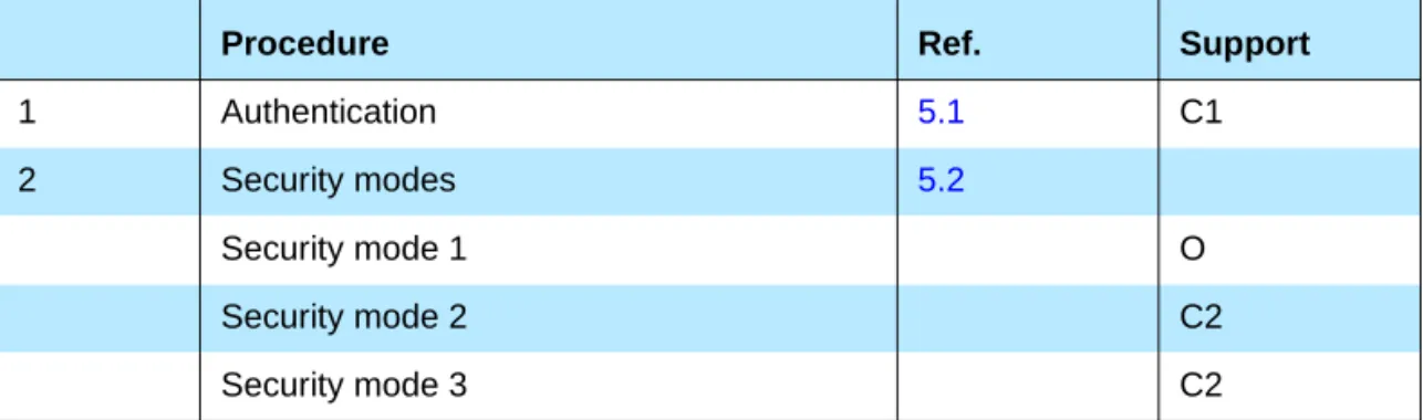
Procedure Ref. Support
1 Authentication 5.1 C1
2 Security modes 5.2
Security mode 1 O
Security mode 2 C2
Security mode 3 C2
C1: If security mode 1 is the only security mode that is supported, support for authentication is optional, otherwise mandatory. (Note: support for LMP-authentication and LMP-pairing is mandatory according [2] independent of which security mode that is used.)
C2: If security mode 1 is not the only security mode that is supported, then support for at least one of security mode 2 or security mode 3 is mandatory.
Table 5.1: Conformance requirements related to the generic authentication procedure and the security modes defined in this section
34 1 December 1999 Security aspects
5.1.3 Procedure
Figure 5.1: Definition of the generic authentication procedure.
5.1.4 Conditions
The device that initiates authentication has to be in security mode 2 or in security mode 3.
5.2 SECURITY MODES
The following flow chart describes where in the channel establishment proce- dures initiation of authentication takes place, depending on which security mode the Bluetooth device is in.
Authentication start
link authenticated
already?
link key available?
lmp_authentication
lmp_pairing Initiate pairing?
authentication ok authentication
failed
yes
no
yes
no
no
yes
fail
fail
ok
ok
Security aspects 1 December 1999 35
Figure 5.2: Illustration of channel establishment using different security modes.
Connectable mode
Paging
Link setup
LMP_host_co nnection_req
Query host
Device rejected?
LMP_not_
accepted
Authentication
Link setup complete
L2CAP_Conn ectReq
Query security DB
L2CAP_Conn ectRsp(-)
Authentication
L2CAP_Conn ectRsp(+) Encrypt
Encrypt Access?
Security mode 3
Security mode 1&2
Security mode 2
Security mode 1&3
yes, if auth rejected
yes no
LMP_accepted LMP_accepted
yes, no auth
36 1 December 1999 Security aspects
When authentication is initiated towards a Bluetooth device, it shall act accord- ing to [2] and the current pairing mode, independent of which security mode it is in.
5.2.1 Security mode 1 (non-secure)
When a Bluetooth device is in security mode 1 it shall never initiate any secu- rity procedure (i.e., it shall never send LMP_au_rand, LMP_in_rand or
LMP_encryption_mode_req).
5.2.2 Security mode 2 (service level enforced security)
When a Bluetooth device is in security mode 2 it shall not initiate any security procedure before a channel establishment request (L2CAP_ConnectReq) has been received or a channel establishment procedure has been initiated by itself. (The behavior of a device in security mode 2 is further described in [10].) Whether a security procedure is initiated or not depends on the security requirements of the requested channel or service.
A Bluetooth device in security mode 2 should classify the security requirements of its services using at least the following attributes:
• Authorization required;
• Authentication required;
• Encryption required.
Note: Security mode 1 can be considered (at least from a remote device point of view) as a special case of security mode 2 where no service has registered any security requirements.
5.2.3 Security modes 3 (link level enforced security)
When a Bluetooth device is in security mode 3 it shall initiate security proce- dures before it sends LMP_link_setup_complete. (The behavior of a device in security mode 3 is as described in [2].)
A Bluetooth device in security mode 3 may reject the host connection request (respond with LMP_not_accepted to the LMP_host_connection_req) based on settings in the host (e.g. only communication with pre-paired devices allowed).
Idle mode procedures 1 December 1999 37
6 IDLE MODE PROCEDURES
The inquiry and discovery procedures described here are applicable only to the device that initiates them (A). The requirements on the behavior of B is accord- ing to the modes specified in Section 4 and to [2].
6.1 GENERAL INQUIRY
6.1.1 Purpose
The purpose of the general inquiry procedure is to provide the initiator with the Bluetooth device address, clock, Class of Device and used page scan mode of general discoverable devices (i.e. devices that are in range with regard to the initiator and are set to scan for inquiry messages with the General Inquiry Access Code). Also devices in limited discoverable mode will be discovered using general inquiry.
The general inquiry should be used by devices that need to discover devices that are made discoverable continuously or for no specific condition.
6.1.2 Term on UI level
’Bluetooth Device Inquiry’.
Procedure Ref. Support
1 General inquiry 6.1 C1
2 Limited inquiry 6.2 C1
3 Name discovery 6.3 O
4 Device discovery 6.4 O
5 Bonding 6.5 O
C1: If initiation of bonding is supported, support for at least one inquiry procedure is manda- tory, otherwise optional.
(Note: support for LMP-pairing is mandatory [2].)
38 1 December 1999 Idle mode procedures
6.1.3 Description
Figure 6.1: General inquiry ,where B is a device in non-discoverable mode, B´ is a device in limited discoverable mode and B” is a device in general discoverable mode. (Note that all discoverable devices are discovered using general inquiry, independent of which discoverable mode they are in.)
6.1.4 Conditions
When general inquiry is initiated by a Bluetooth device, it shall be in the INQUIRY state for at least TGAP(100) and perform inquiry using the GIAC.
In order to receive inquiry response, the remote devices in range have to be made discoverable (limited or general).
6.2 LIMITED INQUIRY
6.2.1 Purpose
The purpose of the limited inquiry procedure is to provide the initiator with the Bluetooth device address, clock, Class of Device and used page scan mode of limited discoverable devices. The latter devices are devices that are in range with regard to the initiator, and may be set to scan for inquiry messages with the Limited Inquiry Access Code, in addition to scanning for inquiry messages with the General Inquiry Access Code.
The limited inquiry should be used by devices that need to discover devices that are made discoverable only for a limited period of time, during temporary conditions or for a specific event. Since it is not guaranteed that the
B"
B’
A B
Inquiry (GIAC)
inquiry_res
inquiry_res
list of Bluetooth
Device Addresses
Idle mode procedures 1 December 1999 39
discoverable device scans for the LIAC, the initiating device may choose any inquiry procedure (general or limited). Even if the remote device that is to be discovered is expected to be made limited discoverable (e.g. when a dedicated bonding is to be performed), the limited inquiry should be done in sequence with a general inquiry in such a way that both inquiries are completed within the time the remote device is limited discoverable, i.e. at least TGAP(103).
6.2.2 Term on UI level
’Bluetooth Device Inquiry’.
6.2.3 Description
Figure 6.2: Limited inquiry where B is a device in non-discoverable mode, B’ is a device in limited discoverable mode and B” is a device in general discoverable mode. (Note that only limited discoverable devices can be discovered using limited inquiry.)
6.2.4 Conditions
When limited inquiry is initiated by a Bluetooth device, it shall be in the INQUIRY state for at least TGAP(100) and perform inquiry using the LIAC.
In order to receive inquiry response, the remote devices in range has to be made limited discoverable.
B"
B’
A B
Inquiry (LIAC)
inquiry_res
list of Bluetooth
Device Addresses
40 1 December 1999 Idle mode procedures
6.3 NAME DISCOVERY
6.3.1 Purpose
The purpose of name discovery is to provide the initiator with the Bluetooth Device Name of connectable devices (i.e. devices in range that will respond to paging).
6.3.2 Term on UI level
’Bluetooth Device Name Discovery’.
6.3.3 Description
6.3.3.1 Name request
Name request is the procedure for retrieving the Bluetooth Device Name from a connectable Bluetooth device. It is not necessary to perform the full link establishment procedure (see Section 7.1) in order to just to get the name of another device.
Figure 6.3: Name request procedure.
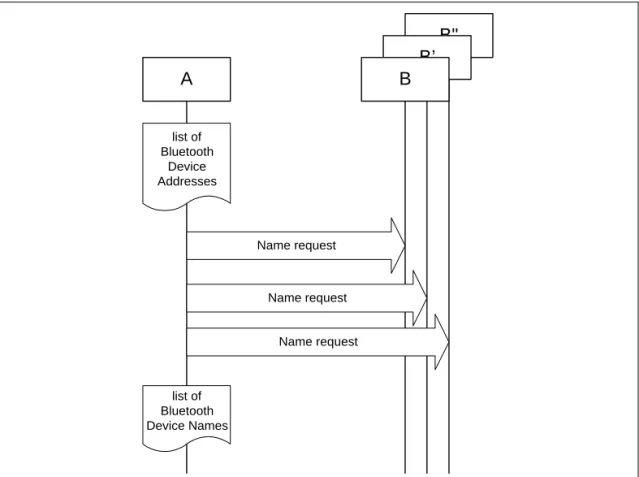
6.3.3.2 Name discovery
Name discovery is the procedure for retrieving the Bluetooth Device Name from connectable Bluetooth devices by performing name request towards known devices (i.e. Bluetooth devices for which the Bluetooth Device Addresses are available).
A B
Paging
LMP_name_req
LMP_name_res
LMP_detach
Idle mode procedures 1 December 1999 41
Figure 6.4: Name discovery procedure.
6.3.4 Conditions
In the name request procedure, the initiator will use the Device Access Code of the remote device as retrieved immediately beforehand – normally through an inquiry procedure.
6.4 DEVICE DISCOVERY
6.4.1 Purpose
The purpose of device discovery is to provide the initiator with the Bluetooth Address, clock, Class of Device, used page scan mode and Bluetooth device name of discoverable devices.
6.4.2 Term on UI level
’Bluetooth Device Discovery’.
B"
B’
A B
Name request
Name request Name request
list of Bluetooth Device Names
list of Bluetooth
Device Addresses
42 1 December 1999 Idle mode procedures
6.4.3 Description
During the device discovery procedure, first an inquiry (either general or lim- ited) is performed, and then name discovery is done towards some or all of the devices that responded to the inquiry.
Figure 6.5: Device discovery procedure.
6.4.4 Conditions
Conditions for both inquiry (general or limited) and name discovery must be ful- filled (i.e. devices discovered during device discovery must be both discover- able and connectable).
6.5 BONDING
6.5.1 Purpose
The purpose of bonding is to create a relation between two Bluetooth devices based on a common link key (a bond). The link key is created and exchanged (pairing) during the bonding procedure and is expected to be stored by both Bluetooth devices, to be used for future authentication.
In addition to pairing, the bonding procedure can involve higher layer initializa- tion procedures.
6.5.2 Term on UI level
’Bluetooth Bonding’
Name discovery
B"
B’
A B
Inquiry initiate
device discovery
list of discovered Bluetooth devices (Bluetooth Device Addresses)
make discoverable & connectable
list of discovered Bluetooth devices (Bluetooth Device Names)
Idle mode procedures 1 December 1999 43
6.5.3 Description
Two aspects of the bonding procedure are described here. Dedicated bonding is what is done when the two devices are explicitly set to perform only a cre- ation and exchange of a common link key.
General bonding is included to indicate that the framework for the dedicated bonding procedure is the same as found in the normal channel and connection establishment procedures. This means that pairing may be performed suc- cessfully if A has initiated bonding while B is in its normal connectable and security modes.
The main difference with bonding, as compared to a pairing done during link or channel establishment, is that for bonding it is the paging device (A) that must initiate the authentication.
6.5.3.1 General bonding
Figure 6.6: General description of bonding as being the link establishment procedure executed under specific conditions on both devices, followed by an optional higher layer initalization process.
A B
initiate bonding (BD_ADDR)
make pairable
Link establishment Delete link key to
paged device
Channel establishment
Higher layer initialisation
Channel release
LMP_detach update list of paired devices
44 1 December 1999 Idle mode procedures
6.5.3.2 Dedicated bonding
Figure 6.7: Bonding as performed when the purpose of the procedure is only to create and exchange a link key between two Bluetooth devices.
6.5.4 Conditions
Before bonding can be initiated, the initiating device (A) must know the Device Access Code of the device to pair with. This is normally done by first perform- ing device discovery. A Bluetooth Device that can initiate bonding (A) should use limited inquiry, and a Bluetooth Device that accepts bonding (B) should support the limited discoverable mode.
Bonding is in principle the same as link establishment with the conditions:
• The paged device (B) shall be set into pairable mode. The paging device (A) is assumed to allow pairing since it has initiated the bonding procedure.
• The paging device (the initiator of the bonding procedure, A) shall initiate authentication.
• Before initiating the authentication part of the bonding procedure, the paging device should delete any link key corresponding to a previous bonding with the paged device.
• If the paging device does not intend to initiate any higher layer initialization during bonding, it need not send LMP_host_request before initiating authentication.
Authentication Paging
A B
initiate bonding
LMP_host_connection_req LMP_accepted
make pairable
Delete link key to paged device
LMP_detach LMP_name_req LMP_name_res
Establishment procedures 1 December 1999 45
7 ESTABLISHMENT PROCEDURES
The establishment procedures defined here do not include any discovery part.
Before establishment procedures are initiated, the information provided during device discovery (in the FHS packet of the inquiry response or in the response to a name request) has to be available in the initiating device. This information is:
• The Bluetooth Device Address (BD_ADDR) from which the Device Access Code is generated;
• The system clock of the remote device;
• The page scan mode used by the remote device.
Additional information provided during device discovery that is useful for mak- ing the decision to initiate an establishment procedure is:
• The Class of device;
• The Device name.
7.1 LINK ESTABLISHMENT
7.1.1 Purpose
The purpose of the link establishment procedure is to establish a physical link (of ACL type) between two Bluetooth devices using procedures from [1] and [2].
7.1.2 Term on UI level
’Bluetooth link establishment’
Procedure Ref. Support
in A
Support in B
1 Link establishment 7.1 M M
2 Channel establishment 7.2 O M
3 Connection establishment 7.3 O O
Table 7.1: Establishment procedures
46 1 December 1999 Establishment procedures
7.1.3 Description
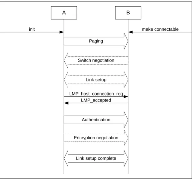
In this sub-section, the paging device (A) is in security mode 3. The paging device cannot during link establishment distinguish if the paged device (B) is in security mode 1 or 2.
7.1.3.1 B in security mode 1 or 2
Figure 7.1: Link establishment procedure when the paging device (A) is in security mode 3 and the paged device (B) is in security mode 1 or 2.
Encryption negotiation Authentication
Paging
A B
init
Link setup Switch negotiation
Link setup complete LMP_host_connection_req
LMP_accepted
make connectable
Establishment procedures 1 December 1999 47
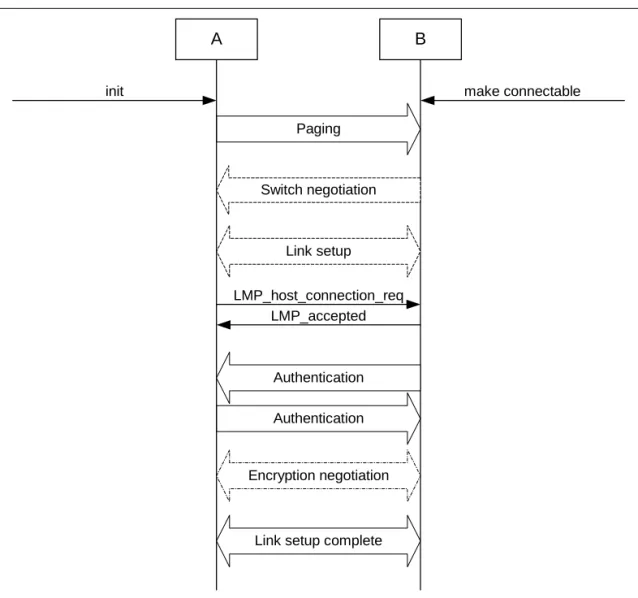
7.1.3.2 B in security mode 3
Figure 7.2: Link establishment procedure when both the paging device (A) and the paged device (B) are in security mode 3.
7.1.4 Conditions
The paging procedure shall be according to [1] and the paging device should use the Device access code and page mode received through a previous inquiry. When paging is completed, a physical link between the two Bluetooth devices is established.
If role switching is needed (normally it is the paged device that has an interest in changing the master/slave roles) it should be done as early as possible after the physical link is established. If the paging device does not accept the switch, the paged device has to consider whether to keep the physical link or not.
Both devices may perform link setup (using LMP procedures that require no interaction with the host on the remote side). Optional LMP features can be used after having confirmed (using LMP_feature_req) that the other device supports the feature.
Authentication Paging
A B
init
Link setup
Authentication Switch negotiation
Link setup complete Encryption negotiation LMP_host_connection_req
LMP_accepted
make connectable
48 1 December 1999 Establishment procedures
When the paging device needs to go beyond the link setup phase, it issues a request to be connected to the host of the remote device. If the paged device is in security mode 3, this is the trigger for initiating authentication.
The paging device shall send LMP_host_connection_req during link establish- ment (i.e. before channel establishment) and may initiate authentication only after having sent LMP_host_connection_request.
After an authentication has been performed, any of the devices can initiate encryption.
Further link configuration may take place after the LMP_host_connection_req.
When both devices are satisfied, they send LMP_setup_complete.
Link establishment is completed when both devices have sent LMP_setup_complete.
7.2 CHANNEL ESTABLISHMENT
7.2.1 Purpose
The purpose of the channel establishment procedure is to establish a Blue- tooth channel (a logical link) between two Bluetooth devices using [3].
7.2.2 Term on UI level
’Bluetooth channel establishment’.
7.2.3 Description
In this sub-section, the initiator (A) is in security mode 3. During channel establishment, the initiator cannot distinguish if the acceptor (B) is in security mode 1 or 3.
Establishment procedures 1 December 1999 49
7.2.3.1 B in security mode 2
Figure 7.3: Channel establishment procedure when the initiator (A) is in security mode 3 and the acceptor (B) is in security mode 2.
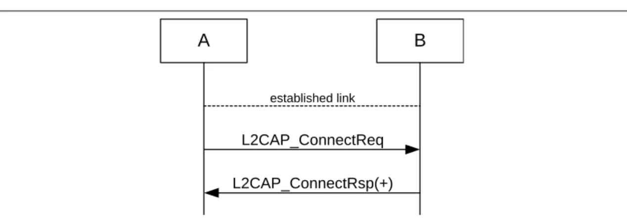
7.2.3.2 B in security mode 1 or 3
Figure 7.4: Channel establishment procedure when the initiator (A) is in security mode 3 and the acceptor (B) is in security mode 1 or 3.
7.2.4 Conditions
Channel establishment starts after link establishment is completed when the initiator sends a channel establishment request (L2CAP_ConnectReq).
Depending on security mode, security procedures may take place after the channel establishment has been initiated.
Channel establishment is completed when the acceptor responds to the chan- nel establishment request (with a positive L2CAP_ConnectRsp).
A B
L2CAP_ConnectReq
Authentication
Encryption negotiation L2CAP_ConnectRsp(+)
established link
A B
L2CAP_ConnectReq L2CAP_ConnectRsp(+)
established link
50 1 December 1999 Establishment procedures
7.3 CONNECTION ESTABLISHMENT
7.3.1 Purpose
The purpose of the connection establishment procedure is to establish a con- nection between applications on two Bluetooth devices.
7.3.2 Term on UI level
’Bluetooth connection establishment’
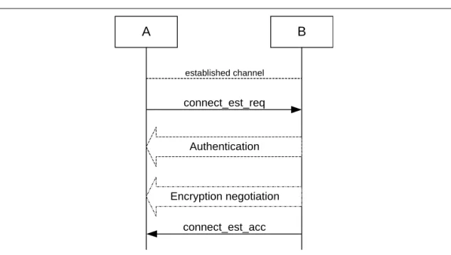
7.3.3 Description
In this sub-section, the initiator (A) is in security mode 3. During connection establishment, the initiator cannot distinguish if the acceptor (B) is in security mode 1 or 3.
7.3.3.1 B in security mode 2
Figure 7.5: Connection establishment procedure when the initiator (A) is in security mode 3 and the acceptor (B) is in security mode 2.
A B
connect_est_req
Authentication
Encryption negotiation connect_est_acc
established channel
Establishment procedures 1 December 1999 51
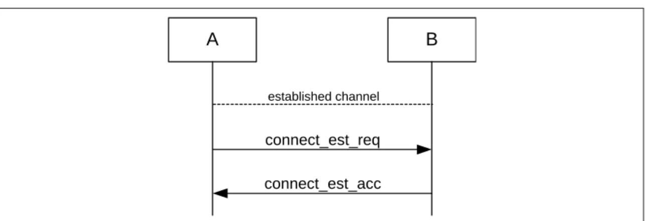
7.3.3.2 B in security mode 1 or 3
Figure 7.6: Connection establishment procedure when the initiator (A) is in security mode 3 and the acceptor (B) is in security mode 1 or 3.
7.3.4 Conditions
Connection establishment starts after channel establishment is completed, when the initiator sends a connection establishment request (’connect_est_req’
is application protocol-dependent). This request may be a TCS SETUP mes- sage [5] in the case of a Bluetooth telephony application Cordless Telephony Profile, or initialization of RFCOMM and establishment of DLC [4] in the case of a serial port-based application Serial Port Profile (although neither TCS or RFCOMM use the term ’connection’ for this).
Connection establishment is completed when the acceptor accepts the connection establishment request (’connect_est_acc’ is application protocol dependent).
7.4 ESTABLISHMENT OF ADDITIONAL CONNECTION
When a Bluetooth device has established one connection with another Bluetooth device, it may be available for establishment of:• A second connection on the same channel, and/or
• A second channel on the same link, and/or
• A second physical link.
If the new establishment procedure is to be towards the same device, the secu- rity part of the establishment depends on the security modes used. If the new establishment procedure is to be towards a new remote device, the device should behave according to active modes independent of the fact that it already has another physical link established (unless allowed co-incident radio and baseband events have to be handled).
A B
connect_est_req connect_est_acc
established channel
52 1 December 1999 Definitions
8 DEFINITIONS
In the following, terms written with capital letters refer to states.
8.1 GENERAL DEFINITIONS
Mode A set of directives that defines how a device will respond to certain events.
Idle As seen from a remote device, a Bluetooth device is idle, or is in idle mode, when there is no link established between them.
Bond A relation between two Bluetooth devices defined by creating, exchang- ing and storing a common link key. The bond is created through the bonding or LMP-pairing procedures.
8.2 CONNECTION-RELATED DEFINITIONS
Physical channel A synchronized Bluetooth baseband-compliant RF hopping sequence.
Piconet A set of Bluetooth devices sharing the same physical channel defined by the master parameters (clock and BD_ADDR).
Physical link A Baseband-level connection1 between two devices established using paging. A physical link comprises a sequence of transmission slots on a physical channel alternating between master and slave transmission slots.
ACL link An asynchronous (packet-switched) connection1 between two devices created on LMP level. Traffic on an ACL link uses ACL packets to be transmitted.
SCO link A synchronous (circuit-switched) connection1 for reserved bandwidth communications; e.g. voice between two devices, created on the LMP level by reserving slots periodically on a physical channel. Traffic on an SCO link uses SCO packets to be transmitted. SCO links can be established only after an ACL link has first been established.
Link Shorthand for an ACL link.
PAGE A baseband state where a device transmits page trains, and processes any eventual responses to the page trains.
PAGE_SCAN A baseband state where a device listens for page trains.
1. The term ’connection’ used here is not identical to the definition below. It is used in the absence of a more concise term.
Definitions 1 December 1999 53
Page The transmission by a device of page trains containing the Device Access Code of the device to which the physical link is requested.
Page scan The listening by a device for page trains containing its own Device Access Code.
Channel A logical connection on L2CAP level between two devices serving a single application or higher layer protocol.
Connection A connection between two peer applications or higher layer protocols mapped onto a channel.
Connecting A phase in the communication between devices when a connec- tion between them is being established. (Connecting phase follows after the link establishment phase is completed.)
Connect (to service) The establishment of a connection to a service. If not already done, this includes establishment of a physical link, link and channel as well.
8.3 DEVICE-RELATED DEFINITIONS
Discoverable device A Bluetooth device in range that will respond to an inquiry (normally in addition to responding to page).
Silent device A Bluetooth device appears as silent to a remote device if it does not respond to inquiries made by the remote device. A device may be silent due to being non-discoverable or due to baseband congestion while being discoverable.
Connectable device A Bluetooth device in range that will respond to a page.
Trusted device A paired device that is explicitly marked as trusted.
Paired device A Bluetooth device with which a link key has been exchanged (either before connection establishment was requested or during connecting phase).
Pre-paired device A Bluetooth device with which a link key was exchanged, and the link key is stored, before link establishment.
Un-paired device A Bluetooth device for which there was no exchanged link key available before connection establishment was request.
Known device A Bluetooth device for which at least the BD_ADDR is stored.
Un-known device A Bluetooth device for which no information (BD_ADDR, link key or other) is stored.