User’s Manual
(Hardware)
A1SJ71AP23Q, A1SJ71AR23Q A1SJ71AT23BQ
Thank you for purchasing the Mitsubishi programmable controller MELSEC-A series.
© 2007 MITSUBISHI ELECTRIC CORPORATION
MELSECNET, MELSECNET/B Local Station Data Link Module
Prior to use, please read this and relevant manuals thorougly to fully understand the product.
MODEL A1SJ71AP23Q-U-HW MODEL
CODE 13JY19
IB(NA)-0800372-B(0710)MEE
SAFETY PRECAUTIONS
(Always read these instructions before using this product)
Before using this product, please read this manual and the relevant manuals introduced in this manual carefully and pay full attention to safety to handle the product correctly.
The precautions given in this manual are concerned with this product only. For the safety precautions of the programmable controller system, please read the User's Manual for the CPU module used.
In this manual, the safety instructions are ranked as "DANGER" and "CAUTION".
Note that the CAUTION level may lead to a serious consequence according to the circumstances.
Always follow the instructions of both levels because they are important to personal safety.
Please save this manual to make it accessible when required and always forward it to the end user.
[DESIGN PRECAUTIONS]
DANGER
For each station's operating status in the case of a communication error in the network, refer to the MELSECNET, MELSECNET/B Local Station Data Link Module User's Manual. A malfunction due to a communication error may result in an accident.
DANGER
Indicates that incorrect handling may cause hazardous conditions, resulting in death or severe injury.Indicates that incorrect handling may cause hazardous conditions, resulting in medium or slight personal injury or physical damage.
CAUTION
[DESIGN PRECAUTIONS]
[INSTALLATION PRECAUTIONS]
DANGER
To control a running programmable controller (data modification) by connecting GX Developer to a CPU module or connecting a personal computer to an intelligent function module (special function module), create an interlock circuit on the sequence program so that the entire system will function safely all the time.
Also, before performing any other controls (e.g. program modification, operating status change (status control)) to the programmable controller, read the manual carefully and ensure the safety.
Especially, in the case of controlling a remotely-located programmable controller from an external device, a programmable controller side problem could not be resolved immediately due to data communication failure.
To prevent this, establish corrective procedures for communication failure between the external device and the programmable controller CPU, as well as creating an interlock circuit on the program.
CAUTION
Do not install the control lines and/or communication cables together with the main circuit or power cables, and also do not bring them close to each other.
Keep a distance of 100mm (3.94 inch) or more between them.
Failure to do so may cause a malfunction due to noise.
CAUTION
Use the programmable controller in the environment conditions given in the general specifications of the User's Manual for the CPU module used.
Failure to do so may cause an electric shock, fire, malfunction, or damage to or deterioration of the product.
Insert the module fixing projection into the module fixing hole in the base unit to mount the module. (For the AnS series module, fix it to the base unit with screws within the specified torque.)
Incorrect module mounting may cause a malfunction, failure, or drop of the module.
Be sure to shut off all phases of the external power supply used by the system before mounting or removing the module.
Failure to do so may damage the module.
Do not directly touch any conductive part or electronic component of the module. Doing so may cause a malfunction or failure of the module.
[WIRING PRECAUTIONS]
DANGER
Be sure to shut off all phases of the external power supply before installation or wiring.
Failure to do so may result in an electric shock or damage to the product.
CAUTION
Properly solder a connector for coaxial cable.
Failure to do so may cause malfunction.
Be careful to prevent foreign matter such as dust or wire chips from entering the module.
Failure to do so may cause a fire, failure or malfunction.
Be sure to place the communication cables or power cables in a duct or clamp them.
If not, dangling cables may swing or inadvertently be pulled, resulting in damage to the module or cables, or malfunctions due to poor cable contact.
When disconnecting a communication cable or power cable, do not pull it by holding the cable part.
To disconnect the cable, hold its connector that is plugged into the module.
Loosen screws for a terminal block before disconnecting a cable for connecting terminal block.
Pulling the cable part with the cable still connected to the module may damage the module and/or cable, or cause malfunctions due to poor cable contact.
[START-UP AND MAINTENANCE PRECAUTIONS]
[DISPOSAL PRECAUTIONS]
CAUTION
Do not disassemble or remodel each of the modules.
Doing so may cause failure, malfunctions, personal injuries and/or a fire.
When using a wireless communication device such as a mobile phone, keep a distance of 25cm (9.84inch) or more from the programmable controller in all directions.
Failure to do so may cause malfunctions.
Be sure to shut off all phases of the external power supply used by the system before mounting or removing the module.
Not doing so may damage the product.
Do not touch terminals during power-on.
Doing so may cause malfunctions.
Be sure to shut off all phases of the external power supply used by the system before cleaning or retightening the terminal screw or module mounting screw.
Not doing so may cause a failure or malfunction of the module.
If the screw is too loose, it may cause a drop, short circuit or malfunction.
Excessive tightening may cause damage to the screw and/or module, resulting in a drop, short circuit or malfunction.
Before handling the module, touch a grounded metal object to discharge the static electricity from the human body.
Not doing so may cause a failure or malfunction of the module.
CAUTION
When disposing of the product, treat it as industrial waste.
Revisions
* The manual number is given on the bottom right of the cover.
© 2007 MITSUBISHI ELECTRIC CORPORATION
Print Date *Manual Number Revision
Mar., 2007 IB(NA)-0800372-A First edition Oct., 2007 IB(NA)-0800372-B
Chapter 2
This manual confers no industrial property rights or any rights of any other kind, nor does it confer any patent licenses. Mitsubishi Electric Corporation cannot be held responsible for any problems involving industrial property rights which may occur as a result of using the contents noted in this manual.
Correction
CONTENTS
1. OVERVIEW... 1
2. PERFORMANCE SPECIFICATIONS ... 2
3. HANDLING ... 7
3.1 Handling Precautions ... 7
4. PART NAMES AND SETTINGS ... 8
5. WIRING... 11
5.1 Optical Fiber Cable... 12
5.2 Coaxial Cable ... 13
5.3 Shielded Twisted Pair Cable ... 16
6. EXTERNAL DIMENSIONS ... 17
6.1 A1SJ71AP23Q ... 17
6.2 A1SJ71AR23Q ... 18
6.3 A1SJ71AT23BQ ... 19
About Manuals
The following manuals are also related to this product.
Order them by referring to the table below as necessary.
A/QnA to Q conversion support tool (Version 1.02 or later) This is a tool to support the creation of a program for link data refresh and program for receiving the LRDP/LWTP instruction.
It can be downloaded from the MITSUBISHI ELECTRIC FA NETWORK SERVICE website free.
(http://www.MitsubishiElectric.co.jp/melfansweb) Compliance with the EMC and low voltage directives
When incorporating the Mitsubishi programmable controller into other machinery or equipment and keeping compliance with the EMC and low voltage directives, refer to Chapter 3 "EMC and Low Voltage Directives"
of the User's Manual (Hardware) included with the CPU module or base unit used.
The CE logo is printed on the rating plate of the programmable controller, indicating compliance with the EMC and low voltage directives.
To conform this product to the EMC and low voltage directives, refer to the Section "3.1.5 Precautions for use of the MELSEC-A series module"
in Chapter 3 "EMC and Low Voltage Directives" of the User's Manual (Hardware) included with the CPU module or base unit used.
Related manual
Manual name Manual No.
(Model code) MELSECNET, MELSECNET/B Local Station Data Link Module User's
Manual
SH-080670ENG (13JR98) Type MELSECNET, MELSECNET/B Data Link System Reference Manual IB-66350 (13JF70) For the use of this module, read MELSECNET, MELSECNET/B Local Station Data Link Module User's Manual and Type MELSECNET, MELSECNET/B Data Link System Reference Manual.
Support tool
1. OVERVIEW
This manual describes the specifications and part names of the data link module shown below used in the MELSECNET or MELSECNET/B data link system (hereinafter referred to as a local module).
• A1SJ71AP23Q type MELSECNET local station data link module • A1SJ71AR23Q type MELSECNET local station data link
module
• A1SJ71AT23BQ type MELSECNET/B local station data link module
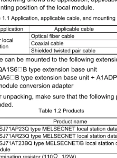
(1) The following shows the application, applicable cable, and mounting position of the local module.
*1 A local module can be mounted to the following extension base unit.
• QA1S6 B type extension base unit
• QA6 B type extension base unit + A1ADP-SP type A-A1S module conversion adapter
(2) After unpacking, make sure that the following products are included.
(3) The following shows the mountable CPU module and number of mountable modules for the local module
.
*2 Number of modules including the special function module compatible with A- series that can be mounted to the CPU module. For details, refer to the MELSECNET, MELSECNET/B Local Station Data Link Module User's Manual.
Table 1.1 Application, applicable cable, and mounting position
Model name Application Applicable cable Mounting position A1SJ71AP23Q
For local station
Optical fiber cable
I/O slot of extension base unit *1
A1SJ71AR23Q Coaxial cable
A1SJ71AT23BQ Shielded twisted pair cable
Table 1.2 Products
Model name Product name Quantity
A1SJ71AP23Q A1SJ71AP23Q type MELSECNET local station data link module 1 A1SJ71AR23Q A1SJ71AR23Q type MELSECNET local station data link module 1
A1SJ71AT23BQ
A1SJ71AT23BQ type MELSECNET/B local station data link
module 1
Terminating resistor (110 , 1/2W) 1
Table 1.3 Mountable CPU module and number of mountable modules Mountable CPU module Number of mountable modules
Q02/Q02H/Q06H/Q12H/Q25HCPU 6 *2
2. PERFORMANCE SPECIFICATIONS
This chapter describes the performance specifications of the MELSECNET or MELSECNET/B data link system and the local module.
For the general specifications, refer to the QCPU User's Manual (Hardware Design, Maintenance and Inspection).
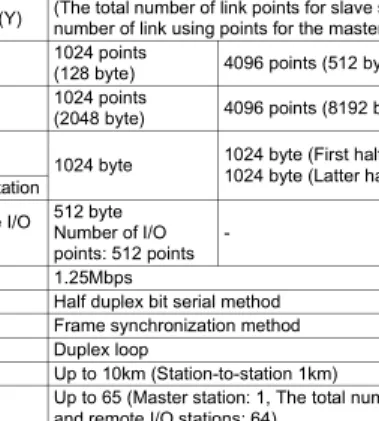
(1) Performance specifications of MELSECNET data link system and A1SJ71AP23Q
Table 2.1 Performance specifications of MELSECNET data link system and A1SJ71AP23Q
Item
Specifications MELSECNET data link system MELSECNET
mode MELSECNET II
mode MELSECNET II
composite mode Maximum
applicable link points per station
Input (X) Up to the maximum number of I/O points for the CPU module used in the master station is applicable.
(The total number of link points for slave station is equal to the number of link using points for the master station)
Output (Y)
Maximum link points in a system
B 1024 points
(128 byte) 4096 points (512 byte)
W 1024 points
(2048 byte) 4096 points (8192 byte)
Maximum link points per station
Master
station 1024 byte 1024 byte (First half of link parameters) 1024 byte (Latter half of link parameters) Local station
Remote I/O station
512 byte Number of I/O points: 512 points -
512 byte Number of I/O points: 512 points Communication speed 1.25Mbps
Communication method Half duplex bit serial method Synchronization method Frame synchronization method Transmission path Duplex loop
Overall cable distance Up to 10km (Station-to-station 1km) Number of connected
stations
Up to 65 (Master station: 1, The total number of local stations and remote I/O stations: 64)
Modulation method CMI method
Transmission format Conforming to HDLC (Frame format)
Error control system Retries due to CRC (generating polynomial X16+X12+X5+1) and time out
RAS function
• Loopback function due to error detection and cable break
• Diagnostic function including link line check of host station etc.
Connector 2-core optical connector plug (User prepared*1) Applicable cable Optical fiber cable (User prepared*1) Number of I/O occupied
points 32 points (Intelli: 32 points)
*1 Connecting an optical fiber cable with a connector requires professional skills and special tools. Also, a connector dedicated to an optical fiber cable is required.
For purchase, contact your local Mitsubishi Electric System Service or representative.
Internal current consumption
(5VDC) 0.33A
Weight 0.30kg
Table 2.1 Performance specifications of MELSECNET data link system and A1SJ71AP23Q(Continued)
Item
Specifications MELSECNET data link system MELSECNET
mode
MELSECNET II mode
MELSECNET II composite mode
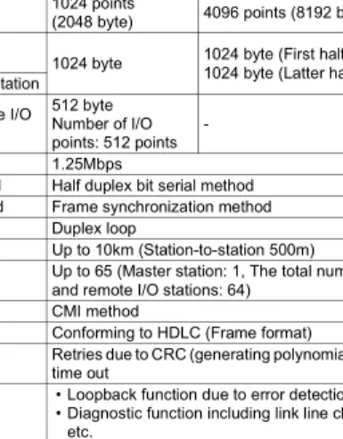
(2) Performance specifications of MELSECNET data link system and A1SJ71AR23Q
Table 2.2 Performance specifications of MELSECNET data link system and A1SJ71AR23Q
Item
Specifications MELSECNET data link system MELSECNET
mode MELSECNET II
mode MELSECNET II
composite mode Maximum
applicable link points per station
Input (X) Up to the maximum number of I/O points for the CPU module used in the master station is applicable.
(The total number of link points for slave station is equal to the number of link using points for the master station)
Output (Y)
Maximum link points in a system
B 1024 points
(128 byte) 4096 points (512 byte)
W 1024 points
(2048 byte) 4096 points (8192 byte)
Maximum link points per station
Master
station 1024 byte 1024 byte (First half of link parameters) 1024 byte (Latter half of link parameters) Local station
Remote I/O station
512 byte Number of I/O points: 512 points -
512 byte Number of I/O points: 512 points Communication speed 1.25Mbps
Communication method Half duplex bit serial method Synchronization method Frame synchronization method Transmission path Duplex loop
Overall cable distance Up to 10km (Station-to-station 500m) Number of connected
stations
Up to 65 (Master station: 1, The total number of local stations and remote I/O stations: 64)
Modulation method CMI method
Transmission format Conforming to HDLC (Frame format)
Error control system Retries due to CRC (generating polynomial X16+X12+X5+1) and time out
RAS function
• Loopback function due to error detection and cable break
• Diagnostic function including link line check of host station etc.
Connector
Connector plug for 3C-2V (User prepared):
• BNC-P-3-NiCAu-CF (DDK Ltd.) Connector plug for 5C-2V (User prepared):
• BNC-P-5-NiCAu-CF (DDK Ltd.)
• BNC-P-5DV SA(41) (HIROSE ELECTRIC CO., LTD.) Applicable cable Cables equivalent to 3C-2V or 5C-2V (User prepared) Number of I/O occupied
points 32 points (Intelli: 32 points) Internal current consumption
(5VDC) 0.80A
Weight 0.33kg
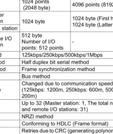
(3) Performance specifications of MELSECNET/B data link system and A1SJ71AT23BQ
Table 2.3 Performance specifications of MELSECNET/B data link system and A1SJ71AT23BQ
Item
Specifications MELSECNET/B data link system MELSECNET
mode MELSECNET II
mode MELSECNET II
composite mode Maximum
applicable link points per station
Input (X) Up to the maximum number of I/O points for the CPU module used in the master station is applicable.
(The total number of link points for slave station is equal to the number of link using points for the master station)
Output (Y)
Maximum link points in a system
B 1024 points
(128 byte) 4096 points (512 byte)
W 1024 points
(2048 byte) 4096 points (8192 byte)
Maximum link points per station
Master
station 1024 byte 1024 byte (First half of link parameters) 1024 byte (Latter half of link parameters) Local station
Remte I/O station
512 byte Number of I/O points: 512 points -
512 byte Number of I/O points: 512 points Communication speed 125kbps/250kbps/500kbps/1Mbps
Communication method Half duplex bit serial method Synchronization method Frame synchronization method Transmission path Bus method
Overall cable distance
Changed due to communication speed
(125kbps: 1200m, 250kbps: 600m, 500kbps: 400m, 1Mbps:
200m) Number of connected
stations
Up to 32 (Master station: 1, The total number of local stations and remote I/O stations: 31)
Modulation method NRZI method
Transmission format Conforming to HDLC (Frame format)
Error control system Retries due to CRC (generating polynomial X16+X12+X5+1) and time out
RAS function Diagnostic function including link line check of host station etc.
Connector Terminal block
Applicable cable Shielded twisted pair cable (User prepared) Number of I/O occupied
points 32 points (Intelli: 32 points) Internal current consumption
(5VDC) 0.66A
Weight 0.22kg
Remarks
Overall cable distance
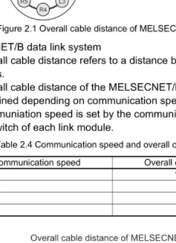
(1) MELSECNET data link system
The overall cable distance refers to a distance from OUT of the master station to IN of the master station via a slave station.
(2) MELSECNET/B data link system
The overall cable distance refers to a distance between stations at both ends.
The overall cable distance of the MELSECNET/B data link system is determined depending on communication speed.
The communiation speed is set by the communication speed setting switch of each link module.
Figure 2.1 Overall cable distance of MELSECNET
Table 2.4 Communication speed and overall cable distance Communication speed Overall cable distance
125kbps 1200m
250kbps 600m
500kbps 400m
1Mbps 200m
Figure 2.2 Overall cable distance of MELSECNET/B
L3 R4 R5 L6
M L1
R2 MELSECNET
Overall cable distance of MELSECNET
Overall cable distance of MELSECNET/B
L3
M L1 L2
3. HANDLING
[INSTALLATION PRECAUTIONS]
3.1 Handling Precautions
(1) Do not drop or give strong impact on the module, since its case is made of resin.
(2) Do not remove a printed-circuit board of the module from a case.
Doing so may cause failure.
(3) Be careful to prevent foreign matter such as wire chips from entering the module top at the time of wiring.
(4) Tighten a module mounting screw or a terminal screw within the following range.
CAUTION
Use the programmable controller in the environment conditions given in the general specifications of the User's Manual for the CPU module used.
Failure to do so may cause an electric shock, fire, malfunction, or damage to or deterioration of the product.
Insert the module fixing projection into the module fixing hole in the base unit to mount the module. (For the AnS series module, fix it to the base unit with screws within the specified torque.)
Incorrect module mounting may cause a malfunction, failure, or drop of the module.
Be sure to shut off all phases of the external power supply used by the system before mounting or removing the module.
Failure to do so may damage the module.
Do not directly touch any conductive part or electronic component of the module. Doing so may cause a malfunction or failure of the module.
Table 3.1 Screw tightening torque
Screw Tightening torque range
Terminal screw for cable terminal block (M3.5 screw) 59 to 88N•cm Mounting screw for cable terminal block (M3.5 screw) 59 to 88N•cm Module mounting screw (M4 screw) 78 to 118N•cm
4. PART NAMES AND SETTINGS
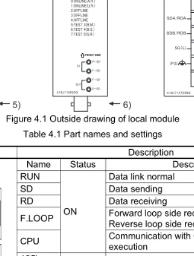
This chapter describes the part names and settings of the local module.
Figure 4.1 Outside drawing of local module Table 4.1 Part names and settings
No. Name Description
1)
LED Name Status Description
RUN
ON
Data link normal
SD Data sending
RD Data receiving
F.LOOP Forward loop side receives data (OFF:
Reverse loop side receives data) CPU Communication with CPU module in
execution 125k
ON Setting status of communication speed (A1SJ71AT23BQ)
250k 500k 1M CRC
ON (OFF if normal)
Code check error for receive data OVER The processing of receive data has been
delayed.
AB.IF
• "1" has been received consecutively more than stipulated times.
• Receive data length is shorter than stipulated length.
1) 1) 1)
2) 2)
2)
3) 3)
3) 4)
5) 6)
7)
1) LED (Continued) TIME
ON (OFF if normal)
Data link monitoring time is over.
DATA The data of error code has been received.
UNDER Internal processing of send data is not executed constantly.
UND.
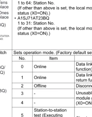
F.LOOP Receive error at forward loop side R.LOOP Receive error at reverse loop side 2) Station No. setting
switch
Sets station No. of the local module. (Factory default setting: 1)
• A1SJ71AP23Q/A1SJ71AR23Q 1 to 64: Station No.
(If other than above is set, the local module goes into offline status (X0=ON).)
• A1SJ71AT23BQ 1 to 31: Station No.
(If other than above is set, the local module goes into offline status (X0=ON).)
3) Mode setting switch Sets operation mode. (Factory default setting: 0)
No. Item Description
0 Online Data link (with automatic return function)
1 Online Data link (without automatic return function)
2 Offline Disconnects host station.
3 - Unusable (If set, the local
module goes into offline status (X0=ON).)
4 -
5 Station-to-station test (Executing
station) Checks a line between two adjacent stations.
6 Station-to-station test (Other station)
7 Self-loopback test
Checks the hardware including transmission circuit in a single local module.
8 to F -
Unusable (If set, the local module goes into offline status (X0=ON).)
Table 4.1 Part names and settings(Continued)
No. Name Description
Tens place Ones place
Tens place Ones place
(A1SJ71AP23Q/
A1SJ71AR23Q)
(A1SJ71AT23BQ)
(A1SJ71AP23Q/
A1SJ71AR23Q)
(A1SJ71AT23BQ)
4)
Communication speed setting switch (A1SJ71AT23BQ)
Sets communication speed.
No. Communication speed
0 125kbps
1 250kbps
2 500kbps
3 1Mbps
4 to F Unusable (If set, the local module goes into offline status (X0=ON).)
5)
Connector
(A1SJ71AP23Q) Connects an optical fiber cable.
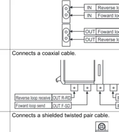
6)
Connector
(A1SJ71AR23Q) Connects a coaxial cable.
7)
Terminal block (A1SJ71AT23BQ)
Connects a shielded twisted pair cable.
Table 4.1 Part names and settings(Continued)
No. Name Description
Reverse loop send IN
IN Foward loop receive
Foward loop send OUT
Reverse loop receive OUT
IN R-SD IN F-RD OUT R-RD
OUT F-SD
Reverse loop send Foward loop receive Reverse loop receive
Foward loop send
5. WIRING
DANGER
Be sure to shut off all phases of the external power supply before installation or wiring.
Failure to do so may result in an electric shock or damage to the product.
CAUTION
Properly solder a connector for coaxial cable.
Failure to do so may cause malfunction.
Be careful to prevent foreign matter such as dust or wire chips from entering the module.
Failure to do so may cause a fire, failure or malfunction.
Be sure to place the communication cables or power cables in a duct or clamp them.
If not, dangling cables may swing or inadvertently be pulled, resulting in damage to the module or cables, or malfunctions due to poor cable contact.
When disconnect a communication cable or power cable, do not pull it by holding the cable part.
To disconnect the cable, hold its connector that is plugged into the module.
Loosen screws for a terminal block before disconnecting a cable for connecting terminal block.
Pulling the cable part with the cable still connected to the module may damage the module and/or cable, or cause malfunctions due to poor cable contact.
5.1 Optical Fiber Cable
This section describes how to connect an optical fiber cable with the local module.
(1) Precautions for wiring (a) Securing of wiring space
When an optical fiber cable is connected with the local module, a cable bend radius is restricted.
For details, check the specifications of the cable to be used.
(b) Laying an optical fiber cable
When laying an optical fiber cable, do not directly touch an optical fiber core of a plug or jack, and prevent dirt or dust from attaching it.
If oil from hand, dirt, or dust is attached, transmission loss may increase, resulting in failure at data link.
In addition, do not remove the cover from a connector of the module before installing an optical fiber cable.
(c) Installing/removing an optical fiber cable
Be sure to shut off all phases of the external power supply used by the system.
(2) Connection of cable
An optical fiber cable connects OUT and IN as shown below. (OUT of the last station is connected to IN of the master station.)
Figure 5.1 Connection method
OUT IN OUT IN
Front
OUT IN
Front Front
Master station Slave station
No.1
Station No. 00 Station
No. 01 Station
No. 02 Slave station
No.2
5.2 Coaxial Cable
This section describes how to connect a coaxial cable with the local module.
(1) Precautions for wiring (a) Securing of wiring space
When a coaxial cable is connected with the local module, a cable bend radius is restricted.
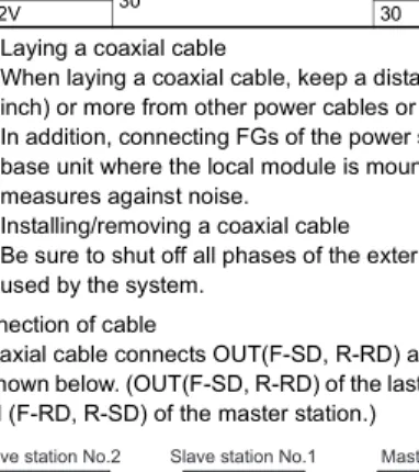
(b) Laying a coaxial cable
When laying a coaxial cable, keep a distance of 100mm (3.94 inch) or more from other power cables or control cables.
In addition, connecting FGs of the power supply module of the base unit where the local module is mounted strengthens measures against noise.
(c) Installing/removing a coaxial cable
Be sure to shut off all phases of the external power supply used by the system.
(2) Connection of cable
A coaxial cable connects OUT(F-SD, R-RD) and IN (F-RD, R-SD) as shown below. (OUT(F-SD, R-RD) of the last station is connected to IN (F-RD, R-SD) of the master station.)
Figure 5.2 Allowable bend radius of coaxial cable
Table 5.1 Allowable bend radius of coaxial cable
Applicable cable Connector part A(mm) Allowable bend radius r(mm) Coaxial cable 3C-2V
30 23
5C-2V 30
Figure 5.3 Connection method Local module A
r
Master station
Front
R-RD F-SD F-RD R-SD
IN OUT
R-RD F-SD F-RD R-SD
IN OUT
R-RD F-SD F-RD R-SD
IN OUT Slave station No.1
Front Slave station No.2
Station No. 02 Station No. 01 Station No. 00
Front
(3) Connection of cable for coaxial cable
The following shows how to connect a BNC connector (connector plug for coaxial cable) and a cable.
(a) Components of BNC connector and coaxial cable
Figure 5.4 Components of BNC connector and coaxial cable (b) How to connect BNC connector and coaxial cable
1) Remove external sheath of a coaxial cable as shown below.
Be careful not to damage an external conductor.
2) Put a nut, washer, gasket, and clamp through the coaxial cable and unravel the external conductor.
3) Cut the external conductor, insulator, and internal conductor in the following dimensions.
As for the external conductor, cut it in the same dimensions as taper part of the clamp, and smooth it down to the clamp.
Nut Washer Gasket
Clamp Contact Plug shell
Components of BNC connector
External sheath
External conductor Insulator
Internal conductor Components of coaxial cable
15mm (0.59 inch)
Measures for removing external sheath
Clamp
Gasket Washer
Nut
Internal conductor Insulator
Clamp and external conductor 3mm
(0.12inch) 6mm (0.24inch)
4) Solder a contact to the internal conductor.
5) Insert a contact assembly in 4) to a plug shell and screw a nut into the plug shell.
POINT
(1) When soldering an internal conductor and a contact, pay attention to the following points.
• Do not swell up the soldered part.
• Properly solder a contact and an insulator of the cable without making space between them or soldering them too tight.
• Perform soldering immediately so as not to modify the insulator.
(2) Before removing/mounting the coaxial cable connector, be sure to touch a grounded metal object to discharge the static electricity from the human body.
Not doing so may cause failure of the module.
Solderd
5.3 Shielded Twisted Pair Cable
This section describes how to connect a shielded twisted pair cable with the local module.
(1) Precautions for wiring
(a) Laying shielded twisted pair cable
When laying a shielded twisted pair cable, pay attention to the following points so that it will not be affected by noise or surge induction.
1) Do not install a shielded twisted pair cable together with the main circuit, high-voltage cable, or load line, and also do not bring them closer to each other. (Keep a distance of 100mm (3.94 inch) or more between them.)
2) Do not use a part of shielded twisted pair cable (for example, one pair among three pairs) as a cable for power supply.
(b) Connection of terminating resistor
For the stations at both ends of the MELSECNET/B data link system, connect SDA/RDA and SDB/RDB with an attahced terminating resistor (110 , 1/2W).
(c) Installing/removing shielded twisted pair cable
Be sure to shut off all phases of the external power supply used by the system.
(2) Connection of cable
A shielded twisted pair cable is connected as shown below.
In addition, use a terminating resistor for stations at both ends.
Figure 5.5 Connection method
SDA/RDA SDB/RDB SG(L)
FG
SDA/RDA SDB/RDB SG(L)
FG
SDA/RDA SDB/RDB SG(L)
FG
SDA/RDA SDB/RDB SG(L)
FG Terminating
resistor (110 1/2W)
Terminating resistor (110 1/2W)
Shielded twisted pair cable
6. EXTERNAL DIMENSIONS
6.1 A1SJ71AP23Q*1 For details, contact your local Mitsubishi Electric System Service or representative.
Unit: mm (inch) Figure 6.1 A1SJ71AP23Q
93.6
6.5 34.5
130
4.5 *1
Printed-circuit board
(0.26) (3.69) (1.36)
(5.12)
(0.18)
6.2 A1SJ71AR23Q
Unit: mm (inch) Figure 6.2 A1SJ71AR23Q
730
93.6 34.5 6.5
130
Printed-circuit board
(0.26) (3.69) (1.36)
(5.12)(0.28)(1.18)
6.3 A1SJ71AT23BQ
Unit: mm (inch) Figure 6.3 A1SJ71AT23BQ
71.6 (2.82) 6.5
130
34.5 93.6
14 Printed-circuit board
(0.26) (3.69)
(0.55) (1.36)
(5.12)
Warranty
Mitsubishi will not be held liable for damage caused by factors found not to be the cause of Mitsubishi; machine damage or lost profits caused by faults in the Mitsubishi products; damage, secondary damage, accident compensation caused by special factors unpredictable by Mitsubishi; damages to products other than Mitsubishi products; and to other duties.
For safe use
• This product has been manufactured as a general-purpose part for general industries, and has not been designed or manufactured to be incorporated in a device or system used in purposes related to human life.
• Before using the product for special purposes such as nuclear power, electric power, aerospace, medicine or passenger movement vehicles, consult with Mitsubishi.
• This product has been manufactured under strict quality control. However, when installing the product where major accidents or losses could occur if the product fails, install appropriate backup or failsafe functions in the system.
Country/Region Sales office/Tel
Specifications subject to change without notice.
Printed in Japan on recycled paper.
Country/Region Sales office/Tel
U.S.A Mitsubishi Electric Automation Inc.
500 Corporate Woods Parkway Vernon Hills, IL 60061
Tel : +1-847-478-2100 Brazil MELCO-TEC Rep. Com.e Assessoria
Tecnica Ltda.
Rua Correia Dias, 184, Edificio Paraiso Trade Center-8 andar Paraiso, Sao Paulo, SP Brazil Tel : +55-11-5908-8331
Germany Mitsubishi Electric Europe B.V. German Branch
Gothaer Strasse 8 D-40880 Ratingen, GERMANY
Tel : +49-2102-486-0 U.K Mitsubishi Electric Europe B.V. UK Branch
Travellers Lane, Hatfield, Herts., AL10 8XB,UK
Tel : +44-1707-276100 Italy Mitsubishi Electric Europe B.V. Italian Branch
Centro Dir. Colleoni, Pal. Perseo-Ingr.2 Via Paracelso 12, 20041 Agrate B.,
Milano, Italy
Tel : +39-039-6053344
Spain Mitsubishi Electric Europe B.V. Spanish Branch
Carretera de Rubi 76-80 08190 Sant Cugat del Valles,
Barcelona, Spain
Tel : +34-93-565-3131
France Mitsubishi Electric Europe B.V. French Branch
25 Boulevard des Bouvets, F-92741 Nanterre Cedex, France TEL: +33-1-5568-5568 South Africa Circuit Breaker Industries LTD.
Tripswitch Drive, Elandsfontein Gauteng,
South Africa
Tel : +27-11-928-2000
Hong Kong Ryoden Automation Ltd.
10th Floor, Manulife Tower, 169 Electric Road, North Point, HongKong Tel : +852-2887-8870 China Ryoden Automation Shanghai Ltd.
3F Block5 Building Automation Instrumentation Plaza 103 Cao Bao Rd.
Shanghai 200233 China Tel : +86-21-6120-0808 Taiwan Setsuyo Enterprise Co., Ltd.
6F., No.105 Wu-Kung 3rd.RD, Wu-Ku Hsiang, Taipei Hsine, Taiwan Tel : +886-2-2299-2499 Korea HAN NEUNG TECHNO CO.,LTD.
1F Dong Seo Game Channel Bldg., 660-11, Deungchon-dong Kangsec-ku,
Seoul, Korea
Tel : +82-2-3660-9552 Singapore Mitsubishi Electric Asia Pte, Ltd.
307 Alexandra Road #05-01/02, Mitsubishi Electric Building
Singapore 159943
Tel : +65-6473-2308 Thailand F. A. Tech Co.,Ltd.
898/28,29,30 S.V.City Building,Office Tower 2, Floor 17-18 Rama 3 Road,
Bangkpongpang, Yannawa,
Bangkok 10120
Tel : +66-2-682-6522
Indonesia P.T. Autoteknindo SUMBER MAKMUR Jl. Muara Karang Selatan Block a Utara No.1 Kav. No.11 Kawasan Industri/
Pergudangan Jakarta - Utara 14440 Tel : +62-21-663-0833 India Messung Systems Put,Ltd.
Electronic Sadan NO:111 Unit No15, M.I.D.C BHOSARI,PUNE-411026, India Tel : +91-20-712-2807
Australia Mitsubishi Electric Australia Pty. Ltd.
348 Victoria Road, PostalBag, No 2, Rydalmere, N.S.W 2116, Australia Tel : +61-2-9684-7777
HEAD OFFICE : 1-8-12, OFFICE TOWER Z 14F HARUMI CHUO-KU 104-6212, JAPAN NAGOYA WORKS : 1-14, YADA-MINAMI 5-CHOME, HIGASHI-KU, NAGOYA, JAPAN
When exported from Japan, this manual does not require application to the Ministry of Economy, Trade and Industry for service transaction permission.