External Axes
For KUKA System Software 5.5 and 5.6 Assembly and Operating Instructions
Issued: 15.02.2011
Version: KSS 5.5, 5.6 Zusatzachsen V1 en
长沙工控帮教育科技有限公司
© Copyright 2011 KUKA Roboter GmbH Zugspitzstraße 140 D-86165 Augsburg Germany
This documentation or excerpts therefrom may not be reproduced or disclosed to third parties without the express permission of KUKA Roboter GmbH.
Other functions not described in this documentation may be operable in the controller. The user has no claims to these functions, however, in the case of a replacement or service work.
We have checked the content of this documentation for conformity with the hardware and software described. Nevertheless, discrepancies cannot be precluded, for which reason we are not able to guarantee total conformity. The information in this documentation is checked on a regular basis, how- ever, and necessary corrections will be incorporated in the subsequent edition.
Subject to technical alterations without an effect on the function.
Translation of the original documentation KIM-PS5-DOC
Publication: Pub KSS 5.5, 5.6 Zusatzachsen en Bookstructure: KSS 5.5, 5.6 Zusatzachsen V1.1
长沙工控帮教育科技有限公司
1 Introduction ... 7
1.1 Target group ... 7
1.2 Industrial robot documentation ... 7
1.3 Representation of warnings and notes ... 7
1.4 Terms used ... 8
2 Fundamentals ... 9
2.1 Distinction between external axis and kinematic system ... 9
2.2 Kinematic system types ... 9
2.3 Motion types ... 11
2.4 Master/slave operation ... 13
3 Hardware ... 15
3.1 Maximum values for external axis systems ... 15
3.2 Top-mounted cabinet for external axes ... 16
3.3 Single Brake Module (SBM2) ... 17
3.3.1 Machine data ... 18
4 Safety ... 19
4.1 General ... 19
4.1.1 Liability ... 19
4.1.2 Intended use of the industrial robot ... 19
4.1.3 EC declaration of conformity and declaration of incorporation ... 20
4.1.4 Terms used ... 21
4.2 Personnel ... 21
4.3 Workspace, safety zone and danger zone ... 23
4.4 Triggers for stop reactions ... 23
4.5 Safety functions ... 24
4.5.1 Overview of safety functions ... 24
4.5.2 ESC safety logic ... 25
4.5.3 Mode selector switch ... 25
4.5.4 Operator safety ... 26
4.5.5 EMERGENCY STOP device ... 27
4.5.6 External EMERGENCY STOP device ... 28
4.5.7 Enabling device ... 28
4.5.8 External enabling device ... 29
4.6 Additional protective equipment ... 29
4.6.1 Jog mode ... 29
4.6.2 Software limit switches ... 29
4.6.3 Mechanical end stops ... 30
4.6.4 Mechanical axis range limitation (optional) ... 30
4.6.5 Axis range monitoring (optional) ... 30
4.6.6 Release device (optional) ... 31
4.6.7 KCP coupler (optional) ... 31
4.6.8 Labeling on the industrial robot ... 31
4.6.9 External safeguards ... 32
4.7 Overview of operating modes and safety functions ... 32
Contents
长沙工控帮教育科技有限公司
4.8 Safety measures ... 33
4.8.1 General safety measures ... 33
4.8.2 Testing safety-related controller components ... 34
4.8.3 Transportation ... 34
4.8.4 Start-up and recommissioning ... 35
4.8.5 Virus protection and network security ... 37
4.8.6 Manual mode ... 37
4.8.7 Simulation ... 38
4.8.8 Automatic mode ... 38
4.8.9 Maintenance and repair ... 38
4.8.10 Decommissioning, storage and disposal ... 40
4.8.11 Safety measures for “single point of control” ... 40
4.9 Applied norms and regulations ... 41
5 Operation ... 43
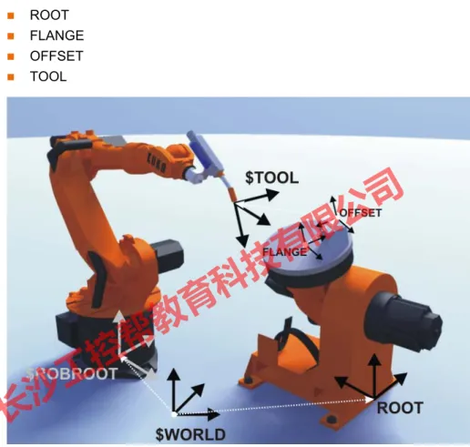
5.1 Coordinate systems ... 43
5.1.1 Kinematic chain with BASE kinematic system ... 43
5.1.2 Kinematic chain of a ROBROOT kinematic system ... 44
5.2 Jogging external axes ... 46
5.3 Mathematical coupling ... 47
5.3.1 Manually activating a mathematical coupling ... 47
5.3.2 Activating a mathematical coupling via a program ... 48
6 System planning ... 49
6.1 Planning external axis systems ... 49
7 Start-up and configuration ... 51
7.1 Starting up external axis systems ... 51
7.1.1 Starting up a KUKA linear unit ... 51
7.1.2 Starting up a KUKA kinematic system ... 51
7.1.3 Starting up a kinematic system with KUKA MGU ... 52
7.1.4 Starting up a kinematic system with KUKA motor ... 52
7.2 Machine data for external axes ... 53
7.3 Transformation ... 55
7.3.1 Machine data for configuration of the transformation ... 55
7.3.1.1 $EX_KIN ... 55
7.3.1.2 $ET1_AX ... 55
7.3.1.3 $ET1_NAME ... 56
7.3.1.4 $ET1_TA1KR ... 56
7.3.1.5 $ET1_TA2A1 ... 56
7.3.1.6 $ET1_TA3A2 ... 57
7.3.1.7 $ET1_TFLA3 ... 57
7.3.1.8 $ET1_TPINFL ... 57
7.3.2 Transformation of BASE kinematic system ... 58
7.3.3 Transformation of ROBROOT kinematic system ... 59
7.4 Optimizing machine data with the oscilloscope ... 60
7.4.1 Optimization sequence ... 60
7.4.2 Optimizing controller parameters ... 60
长沙工控帮教育科技有限公司
7.4.2.2 Optimizing $I_VEL_PTP and $I_VEL_CP ... 62
7.4.2.3 Optimizing $LG_PTP and $LG_CP ... 64
7.4.3 Optimizing acceleration parameters ... 66
7.4.3.1 Optimizing $RAISE_TIME ... 67
7.4.3.2 Optimizing $RED_ACC_EMX ... 68
7.4.3.3 Optimizing $DECEL_MB ... 69
7.4.3.4 Configuration examples ... 69
7.4.4 Checking the optimization results ... 71
7.4.5 Checking the r.m.s. current over a program cycle ... 72
7.5 Modifying machine data ... 72
7.5.1 Modifying individual machine data ... 72
7.5.2 Loading machine data via a text file ... 73
7.5.3 Modifying controller parameters ... 73
7.6 Axis configurator for external axes ... 73
7.6.1 Configuring machine data for external axes ... 75
7.6.2 Archiving a configuration ... 75
7.6.3 Loading a configuration ... 75
7.6.4 Creating a servo file ... 76
7.6.5 Loading a servo file ... 76
7.6.6 “General Data” tab ... 76
7.6.7 “External Axes” tab ... 77
7.6.8 “Main Axes” tab ... 77
7.6.9 “Ext. Kinematics” tab ... 77
7.6.10 “Servo-File” tab ... 78
8 System variables ... 79
8.1 System variables for configuring external axes ... 79
8.2 Enabling ... 79
8.2.1 $EXT_AXIS ... 79
8.2.2 $ASYNC_OPT ... 79
8.3 Asynchronous, uncoordinated external axes ... 80
8.3.1 $ZUST_ASYNC ... 80
8.3.2 $ASYNC_AX… ... 80
8.4 Asynchronous, coordinated external axes (ASYPTP) ... 81
8.4.1 $ASYNC_T1_FAST ... 81
8.4.2 $ASYNC_MODE ... 82
8.5 Decoupled external axes ... 83
8.5.1 $ASYNC_EX_AX_DECOUPLE ... 83
8.6 Permanently asynchronous external axes ... 84
8.6.1 $EX_AX_ASYNC ... 84
9 Programming ... 87
9.1 Programming motions for external axes ... 87
9.2 Programming synchronous external axes ... 87
9.2.1 Programming a mathematically coupled motion ... 88
9.3 Programming asynchronous external axes ... 88
9.3.1 $ASYNC_AXIS ... 88
9.3.2 ASYPTP ... 89
9.3.3 $OV_ASYNC ... 90
长沙工控帮教育科技有限公司
9.3.4 $ASYNC_FLT ... 91
9.3.5 ASYSTOP ... 91
9.3.6 ASYCONT ... 91
9.3.7 ASYCANCEL ... 92
9.3.8 $ASYNC_STATE ... 92
10 Examples ... 95
10.1 Transformation for DKP 400 ... 95
10.2 Transformation for KL 1500 ... 100
11 KUKA Service ... 103
11.1 Requesting support ... 103
11.2 KUKA Customer Support ... 103
Index ... 111
长沙工控帮教育科技有限公司
1 Introduction
1.1 Target group
This documentation is aimed at users with the following knowledge and skills:
Advanced knowledge of the robot controller system
Advanced KRL programming skills
1.2 Industrial robot documentation
The industrial robot documentation consists of the following parts:
Documentation for the manipulator
Documentation for the robot controller
Operating and programming instructions for the KUKA System Software
Documentation relating to options and accessories
Parts catalog on storage medium
Each of these sets of instructions is a separate document.
1.3 Representation of warnings and notes
Safety These warnings are relevant to safety and must be observed.
Hints These hints serve to make your work easier or contain references to further information.
For optimal use of our products, we recommend that our customers take part in a course of training at KUKA College. Information about the training program can be found at www.kuka.com or can be ob- tained directly from our subsidiaries.
These warnings mean that it is certain or highly probable that death or severe physical injury will occur, if no pre- cautions are taken.
These warnings mean that death or severe physical inju- ry may occur, if no precautions are taken.
These warnings mean that minor physical injuries may occur, if no precautions are taken.
These warnings mean that damage to property may oc- cur, if no precautions are taken.
These warnings contain references to safety-relevant information or general safety measures. These warnings do not refer to individual hazards or individual precautionary measures.
Tip to make your work easier or reference to further information.
长沙工控帮教育科技有限公司
1.4 Terms used
Term Description
DSE Digital Servo Electronics
KMC
KMC kinematic system
KUKA Motion Control
KUKA Motion Control can be used to control customer-specific kinematic systems.
KSD KUKA Servo Drive
KUKA.HMI Human/Machine Interface
KUKA.HMI is the KUKA user interface.
MFC3 Multi-function card
MGU Motor/gear unit
KUKA motor/gear combination for kinematic sys- tems
RDC Resolver Digital Converter
SBM2 Single Brake Module
Individual braking control for asynchronous external axes
长沙工控帮教育科技有限公司
2 Fundamentals
2.1 Distinction between external axis and kinematic system
The robot controller can control up to 6 external axes.
A kinematic system can consist of up to 3 external axes.
The robot controller can control up to 6 kinematic systems.
Areas of appli- cation
Kinematic systems are used if the robot has to work on a moving workpiece.
Kinematic systems extend the workspace of the robot, e.g. linear units, Cartesian gantries.
Kinematic systems improve the accessibility of the workpiece, e.g. two- axis positioner, positioner.
External axes are used if the robot is not working on the workpiece that has to be moved.
External axis that turns the workpiece ready for a subsequent operation, e.g. loading device
External axis as drive unit for tools, e.g. electric motor-driven welding gun (KUKA.ServoGun)
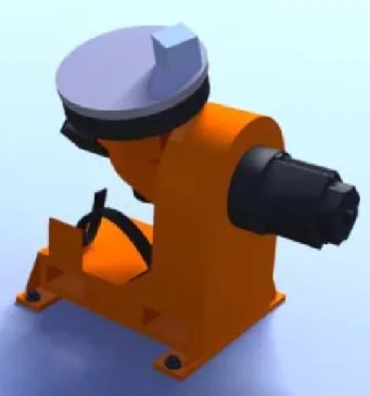
2.2 Kinematic system types
Overview The following kinematic system types are implemented by KUKA:
External ROBROOT kinematic system
External BASE kinematic system
External TOOL kinematic system ROBROOT
kinematic system
ROBROOT kinematic systems move the robot, e.g. the KUKA linear unit.
BASE kinematic system
BASE kinematic systems move the workpiece, e.g. two-axis positioner and positioner.
Fig. 2-1: Robot on linear unit
长沙工控帮教育科技有限公司
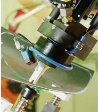
TOOL kinematic system
TOOL kinematic systems move the tool, e.g. the external adhesive nozzle for the application of adhesive to glass.
Fig. 2-2: Two-axis positioner
Fig. 2-3: Three-axis positioner
长沙工控帮教育科技有限公司
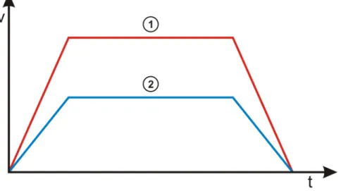
2.3 Motion types
Overview External axes can be moved synchronously or asynchronously to the robot ax- es. In order to execute asynchronous motions, external axes must be switched to asynchronous mode.
The following options are available for switching external axes to asynchro- nous mode:
KRL statement ASYPTP: can be used in the robot and submit interpreters and in interrupt programs.
(>>> 9.3.2 "ASYPTP" Page 89)
System variable $EX_AX_ASYNC (>>> 8.6.1 "$EX_AX_ASYNC" Page 84)
Asynchronous external axes cannot be moved asynchronously of one anoth- er. Simultaneous motions are possible, e.g.:
If 2 consecutive ASYPTP statements are programmed, the second motion does not start until the first motion has been completed, e.g.:
Synchronous In the case of a synchronous motion, all the axes involved (robot axes and ex- ternal axes) execute a common motion, starting simultaneously and stopping simultaneously. The axis position of the external axes is contained in every taught point (E6POS).
Fig. 2-4: External adhesive nozzle
Asynchronous external axes are not supported by an industrial robot with the SafeOperation option installed. Asynchronous external axes are treated like synchronous external axes by the SafeRDC.
...
ASYPTP {E1 90, E2 20}
...
...
ASYPTP {E1 90}
ASYPTP {E2 20}
...
长沙工控帮教育科技有限公司
Asynchronous In the case of an asynchronous motion, the external axes execute a motion that is not synchronized with the robot axes.
Fig. 2-5: Synchronous robot and external axis motion 1 Robot motion
2 Synchronous motion of an external axis Synchronous motions
Mathematically coupled Non-coupled The robot calculates its motion path
in relation to the position of the kinematic system.
The kinematic system must be cali- brated.
The robot calculates its motion path without taking the position of the external axis into consideration.
The external axis need not be cali- brated.
Example:
Turn-tilt table, positioner
KUKA linear unit
Note: A ROBROOT kinematic system is always mathematical- ly coupled and is not calibrated.
Example:
Electric motor-driven welding gun in program mode
Turnover positioner
长沙工控帮教育科技有限公司
Example
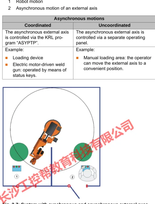
2.4 Master/slave operation
Description In master/slave operation, external axes can be driven by up to 6 motors. 1 master and up to 5 slaves.
There are 2 types of drive control in master/slave operation:
Position control
Torque control
The master motor is always position-controlled. The slave motors are either position-controlled or torque-controlled. Which variant is selected for the slave depends on the required mechanical stiffness between master and slave.
1 Robot motion
2 Asynchronous motion of an external axis Asynchronous motions
Coordinated Uncoordinated
The asynchronous external axis is controlled via the KRL pro- gram “ASYPTP”.
The asynchronous external axis is controlled via a separate operating panel.
Example:
Loading device
Electric motor-driven weld gun: operated by means of status keys.
Example:
Manual loading area: the operator can move the external axis to a convenient position.
Fig. 2-7: System with synchronous and asynchronous external axes 1 Mathematically coupled synchronous motion of robot and kinematic
system
2 Uncoordinated asynchronous motion of the external axis
长沙工控帮教育科技有限公司
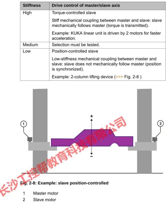
Stiffness Drive control of master/slave axis High Torque-controlled slave
Stiff mechanical coupling between master and slave: slave mechanically follows master (torque is transmitted).
Example: KUKA linear unit is driven by 2 motors for faster acceleration.
Medium Selection must be tested.
Low Position-controlled slave
Low-stiffness mechanical coupling between master and slave: slave does not mechanically follow master (position is synchronized).
Example: 2-column lifting device (>>> Fig. 2-8 )
Fig. 2-8: Example: slave position-controlled 1 Master motor
2 Slave motor
长沙工控帮教育科技有限公司
3 Hardware
3.1 Maximum values for external axis systems
Robot controller The robot controller can control up to 12 axes.
Up to 8 KSDs can be integrated into the robot controller.
KSDs 1 … 6 of the robot controller are assigned to the robot.
External axes In the case of a 6-axis robot, a maximum of 2 KSDs (KSD-08/16/32) or one double-sized KSD (KSD-48/64) for external axes can be integrated into the robot controller.
A top-mounted cabinet is used for 3 or more external axes.
The robot controller can control up to 6 kinematic systems.
A kinematic system can consist of up to 3 external axes, i.e. a second ro- bot cannot be operated as an external kinematic system.
Master/slave operation
One axis can be driven by up to 6 motors. (1 master and 1 to 5 slaves)
The robot controller can control up to 16 motors. (8 channels per DSE; 2 DSEs possible)
A maximum of 8 master/slave axes can be configured.
Every motor requires a KSD.
Master and slave motors must be assigned to the same braking channel.
Master/slave axes require a DSE-IBS-C33.
The KSDs of master/slave axes must be connected to the DSE without a gap.
The master motor and slave motors and their KSDs must all be of the same type.
Further information is contained in the assembly or operating instruc- tions for the robot controller.
Fig. 3-1: KSDs in the robot controller 1 KSDs for 2 external axes
2 KSDs for 6 robot axes
长沙工控帮教育科技有限公司
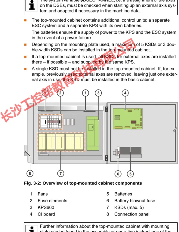
3.2 Top-mounted cabinet for external axes
Description The robot controller can directly supply a maximum of 8 KSDs or 4 double- width KSDs.
In the case of 3 or more external axes, a second RDC and a second KPS (KPS600) are required. These are located in the top-mounted cabinet.
In the case of 3 or more external axes, a DSE-IBS-AUX is additionally re- quired in the basic cabinet. The DSE-IBS-AUX (not of the same design as the DSE-IBS) is plugged onto the MFC3 in the basic cabinet.
The DSE-IBS-AUX is then the second DSE in the system.
All channels of the first RDC are assigned to the first DSE and all channels of the second RDC are assigned to the second DSE. The second RDC transfers the position signals of the external axes to the DSE-IBS-AUX.
The top-mounted cabinet contains additional control units: a separate ESC system and a separate KPS with its own batteries.
The batteries ensure the supply of power to the KPS and the ESC system in the event of a power failure.
Depending on the mounting plate used, a maximum of 5 KSDs or 3 dou- ble-width KSDs can be installed in the top-mounted cabinet.
If a top-mounted cabinet is used, all KSDs for external axes are installed there – if possible – and supplied by the same KPS.
A single KSD must not be installed in the top-mounted cabinet. If, for ex- ample, previously used external axes are removed, leaving just one exter- nal axis in use, the KSD must be installed in the basic cabinet.
Overview
The system variable $DSECHANNEL, i.e. the assignment of the axes on the DSEs, must be checked when starting up an external axis sys- tem and adapted if necessary in the machine data.
Fig. 3-2: Overview of top-mounted cabinet components
1 Fans 5 Batteries
2 Fuse elements 6 Battery blowout fuse
3 KPS600 7 KSDs (max. 5)
4 CI board 8 Connection panel
Further information about the top-mounted cabinet with mounting plate can be found in the assembly or operating instructions of the
长沙工控帮教育科技有限公司
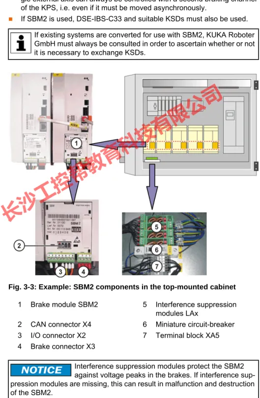
3.3 Single Brake Module (SBM2)
Description External axes must be switched to asynchronous mode to ensure a safe stop and protection against unexpected restarting. SBM2 is required for this.
Integration of the SBM2 into the KSDs allows the brakes of asynchronous ex- ternal axes to be controlled independently of the robot and the synchronous external axes.
All external axes supplied by the same KPS must be equipped and oper- ated with SBM2, even if only one of the external axes actually requires an SBM2.
If there is only one external axis in the system, no SBM2 is required. A sin- gle external axis can always be controlled with a second braking channel of the KPS, i.e. even if it must be moved asynchronously.
If SBM2 is used, DSE-IBS-C33 and suitable KSDs must also be used.
Overview
If existing systems are converted for use with SBM2, KUKA Roboter GmbH must always be consulted in order to ascertain whether or not it is necessary to exchange KSDs.
Fig. 3-3: Example: SBM2 components in the top-mounted cabinet 1 Brake module SBM2 5 Interference suppression
modules LAx
2 CAN connector X4 6 Miniature circuit-breaker
3 I/O connector X2 7 Terminal block XA5
4 Brake connector X3
Interference suppression modules protect the SBM2 against voltage peaks in the brakes. If interference sup- pression modules are missing, this can result in malfunction and destruction of the SBM2.
长沙工控帮教育科技有限公司
3.3.1 Machine data
$PMCHANNEL[ ] If there is a “1” before the value of a $PMCHANNEL variable, this axis module has an SBM2.
In the case of a industrial robot with 2 asynchronous external axes and SBM2, for example, the following could apply:
$PMCHANNEL[1] = 20
$PMCHANNEL[2] = 20
$PMCHANNEL[3] = 20
$PMCHANNEL[4] = 20
$PMCHANNEL[5] = 20
$PMCHANNEL[6] = 20
$PMCHANNEL[7] = 121
$PMCHANNEL[8] = 121
$BRK_MODE If SBM2s are used, the following applies:
$BRK_MODE = 1101
Further information about SBM2 can be found in the assembly or op- erating instructions of the top-mounted cabinet with mounting plate and in the documentation Single Brake Module for safety-oriented or non-safety-oriented applications.
长沙工控帮教育科技有限公司
4 Safety 4.1 General
4.1.1 Liability
The device described in this document is either an industrial robot or a com- ponent thereof.
Components of the industrial robot:
Manipulator
Robot controller
Teach pendant
Connecting cables
External axes (optional)
e.g. linear unit, turn-tilt table, positioner
Software
Options, accessories
The industrial robot is built using state-of-the-art technology and in accor- dance with the recognized safety rules. Nevertheless, misuse of the industrial robot may constitute a risk to life and limb or cause damage to the industrial robot and to other material property.
The industrial robot may only be used in perfect technical condition in accor- dance with its intended use and only by safety-conscious persons who are ful- ly aware of the risks involved in its operation. Use of the industrial robot is subject to compliance with this document and with the declaration of incorpo- ration supplied together with the industrial robot. Any functional disorders af- fecting the safety of the industrial robot must be rectified immediately.
Safety infor- mation
Safety information cannot be held against KUKA Roboter GmbH. Even if all safety instructions are followed, this is not a guarantee that the industrial robot will not cause personal injuries or material damage.
No modifications may be carried out to the industrial robot without the autho- rization of KUKA Roboter GmbH. Additional components (tools, software, etc.), not supplied by KUKA Roboter GmbH, may be integrated into the indus- trial robot. The user is liable for any damage these components may cause to the industrial robot or to other material property.
In addition to the Safety chapter, this document contains further safety instruc- tions. These must also be observed.
4.1.2 Intended use of the industrial robot
The industrial robot is intended exclusively for the use designated in the “Pur- pose” chapter of the operating instructions or assembly instructions.
Using the industrial robot for any other or additional purpose is considered im- permissible misuse. The manufacturer cannot be held liable for any damage resulting from such use. The risk lies entirely with the user.
Operating the industrial robot and its options within the limits of its intended use also involves observance of the operating and assembly instructions for
Further information is contained in the “Purpose” chapter of the oper- ating instructions or assembly instructions of the industrial robot.
长沙工控帮教育科技有限公司
the individual components, with particular reference to the maintenance spec- ifications.
Misuse Any use or application deviating from the intended use is deemed to be imper- missible misuse. This includes e.g.:
Transportation of persons and animals
Use as a climbing aid
Operation outside the permissible operating parameters
Use in potentially explosive environments
Operation without additional safeguards
Outdoor operation
4.1.3 EC declaration of conformity and declaration of incorporation
This industrial robot constitutes partly completed machinery as defined by the EC Machinery Directive. The industrial robot may only be put into operation if the following preconditions are met:
The industrial robot is integrated into a complete system.
Or: The industrial robot, together with other machinery, constitutes a com- plete system.
Or: All safety functions and safeguards required for operation in the com- plete machine as defined by the EC Machinery Directive have been added to the industrial robot.
The complete system complies with the EC Machinery Directive. This has been confirmed by means of an assessment of conformity.
Declaration of conformity
The system integrator must issue a declaration of conformity for the complete system in accordance with the Machinery Directive. The declaration of confor- mity forms the basis for the CE mark for the system. The industrial robot must be operated in accordance with the applicable national laws, regulations and standards.
The robot controller is CE certified under the EMC Directive and the Low Volt- age Directive.
Declaration of incorporation
The industrial robot as partly completed machinery is supplied with a declara- tion of incorporation in accordance with Annex II B of the EC Machinery Direc- tive 2006/42/EC. The assembly instructions and a list of essential
requirements complied with in accordance with Annex I are integral parts of this declaration of incorporation.
The declaration of incorporation declares that the start-up of the partly com- pleted machinery remains impermissible until the partly completed machinery has been incorporated into machinery, or has been assembled with other parts to form machinery, and this machinery complies with the terms of the EC Ma- chinery Directive, and the EC declaration of conformity is present in accor- dance with Annex II A.
The declaration of incorporation, together with its annexes, remains with the system integrator as an integral part of the technical documentation of the complete machinery.
长沙工控帮教育科技有限公司
4.1.4 Terms used
4.2 Personnel
The following persons or groups of persons are defined for the industrial robot:
User
Personnel
User The user must observe the labor laws and regulations. This includes e.g.:
The user must comply with his monitoring obligations.
The user must carry out instruction at defined intervals.
Personnel Personnel must be instructed, before any work is commenced, in the type of work involved and what exactly it entails as well as any hazards which may ex-
Term Description
Axis range Range of each axis, in degrees or millimeters, within which it may move.
The axis range must be defined for each axis.
Stopping distance Stopping distance = reaction distance + braking distance The stopping distance is part of the danger zone.
Workspace The manipulator is allowed to move within its workspace. The work- space is derived from the individual axis ranges.
Operator (User)
The user of the industrial robot can be the management, employer or delegated person responsible for use of the industrial robot.
Danger zone The danger zone consists of the workspace and the stopping distances.
KCP The KCP (KUKA Control Panel) teach pendant has all the operator con- trol and display functions required for operating and programming the industrial robot.
Manipulator The robot arm and the associated electrical installations Safety zone The safety zone is situated outside the danger zone.
Stop category 0 The drives are deactivated immediately and the brakes are applied. The manipulator and any external axes (optional) perform path-oriented braking.
Note: This stop category is called STOP 0 in this document.
Stop category 1 The manipulator and any external axes (optional) perform path-main- taining braking. The drives are deactivated after 1 s and the brakes are applied.
Note: This stop category is called STOP 1 in this document.
Stop category 2 The drives are not deactivated and the brakes are not applied. The manipulator and any external axes (optional) are braked with a normal braking ramp.
Note: This stop category is called STOP 2 in this document.
System integrator (plant integrator)
System integrators are people who safely integrate the industrial robot into a complete system and commission it.
T1 Test mode, Manual Reduced Velocity (<= 250 mm/s) T2 Test mode, Manual High Velocity (> 250 mm/s permissible)
External axis Motion axis which is not part of the manipulator but which is controlled using the robot controller, e.g. KUKA linear unit, turn-tilt table, Posiflex.
All persons working with the industrial robot must have read and un- derstood the industrial robot documentation, including the safety chapter.
长沙工控帮教育科技有限公司
ist. Instruction must be carried out regularly. Instruction is also required after particular incidents or technical modifications.
Personnel includes:
System integrator
Operators, subdivided into:
Start-up, maintenance and service personnel
Operating personnel
Cleaning personnel
System integrator The industrial robot is safely integrated into a complete system by the system integrator.
The system integrator is responsible for the following tasks:
Installing the industrial robot
Connecting the industrial robot
Performing risk assessment
Implementing the required safety functions and safeguards
Issuing the declaration of conformity
Attaching the CE mark
Creating the operating instructions for the complete system Operator The operator must meet the following preconditions:
The operator must be trained for the work to be carried out.
Work on the industrial robot must only be carried out by qualified person- nel. These are people who, due to their specialist training, knowledge and experience, and their familiarization with the relevant standards, are able to assess the work to be carried out and detect any potential hazards.
Example The tasks can be distributed as shown in the following table.
Installation, exchange, adjustment, operation, maintenance and re- pair must be performed only as specified in the operating or assembly instructions for the relevant component of the industrial robot and only by personnel specially trained for this purpose.
Tasks Operator Programmer System
integrator Switch robot controller
on/off x x x
Start program x x x
Select program x x x
Select operating mode x x x
Calibration
(tool, base) x x
Master the manipulator x x
Configuration x x
Programming x x
Start-up x
x
长沙工控帮教育科技有限公司
4.3 Workspace, safety zone and danger zone
Workspaces are to be restricted to the necessary minimum size. A workspace must be safeguarded using appropriate safeguards.
The safeguards (e.g. safety gate) must be situated inside the safety zone. In the case of a stop, the manipulator and external axes (optional) are braked and come to a stop within the danger zone.
The danger zone consists of the workspace and the stopping distances of the manipulator and external axes (optional). It must be safeguarded by means of physical safeguards to prevent danger to persons or the risk of material dam- age.
4.4 Triggers for stop reactions
Stop reactions of the industrial robot are triggered in response to operator ac- tions or as a reaction to monitoring functions and error messages. The follow- ing table shows the different stop reactions according to the operating mode that has been set.
Repair x
Decommissioning x
Transportation x
Work on the electrical and mechanical equipment of the industrial ro- bot may only be carried out by specially trained personnel.
Tasks Operator Programmer System
integrator
Fig. 4-1: Example of axis range A1
1 Workspace 3 Stopping distance
2 Manipulator 4 Safety zone
长沙工控帮教育科技有限公司
STOP 0, STOP 1 and STOP 2 are the stop definitions according to DIN EN 60204-1:2006.
4.5 Safety functions
4.5.1 Overview of safety functions
Safety functions:
Mode selection
Operator safety (= connection for the guard interlock)
Local EMERGENCY STOP device (= EMERGENCY STOP button on the KCP)
External EMERGENCY STOP device
Enabling device
External enabling device
Local safety stop via qualifying input
RoboTeam: disabling of robots that have not been selected
These circuits conform to the requirements of Performance Level d and cate- gory 3 according to EN ISO 13849-1. This only applies under the following conditions, however:
The EMERGENCY STOP is not triggered more than once a day on aver- age.
The operating mode is not changed more than 10 times a day on average.
Number of switching cycles of the main contactors: max. 100 per day
Trigger T1, T2 AUT, AUT
EXT
Safety gate opened - STOP 1
EMERGENCY STOP pressed STOP 0 STOP 1
Enabling withdrawn STOP 0 -
Start key released STOP 2 -
“Drives OFF” key pressed STOP 0
STOP key pressed STOP 2
Operating mode changed STOP 0
Encoder error
(DSE-RDC connection broken)
STOP 0
Motion enable canceled STOP 2
Robot controller switched off Power failure
STOP 0
If these conditions are not met, KUKA Roboter GmbH must be con- tacted.
In the absence of operational safety functions and safe- guards, the industrial robot can cause personal injury or material damage. If safety functions or safeguards are dismantled or deacti- vated, the industrial robot may not be operated.
长沙工控帮教育科技有限公司
4.5.2 ESC safety logic
The function and triggering of the electronic safety functions are monitored by the ESC safety logic.
The ESC (Electronic Safety Circuit) safety logic is a dual-channel computer- aided safety system. It permanently monitors all connected safety-relevant components. In the event of a fault or interruption in the safety circuit, the pow- er supply to the drives is shut off, thus bringing the industrial robot to a stand- still.
The ESC safety logic triggers different stop reactions, depending on the oper- ating mode of the industrial robot.
The ESC safety logic monitors the following inputs:
Operator safety
Local EMERGENCY STOP (= EMERGENCY STOP button on the KCP)
External EMERGENCY STOP
Enabling device
External enabling device
Drives OFF
Drives ON
Operating modes
Qualifying inputs
The ESC safety logic monitors the following outputs:
Operating mode
Drives ON
Local E-STOP
4.5.3 Mode selector switch
The industrial robot can be operated in the following modes:
Manual Reduced Velocity (T1)
Manual High Velocity (T2)
Automatic (AUT)
Automatic External (AUT EXT)
The operating mode is selected using the mode selector switch on the KCP.
The switch is activated by means of a key which can be removed. If the key is removed, the switch is locked and the operating mode can no longer be changed.
If the operating mode is changed during operation, the drives are immediately switched off. The manipulator and any external axes (optional) are stopped with a STOP 0.
长沙工控帮教育科技有限公司
4.5.4 Operator safety
The operator safety input is used for interlocking physical safeguards. Safety equipment, such as safety gates, can be connected to the dual-channel input.
If nothing is connected to this input, operation in Automatic mode is not possi- Fig. 4-2: Mode selector switch
1 T2 (Manual High Velocity) 2 AUT (Automatic)
3 AUT EXT (Automatic External) 4 T1 (Manual Reduced Velocity)
Operatin
g mode Use Velocities
T1
For test operation, pro- gramming and teach- ing
Program verification:
Programmed velocity, maxi- mum 250 mm/s
Jog mode:
Jog velocity, maximum 250 mm/
s
T2 For test operation Program verification:
Programmed velocity
AUT
For industrial robots without higher-level controllers
Only possible with a connected safety cir- cuit
Program mode:
Programmed velocity
Jog mode: Not possible
AUT EXT
For industrial robots with higher-level con- trollers, e.g. PLC Only possible with a connected safety cir- cuit
Program mode:
Programmed velocity
Jog mode: Not possible
长沙工控帮教育科技有限公司
ble. Operator safety is not active in the test modes T1 (Manual Reduced Ve- locity) and T2 (Manual High Velocity).
In the event of a loss of signal during Automatic operation (e.g. safety gate is opened), the manipulator and the external axes (optional) stop with a STOP 1.
Once the signal is active at the input again, automatic operation can be re- sumed.
Operator safety can be connected via the peripheral interface on the robot controller.
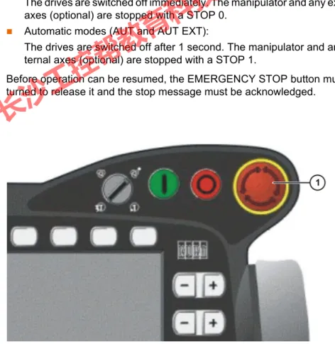
4.5.5 EMERGENCY STOP device
The EMERGENCY STOP device for the industrial robot is the EMERGENCY STOP button on the KCP. The button must be pressed in the event of a haz- ardous situation or emergency.
Reactions of the industrial robot if the EMERGENCY STOP button is pressed:
Manual Reduced Velocity (T1) and Manual High Velocity (T2) modes:
The drives are switched off immediately. The manipulator and any external axes (optional) are stopped with a STOP 0.
Automatic modes (AUT and AUT EXT):
The drives are switched off after 1 second. The manipulator and any ex- ternal axes (optional) are stopped with a STOP 1.
Before operation can be resumed, the EMERGENCY STOP button must be turned to release it and the stop message must be acknowledged.
It must be ensured that the operator safety signal is not automatically reset when the safeguard (e.g. safety gate) is closed, but only after an additional manual acknowledgement signal has been given. Only in this way can it be ensured that automatic operation is not resumed inadvertently while there are still persons in the danger zone, e.g.
due to the safety gate closing accidentally.
Failure to observe this precaution may result in death, severe physical inju- ries or considerable damage to property.
Fig. 4-3: EMERGENCY STOP button on the KCP
长沙工控帮教育科技有限公司
4.5.6 External EMERGENCY STOP device
There must be EMERGENCY STOP devices available at every operator sta- tion that can initiate a robot motion or other potentially hazardous situation.
The system integrator is responsible for ensuring this.
There must always be at least one external EMERGENCY STOP device in- stalled. This ensures that an EMERGENCY STOP device is available even when the KCP is disconnected.
External EMERGENCY STOP devices are connected via the customer inter- face. External EMERGENCY STOP devices are not included in the scope of supply of the industrial robot.
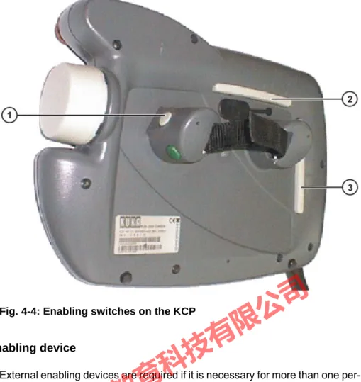
4.5.7 Enabling device
The enabling devices of the industrial robot are the enabling switches on the KCP.
There are 3 enabling switches installed on the KCP. The enabling switches have 3 positions:
Not pressed
Center position
Panic position
In the test modes, the manipulator can only be moved if one of the enabling switches is held in the central position. If the enabling switch is released or pressed fully down (panic position), the drives are deactivated immediately and the manipulator stops with a STOP 0.
Tools and other equipment connected to the manipulator must be integrated into the EMERGENCY STOP circuit on the system side if they could constitute a potential hazard.
Failure to observe this precaution may result in death, severe physical inju- ries or considerable damage to property.
The enabling switches must not be held down by adhe- sive tape or other means or manipulated in any other way.
Death, serious physical injuries or major damage to property may result.
长沙工控帮教育科技有限公司
4.5.8 External enabling device
External enabling devices are required if it is necessary for more than one per- son to be in the danger zone of the industrial robot. They can be connected via the peripheral interface on the robot controller.
External enabling devices are not included in the scope of supply of the indus- trial robot.
4.6 Additional protective equipment
4.6.1 Jog mode
In the operating modes T1 (Manual Reduced Velocity) and T2 (Manual High Velocity), the robot controller can only execute programs in jog mode. This means that it is necessary to hold down an enabling switch and the Start key in order to execute a program.
If the enabling switch is released or pressed fully down (panic position), the drives are deactivated immediately and the manipulator and any external axes (optional) stop with a STOP 0.
Releasing only the Start key causes the industrial robot to be stopped with a STOP 2.
4.6.2 Software limit switches
The axis ranges of all manipulator and positioner axes are limited by means of adjustable software limit switches. These software limit switches only serve as machine protection and must be adjusted in such a way that the manipulator/
positioner cannot hit the mechanical end stops.
Fig. 4-4: Enabling switches on the KCP
长沙工控帮教育科技有限公司
The software limit switches are set during commissioning of an industrial ro- bot.
4.6.3 Mechanical end stops
The axis ranges of main axes A1 to A3 and wrist axis A5 of the manipulator are limited by means of mechanical end stops with buffers.
Additional mechanical end stops can be installed on the external axes.
4.6.4 Mechanical axis range limitation (optional)
Some manipulators can be fitted with mechanical axis range limitation in axes A1 to A3. The adjustable axis range limitation systems restrict the working range to the required minimum. This increases personal safety and protection of the system.
In the case of manipulators that are not designed to be fitted with mechanical axis range limitation, the workspace must be laid out in such a way that there is no danger to persons or material property, even in the absence of mechan- ical axis range limitation.
If this is not possible, the workspace must be limited by means of photoelectric barriers, photoelectric curtains or obstacles on the system side. There must be no shearing or crushing hazards at the loading and transfer areas.
4.6.5 Axis range monitoring (optional)
Some manipulators can be fitted with dual-channel axis range monitoring sys- tems in main axes A1 to A3. The positioner axes may be fitted with additional axis range monitoring systems. The safety zone for an axis can be adjusted and monitored using an axis range monitoring system. This increases person- al safety and protection of the system.
Further information is contained in the operating and programming in- structions.
If the manipulator or an external axis hits an obstruction or a buffer on the mechanical end stop or axis range lim- itation, this can result in material damage to the industrial robot. KUKA Ro- boter GmbH must be consulted before the industrial robot is put back into operation. (>>> 11 "KUKA Service" Page 103)
The affected buffer must be replaced with a new one before operation of the industrial robot is resumed. If a manipulator (or external axis) collides with a buffer at more than 250 mm/s, the manipulator (or external axis) must be ex- changed or recommissioning must be carried out by KUKA Roboter GmbH.
This option is not available for all robot models. Information on spe- cific robot models can be obtained from KUKA Roboter GmbH.
This option is not available for all robot models. Information on spe- cific robot models can be obtained from KUKA Roboter GmbH.
长沙工控帮教育科技有限公司
4.6.6 Release device (optional)
Description The release device can be used to move the manipulator manually after an ac- cident or malfunction. The release device can be used for the main axis drive motors and, depending on the robot variant, also for the wrist axis drive mo- tors. It is only for use in exceptional circumstances and emergencies (e.g. for freeing people).
Procedure 1. Switch off the robot controller and secure it (e.g. with a padlock) to prevent unauthorized persons from switching it on again.
2. Remove the protective cap from the motor.
3. Push the release device onto the corresponding motor and move the axis in the desired direction.
The directions are indicated with arrows on the motors. It is necessary to overcome the resistance of the mechanical motor brake and any other loads acting on the axis.
4.6.7 KCP coupler (optional)
The KCP coupler allows the KCP to be connected and disconnected with the robot controller running.
4.6.8 Labeling on the industrial robot
All plates, labels, symbols and marks constitute safety-relevant parts of the in- dustrial robot. They must not be modified or removed.
Labeling on the industrial robot consists of:
Identification plates
Warning labels
Safety symbols
Designation labels
Cable markings
Rating plates
The motors reach temperatures during operation which can cause burns to the skin. Contact must be avoided.
Appropriate safety precautions must be taken, e.g. protective gloves must be worn.
Moving an axis with the release device can damage the motor brake. This can result in personal injury and mate- rial damage. After using the release device, the affected motor must be ex- changed.
The operator must ensure that decoupled KCPs are im- mediately removed from the system and stored out of sight and reach of personnel working on the industrial robot. This serves to prevent operational and non-operational EMERGENCY STOP facilities from becoming interchanged.
Failure to observe this precaution may result in death, severe physical inju- ries or considerable damage to property.
Further information is contained in the assembly or operating instruc- tions for the robot controller.
长沙工控帮教育科技有限公司
4.6.9 External safeguards
Safeguards The access of persons to the danger zone of the manipulator must be prevent- ed by means of safeguards.
Physical safeguards must meet the following requirements:
They meet the requirements of EN 953.
They prevent access of persons to the danger zone and cannot be easily circumvented.
They are sufficiently fastened and can withstand all forces that are likely to occur in the course of operation, whether from inside or outside the en- closure.
They do not, themselves, represent a hazard or potential hazard.
The prescribed minimum clearance from the danger zone is maintained.
Safety gates (maintenance gates) must meet the following requirements:
They are reduced to an absolute minimum.
The interlocks (e.g. safety gate switches) are linked to the operator safety input of the robot controller via safety gate switching devices or safety PLC.
Switching devices, switches and the type of switching conform to the re- quirements of Performance Level d and category 3 according to EN ISO 13849-1.
Depending on the risk situation: the safety gate is additionally safeguarded by means of a locking mechanism that only allows the gate to be opened if the manipulator is safely at a standstill.
The button for acknowledging the safety gate is located outside the space limited by the safeguards.
Other safety equipment
Other safety equipment must be integrated into the system in accordance with the corresponding standards and regulations.
4.7 Overview of operating modes and safety functions
The following table indicates the operating modes in which the safety functions are active.
Further information is contained in the technical data of the operating instructions or assembly instructions of the components of the indus- trial robot.
Further information is contained in the corresponding standards and regulations. These also include EN 953.
Safety functions T1 T2 AUT AUT EXT
Operator safety - - active active
EMERGENCY STOP
device active active active active
Enabling device active active - -
Reduced velocity during
program verification active - - -
长沙工控帮教育科技有限公司
4.8 Safety measures
4.8.1 General safety measures
The industrial robot may only be used in perfect technical condition in accor- dance with its intended use and only by safety-conscious persons. Operator errors can result in personal injury and damage to property.
It is important to be prepared for possible movements of the industrial robot even after the robot controller has been switched off and locked. Incorrect in- stallation (e.g. overload) or mechanical defects (e.g. brake defect) can cause the manipulator or external axes to sag. If work is to be carried out on a switched-off industrial robot, the manipulator and external axes must first be moved into a position in which they are unable to move on their own, whether the payload is mounted or not. If this is not possible, the manipulator and ex- ternal axes must be secured by appropriate means.
KCP The user must ensure that the industrial robot is only operated with the KCP by authorized persons.
If more than one KCP is used in the overall system, it must be ensured that each KCP is unambiguously assigned to the corresponding industrial robot.
They must not be interchanged.
External keyboard, external mouse
An external keyboard and/or external mouse may only be used if the following conditions are met:
Start-up or maintenance work is being carried out.
The drives are switched off.
There are no persons in the danger zone.
Jog mode active active - -
Software limit switches active active active active
Safety functions T1 T2 AUT AUT EXT
In the absence of operational safety functions and safe- guards, the industrial robot can cause personal injury or material damage. If safety functions or safeguards are dismantled or deacti- vated, the industrial robot may not be operated.
Standing underneath the robot arm can cause death or serious physical injuries. For this reason, standing un- derneath the robot arm is prohibited!
The motors reach temperatures during operation which can cause burns to the skin. Contact must be avoided.
Appropriate safety precautions must be taken, e.g. protective gloves must be worn.
The operator must ensure that decoupled KCPs are im- mediately removed from the system and stored out of sight and reach of personnel working on the industrial robot. This serves to prevent operational and non-operational EMERGENCY STOP facilities from becoming interchanged.
Failure to observe this precaution may result in death, severe physical inju- ries or considerable damage to property.
长沙工控帮教育科技有限公司
The KCP must not be used as long as an external keyboard and/or external mouse are connected.
The external keyboard and/or external mouse must be removed as soon as the start-up or maintenance work is completed or the KCP is connected.
Faults The following tasks must be carried out in the case of faults in the industrial robot:
Switch off the robot controller and secure it (e.g. with a padlock) to prevent unauthorized persons from switching it on again.
Indicate the fault by means of a label with a corresponding warning (tag- out).
Keep a record of the faults.
Eliminate the fault and carry out a function test.
Modifications After modifications to the industrial robot, checks must be carried out to ensure the required safety level. The valid national or regional work safety regulations must be observed for this check. The correct functioning of all safety circuits must also be tested.
New or modified programs must always be tested first in Manual Reduced Ve- locity mode (T1).
After modifications to the industrial robot, existing programs must always be tested first in Manual Reduced Velocity mode (T1). This applies to all compo- nents of the industrial robot and includes modifications to the software and configuration settings.
4.8.2 Testing safety-related controller components
All safety-related controller components are rated for a service life of 20 years (with the exception of the input/output terminals for safe bus systems). The controller components must nonetheless be tested regularly to ensure that they are still functional.
Check:
E-STOP pushbutton, mode selector switch
The E-STOP pushbutton and the mode selector switch must be actuated at least once every 6 months in order to detect any malfunction.
SafetyBUS Gateway outputs
If relays are switched on at an output, they must be switched off at least once every 6 months in order to detect any malfunction.
Additional checks are required during start-up and recommissioning.
(>>> 4.8.4 "Start-up and recommissioning" Page 35)
4.8.3 Transportation
Manipulator The prescribed transport position of the manipulator must be observed. Trans- portation must be carried out in accordance with the operating instructions or assembly instructions of the manipulator.
If input/output terminals are used in the robot controller for safe bus systems, these must be exchanged after 10 years at the latest. If this is not done, the integrity of the safety functions is not assured. This can result in death, physical injuries and damage to prop- erty.
长沙工控帮教育科技有限公司
Robot controller The robot controller must be transported and installed in an upright position.
Avoid vibrations and impacts during transportation in order to prevent damage to the robot controller.
Transportation must be carried out in accordance with the operating instruc- tions or assembly instructions of the robot controller.
External axis (optional)
The prescribed transport position of the external axis (e.g. KUKA linear unit, turn-tilt table, etc.) must be observed. Transportation must be carried out in ac- cordance with the operating instructions or assembly instructions of the exter- nal axis.
4.8.4 Start-up and recommissioning
Before starting up systems and devices for the first time, a check must be car- ried out to ensure that the systems and devices are complete and operational, that they can be operated safely and that any damage is detected.
The valid national or regional work safety regulations must be observed for this check. The correct functioning of all safety circuits must also be tested.
Interruptions/
cross-connec- tions
Interruptions or cross-connections affecting safety functions and not detected by the robot controller or SafeRDC must either be precluded (e.g. by the con- struction) or detected by the customer (e.g. by means of a PLC or by testing the outputs).
The passwords for logging onto the KUKA System Software as “Ex- pert” and “Administrator” must be changed before start-up and must only be communicated to authorized personnel.
The robot controller is preconfigured for the specific in- dustrial robot. If cables are interchanged, the manipula- tor and the external axes (optional) may receive incorrect data and can thus cause personal injury or material damage. If a system consists of more than one manipulator, always connect the connecting cables to the manipulators and their corresponding robot controllers.
If additional components (e.g. cables), which are not part of the scope of supply of KUKA Roboter GmbH, are integrated into the industrial robot, the user is responsible for ensuring that these components do not adversely affect or disable safety functions.
If the internal cabinet temperature of the robot controller differs greatly from the ambient temperature, condensa- tion can form, which may cause damage to the electrical components. Do not put the robot controller into operation until the internal temperature of the cabinet has adjusted to the ambient temperature.
Recommendation: design the construction in such a way as to pre- clude cross-connections. For this, observe the remarks in EN ISO 13849-2, tables D.5, D.6 and D.7.
长沙工控帮教育科技有限公司
Overview: possible cross-connections that are not detected by the robot controller or SafeRDC
Function test The following tests must be carried out before start-up and recommissioning:
General test:
It must be ensured that:
The industrial robot is correctly installed and fastened in accordance with the specifications in the documentation.
There are no foreign bodies or loose parts on the industrial robot.
All required safety equipment is correctly installed and operational.
The power supply ratings of the industrial robot correspond to the local supply voltage and mains type.
The ground conductor and the equipotential bonding cable are sufficiently rated and correctly connected.
The connecting cables are correctly connected and the connectors are locked.
Test of safety-oriented circuits:
A function test must be carried out for the following safety-oriented circuits to ensure that they are functioning correctly:
Local EMERGENCY STOP device (= EMERGENCY STOP button on the KCP)
External EMERGENCY STOP device (input and output)
Enabling device (in the test modes)
Operator safety (in the automatic modes)
Qualifying inputs (if connected)
All other safety-relevant inputs and outputs used Test of reduced velocity control:
This test is to be carried out as follows:
Cross-connection Possible in the case of
…
Cross-connection to 0 V ESC output Drives ON
ESC output E-STOP
Cross-connection to 24 V ESC output Drives ON
ESC output E-STOP
ESC output Operating Mode
SafeRDC inputs Cross-connection between the contacts of an
output
ESC output Drives ON
ESC output E-STOP
ESC output Operating Mode
Cross-connection between the contacts of different outputs
Cross-connection of an ESC output with an ESC input
Cross-connection between the channels of different ESC inputs
ESC inputs
Cross-connection between 2 SafeRDC inputs SafeRDC inputs Cross-connection of a SafeRDC output with a
SafeRDC input
SafeRDC outputs, Saf- eRDC inputs
长沙工控帮教育科技有限公司
2. Calculate the length of the path.
3. Execute the path in T1 mode with the override set to 100% and time the motion with a stopwatch.
4. Calculate the velocity from the length of the path and the time measured for execution of the motion.
Control of reduced velocity is functioning correctly if the following results are achieved:
The calculated velocity does not exceed 250 mm/s.
The robot executes the path as programmed (i.e. in a straight line, without deviations).
Machine data It must be ensured that the rating plate on the robot controller has the same machine data as those entered in the declaration of incorporation. The ma- chine data on the rating plate of the manipulator and the external axes (option- al) must be entered during start-up.
4.8.5 Virus protection and network security
The user of the industrial robot is responsible for ensuring that the software is always safeguarded with the latest virus protection. If the robot controller is in- tegrated into a network that is connected to the company network or to the In- ternet, it is advisable to protect this robot network against external risks by means of a firewall.
4.8.6 Manual mode
Manual mode is the mode for setup work. Setup work is all the tasks that have to be carried out on the industrial robot to enable automatic operation. Setup work includes:
Jog mode
Teaching
Programming
Program verification
The following must be taken into consideration in manual mode:
If the drives are not required, they must be switched off to prevent the ma- nipulator or the external axes (optional) from being moved unintentionally.
New or modified programs must always be tested first in Manual Reduced Velocity mode (T1).
The manipulator, tooling or external axes (optional) must never touch or project beyond the safety fence.
It must be ensured that no persons are present within the danger zone during path execution. Death or severe physical injuries may result.
The industrial robot must not be moved if incorrect ma- chine data are loaded. Death, severe physical injuries or considerable damage to property may otherwise result. The correct machine data must be loaded.
For optimal use of our products, we recommend that our customers carry out a regular virus scan. Information about security updates can be found at www.kuka.com.
长沙工控帮教育科技有限公司
Workpieces, tooling and other objects must not become jammed as a re- sult of the industrial robot motion, nor must they lead to short-circuits or be liable to fall off.
All setup work must be carried out, where possible, from outside the safe- guarded area.
If the setup work has to be carried out inside the safeguarded area, the follow- ing must be taken into consideration:
In Manual Reduced Velocity mode (T1):
If it can be avoided, there must be no other persons inside the safeguard- ed area.
If it is necessary for there to be several persons inside the safeguarded ar- ea, the following must be observed:
Each person must have an enabling device.
All persons must have an unimpeded view of the industrial robot.
Eye-contact between all persons must be possible at all times.
The operator must be so positioned that he can see into the danger area and get out of harm’s way.
In Manual High Velocity mode (T2):
This mode may only be used if the application requires a test at a velocity higher than Manual Reduced Velocity.
Teaching and programming are not permissible in this operating mode.
Before commencing the test, the operator must ensure that the enabling devices are operational.
The operator must be positioned outside the danger zone.
There must be no other persons inside the safeguarded area. It is the re- sponsibility of the operator to ensure this.
4.8.7 Simulation
Simulation programs do not correspond exactly to reality. Robot programs cre- ated in simulation programs must be tested in the system in Manual Reduced Velocity mode (T1). It may be necessary to modify the program.
4.8.8 Automatic mode
Automatic mode is only permissible in compliance with the following safety measures:
All safety equipment and safeguards are present and operational.
There are no persons in the system.
The defined working procedures are adhered to.
If the manipulator or an external axis (optional) comes to a standstill for no ap- parent reason, the danger zone must not be entered until an EMERGENCY STOP has been triggered.
4.8.9 Maintenance and repair
After maintenance and repair work, checks must be carried out to ensure the required safety level. The valid national or regional work safety regulations must be observed for this check. The correct functioning of all safety circuits must also be tested.