國立臺灣大學工學院化學工程學研究所 碩士論文
Department of Chemical Engineering College of Engineering
National Taiwan University Master Thesis
液態天然氣冷能應用於富氧燃燒 發電與二氧化碳捕捉系統之可行性分析
Feasibility Analysis of the Oxy-fuel Power Generation System with CO2 Capture using the Liquefied Natural Gas Cold Energy
王聰偉 Chong Wei Ong
指導教授:陳誠亮 博士 Advisor: Cheng-Liang Chen, Ph.D.
中華民國 109 年 7 月 July, 2020
誌謝
從2013 年 8 月來到台灣,至今已有七年。在這七年裡,我從僑生先修部結業,
在台大化工系取得學士學位,到現在從台大化工所畢業,取得碩士學位,過程中得 到許多人的幫助。首先,感謝一直以來支持我的家人,從不限制我,讓我自行選擇 未來的路的自由與空間,給我十足的勇氣大步邁前。因此,我才能夠在毫無顧慮的 環境底下,順利完成學業。接著,我想感謝曾經幫助過我的老師們,我的高中老師,
傅薔蓓老師、劉明華老師、陳盈穎老師,僑生先修部老師,孫佩玲老師、林世昌老 師、黃瑞玉老師,大學教授,陳賢燁教授、錢義隆教授、Jeff 教授以及對我幫助甚 多的指導教授,陳誠亮教授。
我永遠記得孫佩玲老師對我的鼓勵,老師希望我可以一直為自己的理想奮鬥,
這也因此給我許多前進的動力。我很慶幸,在大三升大四的暑假加入了程序系統工 程研究室,也認識了目前的指導教授陳誠亮老師。通過老師的指導,讓我學會將化 工系所學應用於研究上。因此,在此過程中我獲得了成就感,並且進一步愛上了化 工產業。三年的相處下來,可以感受到陳老師對於教學的熱忱以及提拔後輩的熱心。
我非常感激陳老師對我的指導與幫助。
另外,非常感謝老師提供一個非常優異且舒適的研究環境。同時,也感謝研究 室的同學,澤木直美、悰熺(口米)、堉暘、Vaishnav、張庭、嘉懿(老師),學長學姐,
冠辰(台柱)、晧人(阿面)、采薇、韋呈(小精靈)、少秋、向玹、立軒,學弟學妹,明 泓、婷睿、駿傑、士德(土德)等等,為研究室營造一個歡樂且輕鬆的氣氛,讓我們 能夠在一個自在的環境中,互相探討學術上的難題以及國內外政經社方面的議題。
接著,我要感謝兩位同學,溫翊均與吳文祺,在論文撰寫與英文修正上提供了許多 幫助。
最後,感謝我的口試委員,陳誠亮教授、錢義隆教授、Jeff 教授、李豪業教授 與李瑞元教授,在研究上提出許多充滿建設性的建議,讓我的研究進一步精進。請 容許我在最後的最後再次感謝我的指導教授,陳誠亮老師長久以來付出許多精神 與時間協助我完成本論文,謝謝大家。
中文摘要
全球各地液態天然氣(LNG)每年的進口總量持續提高,為了將進口燃料之能源 效率達到最大化以及降低液態天然氣氣化過程對環境的衝擊,液態天然氣氣化過 程所釋放之冷能量的回收與再利用受到各界的重視。Zhang et al. (2010) 提出一個 結合發電與液態天然氣氣化的雙循環系統 (COOLCEP-C) ,主要是利用液態天然 氣的冷能量,使得富氧燃燒的發電系統得以同時進行高效發電和二氧化碳捕捉。
COOLCEP-C 是一個類朗肯循環 (Rankine cycle) 的系統,將二氧化碳作為工 作流體 (working fluid),推動渦輪機以進行發電,同時液態天然氣作為此系統中的 冷能量來源用於液化二氧化碳,使得液態二氧化碳能夠使用能耗較低的加壓裝置 幫浦(Pump)進行加壓。在送入渦輪機前,首先氣化高壓的液態二氧化碳,而氣化過 程會吸收大量的熱能,亦可以為其他系統提供冷能量,高壓的氣態二氧化碳與氧氣 結合後送入燃燒器(Combustor),以提高通過渦輪機前後的氣體焓的變化(Enthalpy change)。接著,將水分去除後,液化二氧化碳,再將燃燒過程中所產生的二氧化 碳,進行分離捕捉(capture)。
但是,COOLCEP-C 系統中存在一些缺點。首先,二氧化碳捕捉的過程中將在
二氧化碳液化過程中排放的所有氣體進行加壓冷凝,而捕獲的二氧化碳濃度僅有 88.90 mol%, 需要後續的處理,故被認為是一個耗能且充滿疑慮的策略。接著,
Zhang et al. (2010) 中假設,除水器 (H2O Separator) 可以將混合氣體中的水蒸氣完 全分離,其工程技術可行性令人質疑。因此,本研究針對系統中的二氧化碳捕捉與
除水器進行改良。此外,本研究也將液態天然氣氣化循環中的操作壓力從73.5 bar
提高至150 bar, 同時新增一個天然氣渦輪機在此循環中,以提高系統的總發電量。
COOLCEP-C 經過改進後,命名為 MCOOLCEP-C。隨後,為了提高系統的能源效
率,本研究對CO2 Pump 的壓力與 Combustor 的溫度進行調整。同時,本研究也提
出 另 外 三 個 改 良 系 統 , 分 別 是 RMCOOLCEP-C, HIMCOOLCEP-S 和
HIRMCOOLCEP-S。RMCOOLCEP-C 是在 MCOOLCEP-C 的燃燒器與其渦輪機的 部分加入再加熱(reheat)的步驟的系統。將 MCOOLCEP-C 中的 CO2 Compressor 移
熱的步驟,則命名為 HIRMCOOLCEP-S。接著,針對這些系統進行靈敏度分析、
最適化與經濟評估,以提高系統整體的表現。
在最適化後, RMCOOLCEP-C 系統在淨利與二氧化碳回收率上表現最佳,分
別為52.58 MUSD 與 98.60%。而其被捕獲的二氧化碳濃度也高達 99.94 mol%。 值
得注意的是最適化的RMCOOLCEP-C 系統,操作在高溫高壓,其設備所使用的材
料與技術必須謹慎選擇與改良。在相同的基準(Basis)下,最適化的 HIMCOOLCEP- S 系統的能源效率高達 69.01%,是本研究中最高的,這表示此系統能夠使用較少
的燃料產生等量的電力。但 HIMCOOLCEP-S 系統的總發電量將較低,因此將此
提高系統的二氧化碳流量能夠改善此問題,使其成為一個能源效率高達且總發電 量客觀的發電系統。
關鍵字:能源效率、碳捕捉、發電、經濟分析、液態天然氣、二氧化碳
ABSTRACT
As the annual importation of liquefied natural gas (LNG) increases gradually, LNG cold energy recuperation and reutilization during regasification process is attached great importance in order to enhance energy efficiency of imported fuel and decrease the environmental impact. Zhang et al. (2010) proposed a novel CO2-capturing oxy-fuel power system with LNG coldness energy utilization (COOLCEP-C) that has integrated both power generation cycle and LNG regasification cycle to form a high energy efficiency system.
Like a Rankine cycle, COOLCEP-C system uses CO2 as working fluid driving turbines to generate electricity and LNG acts as refrigerant to liquefy CO2 before CO2 is being pressurized by pump. In addition, low temperature pressurized CO2 stream (about -50oC) can acts as a cold energy source for other systems during evaporation. In order to enhance the enthalpy differences between the inlet and outlet stream of the gas turbine, the evaporated CO2 is then mixed with O2 stream and sent to the combustor before driving the turbine. The CO2 that produced from the combustion is captured after condensing.
However, there are still some drawbacks existing in the COOLCEP-C system. The CO2 capture section in the system that compresses and condenses the mixed gas stream, and the concentration of the Captured CO2 stream is only 88.9 mol%, so that it is recognized as an energy-intensive and questionable strategy. Secondly, it is not realistic as what Zhang et al.(2010) assumed that the H2O in the CO2 stream can be perfectly removed before sending to the condensation unit. Thus, the intensifications for CO2
capture section and H2O separation section are applied to the system. Besides, the LNG pump pressure is increased from 73.5 bar to 150 bar and an additional natural gas (NG)
turbine has also installed to the LNG regasification cycle in order to generate more electricity. The modified COOLCEP-C system is named as MCOOLCEP-C. Furthermore, the energy efficiency can be improved by increasing the CO2 Pump pressure and the Combustor temperature. Hence, the RMCOOLCEP-C, HIMCOOLCEP-S and HIRMCOOLCEP-S are proposed. The RMCOOLCEP-C is the system that applying the reheat procedure in the section of Combustor and CO2 turbine in the MCOOLCEP-C.
When the CO2 Compressor in MCOOLCEP-C is removed and carried out the heat integration, the HIMCOOLCEP-S is then produced, and the HIMCOOLCEP-S with reheat procedure is name as HIRMCOOLCEP-S. After that, the sensitivity analysis, optimization and economic evaluation are carried out to enhance the performance of system.
The optimized RMCOOLCEP-C system shows its superiority to annual net profit and CO2 recovery which are 52.58 MUSD and 98.60% respectively on the basis of recirculating CO2 flow rate at 100 kg/s and LNG flow rate at 100 kg/s. The concentration of captured CO2 stream is 99.94 mol%. In this case, the application criteria is the technology and the material of the instruments should be improved to deal with the operating conditions with high temperature and pressure. With the same basis, optimized HIMCOOLCEP-S system has the highest energy efficiency (69.01%), it reflects that the system requires lesser fuel to produce electricity. However, the netpower output of the HIMCOOLCEP-S system is relatively low if compared with other systems, therefore, the increment of the recirculating CO2 flowrate for the optimized HIMCOOLCEP-S system leads to achieve a high energy efficiency power system with considerable net power output.
Keywords:Energy efficiency, Carbon capture, Power generation,
CONTENTS
口試委員會審定書 ... i
誌謝 ... ii
中文摘要 ... iii
ABSTRACT ... v
CONTENTS ... vii
LIST OF FIGURES ... ix
LIST OF TABLES ... xii
Chapter 1 Introduction and Background ... 1
1.1 Overview... 1
1.2 Utilization of LNG Cold Energy ... 3
1.3 General Principle of Power Generation ... 5
1.4 COOLCEP-C System ... 9
Chapter 2 Conceptual Design and Assumptions... 14
2.1 Physical Properties and Assumptions ... 14
2.2 System Modification ... 16
2.2.1 H2O Separator ... 19
2.2.2 CO2 Capture Section ... 21
2.2.3 Power Generation in LNG Regasification Cycle ... 23
2.3 Proposed Systems ... 25
Chapter 3 Results and Discussions ... 29
3.1 Consideration of Pump Consumption ... 29
3.3 Sensitivity Analysis for CO2 Capture Section ... 35
3.4 MCOOLCEP-C System ... 38
3.4.1 Sensitivity Analysis for CO2 Pump Outlet Pressure ... 39
3.4.2 Sensitivity Analysis for Combustor Temperature (TIT) ... 41
3.5 RMCOOLCEP-C System ... 43
3.5.1 The Effect of Isentropic Efficiency ... 43
3.5.2 Sensitivity Analysis for the Intermediate Pressure ... 45
3.6 MCOOLCEP-S System, HIMCOOLCEP-S System and HIRMCOOLCEP-S System ... 48
3.7 Optimization ... 53
3.8 Economic Evaluations ... 57
Chapter 4 Conclusion ... 61
References ... 64
Appendix ... 69
LIST OF FIGURES
Figure 1-1 Demonstration of the conventional LNG regasification process. ... 1 Figure 1-2 Utilization of liquefied natural gas cold energy [5]. ... 3 Figure 1-3 The importation of LNG in 2018 [1]. ... 5 Figure 1-4 The energy efficiency of power systems in Taiwan from 2010 to 2019 [16]. . 6 Figure 1-5 The block diagram of COOLCEP-C system. ... 10 Figure 1-6 The phase diagram of carbon dioxide [20]. ... 11 Figure 1-7 The simulation result of the COOLCEP-C when the CO2 Pump outlet pressure
is 29.68 bar and the TIT is 900 oC. ... 12 Figure 2-1 The simulation result of the MCOOLCEP-C when the CO2 Pump outlet
pressure is 29.68 bar and the TIT is 900 oC. ... 16 Figure 2-2 The configuration of the proposed H2O Separator [27]. ... 20 Figure 2-3 The configuration of the proposed CO2 Capture section. ... 22 Figure 2-4 The simulation result of the RMCOOLCEP-C when the CO2 Pump outlet
pressure is 29.68 bar and the TIT is 900 oC. ... 26 Figure 2-5 The simulation result of the MCOOLCEP-S when the CO2 Pump outlet
pressure is 29.68 bar and the TIT is 900 oC. ... 28 Figure 2-6 The simulation result of the RMCOOLCEP-S when the CO2 Pump outlet
pressure is 29.68 bar and the TIT is 900 oC. ... 28 Figure 3-1 The effect of HX1 temperature to total required cooling duty of the H2O
separator. ... 31 Figure 3-2 The effect of HX2 temperature to total required cooling duty of the H2O
separator, duty and the energy efficiency of the system. ... 31
Figure 3-3 The effect of HX3 temperature to total required cooling duty of the H2O separator, the CO2 loss in the gas stream during dehydration. ... 32 Figure 3-4 The effect of CO2 Condenser temperature to CO2 capture purity, capture ratio
and mass flowrate of the split stream. ... 35 Figure 3-5 The effect of CHX2 temperature to total required cooling duty of the H2O
separator, compressor duty and the energy efficiency of the system. ... 35 Figure 3-6 The effect of CHX3 temperature to total required cooling duty of the H2O
separator the CO2 loss in the gas stream during dehydration. ... 36 Figure 3-7 The effect of CO2 Pump outlet pressure to the MCOOLCEP-C system when
TIT is fixed at 900 oC (left), and demonstrations of the effect to the MCOOLCEP-C system as the CO2 Pump outlet pressure increased from 32 bar to 36 bar (right). ... 39 Figure 3-8 The effect of TIT to the MCOOLCEP-C system when the CO2 pump outlet
pressure is fixed at 29.68 bar (left), and demonstrations of the effect to the MCOOLCEP-C system as the TIT increased from 900 oC to 2100 oC (right). ... 41 Figure 3-9 Schematic diagram for single-stage and two-stage irreversible turbine
expansion [40]. ... 44 Figure 3-10 The effect of intermediate pressure between two turbines to the
RMCOOLCEP-C system when the CO2 pump outlet pressure is fixed at 29.68 bar and the TIT is fixed at 900 oC. ... 47 Figure 3-11 The simulation result of the HIMCOOLCEP-S when the CO2 Pump outlet
pressure is 29.68 bar and the TIT is 900 oC. ... 50 Figure 3-12 The simulation result of the HIRMCOOLCEP-S when the CO2 Pump outlet
pressure is 29.68 bar and the TIT is 900 oC. ... 51
Figure 3-13 The optimization for the RMCOOLCEP-C system by adjusting the intermediate pressure between two turbines, TIT and CO2 Pump outlet pressure simultaneously when the reheat temperature is set as (TIT – 45)
oC. ... 53 Figure 3-14 Simulation results of MCOOLCEP-C system at optimum conditions. ... 55 Figure 3-15 Simulation results of RMCOOLCEP-C system at optimum conditions. .... 55 Figure 3-16 Simulation results of HIMCOOLCEP-C system at optimum conditions. ... 56 Figure 3-17 Simulation results of HIRMCOOLCEP-C system at optimum conditions. 56 Figure 3-18 The economic evaluation results of the systems. ... 59
LIST OF TABLES
Table 1-1 The performance of the cogeneration power plant in Japan [26]. ... 13
Table 3-1 Comparison of simulation results with and without including the pump... 29
Table 3-2 Operating conditions for the COOLCEP-C and optimized proposed systems. ... 54
Table 3-3 Comparative results for the COOLCEP-C and optimized proposed systems. 60 Table A-1 The electricity cost for COOLCEP-C and optimized proposed system. ... 69
TableA-2 The cold energy recovery for COOLCEP-C and optimized proposed system. ... 70
Table A-3 Typical equipmentcapacity delivered capital cost correlations. ... 72
Table A-4 Correction factors fM. ... 72
Table A-5 Correction factors fP. ... 72
Table A-6 Correction factors fT. ... 73
Table A-7 Detailed numerical calculations for economic evaluation. ... 74
Chapter 1 Introduction and Background
1.1 Overview
The importation of liquefied natural gas (LNG) increases exponentially from 50 Million Ton (Mt) in 1990 to 320 Mt in 2018 according to the statistics done by the International Gas Union [1]. LNG is usually regasified into natural gas (NG) at the receiving terminal before being sent to the end-users. Generally, the main component of NG is methane, which is the hydrocarbon (alkane) that contains only single carbon.
Therefore, the combustion of NG will release less carbon if compared with the other fossil fuels. The demand of NG keeps rising these years because the carbon emission issue is being concerned by the world [2].
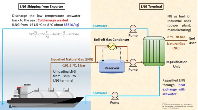
Figure 1-1 Demonstration of the conventional LNG regasification process.
In order to make the transportation abroad more convenient, NG is liquefied to LNG by cooling it to its condensation temperature (-161.5 oC) at atmospheric pressure. The benefits of shipping LNG instead of NG not only helps increase the transportation capacity but also avoid the danger of transiting the flammable materials over a long distance [3]. Unlike the method for short distance transportation, such as pipeline network, which is usually used for inland transportation of NG, the energy cost and the transportation cost are much higher for oversea transportation due to the enormous consumption of energy during the liquefaction process [4]. After arriving in the receiving terminal, LNG has to be sent to the regasification unit for the purpose of vaporizing into NG before it is being used as fuel. Conventionally, seawater is used as the heating source in the regasification unit to vaporize LNG, and after that, the seawater with low temperature is discharged back to the sea. The conventional LNG regasification process is demonstrated in Figure 1-1. In this process, the cold energy with 855 kJ is carried by seawater from LNG to the sea when 1 kg of LNG is being regasified and NG temperature changes from -161.5 oC to 8 oC. In other words, there is a considerable amount of energy loss during this process. Besides, discharging the seawater with low temperature to the sea directly may cause some environmental impacts, especially to the marine life.
1.2 Utilization of LNG Cold Energy
Regarding to the statements above, recuperating the LNG cold energy and applying it in the other aspects is an environmental-friendly strategy to maximize the utilization of imported energy. Figure 1-2 shows some of the well-known applications of the recuperated LNG cold energy, where the utilization of cold energy is categorized into two main applications, and they are called direct application and integrated application [5].
Direct application is a common method that takes the advantage of LNG physical properties. For instance, part of the NG will be vaporized from LNG during the transportation or in the LNG tank, therefore the reliquefaction process is then carried out to prevent the gas loss.
Figure 1-2 Utilization of liquefied natural gas cold energy [5].
In this process, some of the LNG is used as coolant for the recondenser of LNG boil- off gas before sent into the regasification unit [6]. There is another example for direct application proposed by Le et al. (2018) which is a power plant using LNG as working fluid, and it generates electricity while the regasified NG passes through the gas turbine [7]. It is worth to mention that the working fluid is pressurized by using a pump instead of a compressor with high power consumption. Accordingly, the energy efficiency of this power plant is higher than the conventional one. The other direct application is used as the cool energy source for the air conditioning system of the industry nearby the LNG terminal [8].
On other hand, the integrated application is an implicit approach when utilizing the LNG cold energy. For example, the seawater freezing desalination system can use an organic refrigerant to transfer the cold energy from LNG to the ice generator, and then the freshwater ice is produced [9]. Besides, the integrated application can also be applied in the power generation system [10]. In the system proposed by Zhang et al. (2010), the system uses CO2 as working fluid to exploit the cold energy from LNG, and that helps liquefy the CO2 before being sent into the pump, which is only able to increase the pressure of liquid state substance [11]. After that, the pressurized CO2 is vaporized and passes through the turbine to generate electricity. Both of the integrated applications that uses an intermediate substance and delivers the cold energy to the systems result in a better performance and lower cost. There are also the other integrated applications such as the cryogenic air separation [12], cold chain logistic [13], cryogenic pulverization of the plastics and waste [14] and other low temperature utilizations. In conclusion, both the direct application and integrated application intend to maximize the efficiency of energy usage and at the same time function harmoniously with the other system.
1.3 General Principle of Power Generation
Generally speaking, a majority of the power plants use coal as primary energy source to generate electricity on account of its cheaper cost. As a result, people can acquire electricity with a cheaper price to carry out their daily works. However, the excessive reliance on coal in the power generation system leads to serious air pollution which not only affects people’s daily live but also endangers their health [15]. In fact, even in the production procedures or the carbon emission after combustion, the properties of NG fulfill a desirable eco-friendly performance. Hence, NG is an alternative energy source for power generation.
Figure 1-3 The importation of LNG in 2018 [1].
dependence on LNG in power plant. 2019 LNG report mentioned that Taiwan imported about 17.1 Mt in 2018, which is the fifth of the largest importer in the world as shown in Figure 1-3. Among all the imported LNG, about 80% of LNG is used for power generation.
Figure 1-4 The energy efficiency of power systems in Taiwan from 2010 to 2019 [16].
Nonetheless, the steam turbine power plant is usually with low thermal efficiency, which is also known as energy efficiency. The energy efficiency is defined as the net power output (Wnet) per unit of thermal energy carried by the fuel and their relationship is listed in the equations from Equation (1-1) to Equation (1-2). The thermal energy carried by the fuel is calculated in the denominator of Equation (1-2). The lower heating value (LHV) in Equation (1-2) is the released energy when 1 kg of the fuel is burned and the combustion product are the steam and CO2. Higher energy efficiency represents lower energy loss during the energy conversion process. Refer to Figure 1-4 that illustrated by Taiwan Power Company, the average energy efficiency of the steam turbine power plant
is about 40.6% in 2018, which means there is approximately 60% of energy loss in the system [16]. Thus, in order to achieve green technology, the enhancement of energy efficiency that avoids wasting energy becomes a vitally important issue. That is to say, implementation of high energy efficiency power plant is also a solution for the increment of residential electricity demand in the near future [17]. Noted that the energy efficiency of gas turbine power plant is generally lower than steam turbine because the gas compressor is installed in the system.
Wnet = Generated electricity − power consumptions (1-1) ηe = Wnet
LHV×ṁfuel (1-2)
Owing to the fact that energy efficiency is not high enough, a combine cycle power plant was invented, which is also called cogeneration power plant. The cogeneration power plant is a power generation system that integrates both gas turbine system and steam turbine system to achieve high energy efficiency. In the cogeneration power plant, the primary energy, usually the NG, is introduced into the combustor as burning materials.
In order to provide the oxygen to the combustion, the compressed air is mixed with the burning NG in the combustor. In a meantime, the air absorbs the heat energy for the purpose of increasing the temperature and enlarging the enthalpy difference between the inlet and outlet streams of gas turbine. Due to the fact that the air is directly mixed with the burning NG, the outlet stream of the combustor contains the air and the combustion products after the combustion. The mixed stream is also known as flue gas. After that, the high pressure flue gas stream passes through the gas turbine for the gas expansion. The
gas expansion process drives the blades of the turbine and the generator converts the kinetic energy to the electrical energy.
The turbine outlet stream is then introduced to the heat exchanger as a heat source.
Meanwhile, the recirculating water is pressurized and sent to the heat exchanger and absorbs the heat from the flue gas while the exhausted flue gas is purged. It should be pointed out that there is a multistage pressurization and vaporization process of the recirculating water carried out in the heat exchanger and the pumps. The multistage operations not only increase the efficiency of heat exchange but also allow the cogeneration power plant produce the superheated steam with different grades, and they are the low pressure, medium pressure and high pressure steams. If there is no other utilization, the steams are sent to the steam turbine for another power generation.
Afterwards, the outlet stream of steam turbine is cooled and condensed and it is sent back to the recirculating water. In brief, due to the fact that recuperation of heat energy from flue gas reduces the energy loss and that the steam turbine produces extra electricity, they have enhanced the superiority of the cogeneration system if compared with the steam turbine power plant. Besides, the Taiwan Power Company reported that the energy efficiency of cogeneration power plant in 2018 was practically 52%, and this result proves the dominance of the cogeneration system [16].
1.4 COOLCEP-C System
With a focus on the high energy efficiency power plant, cogeneration power plant is not the only choice. The CO2-capturing oxy-fuel power plant with LNG coldness energy utilization (COOLCEP) proposed by Zhang et al. (2010) shows a remarkable energy efficiency that reaches 51.11% and the block diagram of the COOLCEP-C system is illustrated in Figure 1-5. If compared with the oxy-fuel power plant, Dillon et al.(2005) reported that the energy efficiency of natural gas combined cycle (NGCC) oxy-fuel combustion power plant with carbon capture is only 44.7% [18]. It should be emphasized that the energy efficiency of COOLCEP-C system in 2010 was also higher than that of steam and cogeneration power plant mentioned above, whose energy efficiency is 39.4%
and 50.0% (in 2010) respectively. Although the energy efficiency of COOLCEP-C system is not higher than the cogeneration power plant in 2018, the process design of COOLCEP- C system is still a promising concept in the aspect of developing power plant. The COOLCEP-C system integrated both power generation cycle and LNG regasification cycle to form a high energy efficiency system [19].
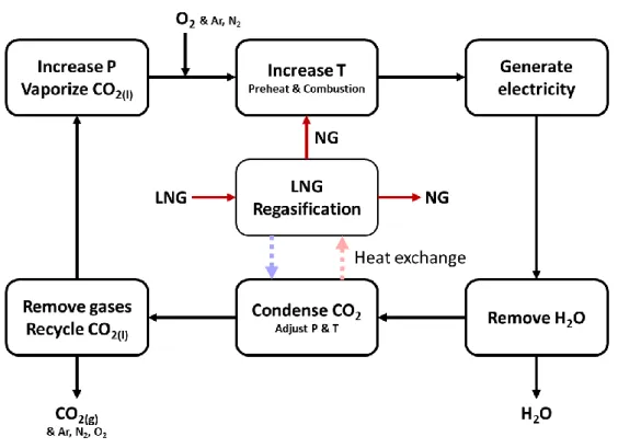
CO2 is used as working fluid to drive the gas turbines and expand to the atmospheric pressure in order to generate electricity. The CO2 is used because of its superiority performance in its thermophysical properties such as the good heat transfer performance and a relatively small expansion ratio if compared to other refrigerant [20]. During the regasification process, LNG acts as refrigerant to liquefy CO2 before CO2 is being pressurized by the pump. According to the phase diagram in Figure 1-6, the CO2 can be liquefied at the conditions of -50oC and 7 bar [21]. The excess CO2 can also be captured in this phase. On the other hand, a considerable amount of cold energy can be supplied to
other systems during the evaporation of pressurized CO2, where the temperature changes from -50 oC to 8 oC. A detailed simulation of the COOLCEP-C plant can be found in Figure 1-7.
Figure 1-5 The block diagram of COOLCEP-C system.
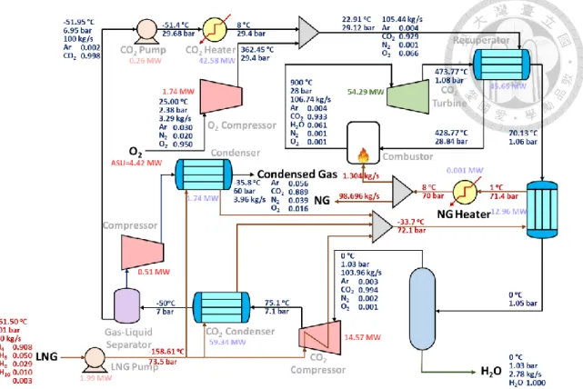
Distinct from conventional gas turbine power plant, COOLCEP-C system shown in Figure 1-7 operates with a Rankine cycle instead of Brayton cycle to increase energy efficiency. Brayton cycle is normally a basic framework of a gas turbine power plant without involving phase change and it consists at least four components that are the compressor, heater, turbine and cooler [22]. In contrast to Brayton cycle, Rankine cycle involves the phase change that usually uses an organic solvent as working fluid, and the fundamental components include the pump, heater, turbine and condenser. The apparent differences are the phase change of Rankine cycle, which required more cold energy to
liquefy the working fluid [23]. But the substitution of the pump for compressor has substantially decreased the power demand of the system.
Figure 1-6 The phase diagram of carbon dioxide [24].
Since the COOLCEP-C system involves the cryogenic LNG stream, it helps reduce the cost of cold energy, and the temperature of LNG is low enough to liquefy CO2. Therefore, the combination of Rankine cycle power system and LNG regasification cycle not only increases the energy efficiency but also provides a comfortable condition to achieve the CO2 capture. In short, the COOLCEP-C (in Figure 1-7) is a multifunctional system that is able to generate electricity, supply cold energy, capture CO2 and regasify liquefied natural gas (LNG).
Figure 1-7 The simulation result of the COOLCEP-C when the CO2 Pump outlet pressure is 29.68 bar and the TIT is 900 oC.
This research aims to maximize the application of LNG cold energy and develop a low carbon emission power plant with high energy efficiency. Refer to Figure 1-3, Japan is the largest LNG importation country in the world. Accordingly, Jera company listed the maximum power output and the maximum design energy efficiency of the cogeneration power plant in Japan in Table 1-1. Among of them, Nishi-Nagoya thermal power station has the highest energy efficiency, which is about 62.3 %. This power station operates the gas turbine at 1600 oC and produces nearly 2,376 MW electricity and the data is collected in March 2018 [25]. In the progression of power plant, this result should be set as a benchmark to be achieved and the design concept of COOLCEP-C system is almost parallel with the objectives in this research. However, the energy efficiency of COOLCEP-C system is relatively lower than the present power plant. In order to develop
an implementable power plant, some modifications are carried out based on the COOLCEP-C system. Lastly, the sensitivity analysis is executed for the purpose of optimization.
Table 1-1 The performance of the cogeneration power plant in Japan [26].
Thermal Power Station
Maximum power output (MW)
Highest design energy efficiency (%)
Nishi-Nagoya 2,376 62.3
Kawasaki 3,420 60.8
Futtsu 5,160 58.6
Joetsu 2,380 58.5
Shin-Nagoya 3,058 58
Chiba 4,380 57.7
Kashima 5,660 57.2
Yokohama 3,541 55.8
Shinagawa 1,140 55.3
Kawagoe 4,800 53.9
Chita Daini 1,708 44.1
Chita 3,966 42.5
Chapter 2 Conceptual Design and Assumptions
2.1 Physical Properties and Assumptions
A commercial plant-wide simulation software- AspenPlus is used in the system to carry out the simulation and sensitivity analysis. The Predictive Soave-Redlich-Kwong (PSRK) equation of state is used as the thermodynamic model in the simulation, and it can imitate the behavior of the polar and non-polar compound mixtures even in high temperatures and pressures [27]. Before executing the simulations, the important parameters and assumptions that are consistent with those in the research of Zhang et al.
(2010) have been applied and they are listed in below.
1. The basis of the simulation for the systems are set at 100 kg/s of recirculating CO2
and 100 kg/s of LNG in order to make a fair comparison between different systems, and it is also a more intuitive basis to estimate the scale-up scheme.
2. The pressure drop is assumed 1-3% of the inlet stream, and the actual value is consistent with Zhang et al. (2010) which is depending on the operation unit.
3. The combustion reaction in the combustor is assumed to be a complete combustion, that is, the combustion product is only water and carbon dioxide, and the excess ratio for the O2 is 2% higher than its required stoichiometric ratio.
4. The gas turbine is assumed to be an irreversible turbine that the isentropic efficiency is 90% and the mechanical efficiency is 96%.
5. The temperature limitation for the gas turbine is neglected in this research.
6. The minimum temperature difference of recuperator and the reheat procedure are set at 45oC, and the minimum temperature difference of CO2 condenser, which is also the LNG vaporization unit is set at 8 oC.
7. The efficiency of the compressor and the pump are 88% and 80% respectively.
8. The components of LNG feed stream are the CH4, C2H6, C3H8, C4H10 and N2, whose molar composition are the 90.82 mol%, 4.97 mol%, 2.93 mol%, 1.01 mol% and 0.27 mol% respectively, and its lower heating value (LHV) is 49,200 kJ/kg.
9. The initial conditions of the LNG inlet stream are -161.5 oC and 1.013 bar.
10. The components of O2 feed stream are the O2, Ar and N2, whose molar compositions are 95 mol%, 3 mol% and 2 mol%.
11. The initial conditions of the O2 inlet stream are 25 oC and 2.38 bar, and the power consumption for producing O2 in Air Separation Unit (ASU) is 812 kJ/kg.
2.2 System Modification
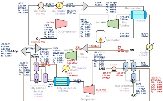
A modified system is proposed in this research based on the modifications of the COOLCEP-C system. This Modified COOLCEP-C system (MCOOLCEP-C) consists of the power generation cycle and the LNG regasification cycle as shown in Figure 2-1. The integration of the both cycles has achieved mutual benefits that has decreased the energy cost and led the system to enviromental-friendly operations. In this research, the MCOOLCEP-C system is introduced first and then the strategy of modifications based on COOLCEP-C system (in Figure 1-7) is discussed in the following.
Figure 2-1 The simulation result of the MCOOLCEP-C when the CO2 Pump outlet pressure is 29.68 bar and the TIT is 900 oC.
To begin with, the power generation cycle of the MCOOLCEP-C system is presented.
In this cycle, recirculating CO2 stream is fixed at 100 kg/s, which is the basis of the system.
The CO2 stream in liquid state is pressurized by the pump and it is then vaporized by
flowing through a vaporizer. It is important to note that the vaporization process can supply a considerable amount of cold energy to the other system if the recuperation process for the cold energy is carried out. After that, the vaporized CO2 stream is mixed with the pressurized O2 stream and the mixed stream is preheated by the Recuperator. The O2 stream comes from the air separation unit (ASU) that is able to supply oxygen with high concentration. Conventionally, the air will be introduced to the combustor for the purpose of providing O2 to the combustion reaction. However, the utilization of air leads to introduce about 79% of inert gas such as N2, Ar and the other gases to the system, and the gases will also circulate in the system. Accordingly, the circulation of inert gas in the system results in the increment of energy cost for some equipments in particular the compressor and condenser. It is also making the equipments cost become higher due to the increment of the circulating flowrates. Hence, instead of using the air, the application of O2 stream is one of the strategies that increases the energy efficiency and reduces the load of CO2 capture.
Next, the preheated mixed stream is sent to the Combustor. In the Combustor, the mixed stream combines with the burning NG (fuel) and the evident increment of the temperature results in the enlargment of the enthalpy difference between the inlet and outlet streams of gas turbine significantly. The mixed stream with the combustion products, which are the steam and carbon dioxide, is then sent to the gas turbine (GT). It is noteworthy that the stream experiences the pressurization and the enlargment of the enthalpy difference between the inlet and outlet streams of gas turbine leads to enhance the produced kinetic energy during the volume expansion in turbine. At the same time, the generator that connected to the turbine converts the kinetic energy to electrical energy.
its temperature decreases to 40 oC in the following cooler. In the Recuperator, the excess heat energy is recovered and the recovered heat energy is used in the previous preheat step.
Thereafter, the gas stream with 40 oC is introduced to the H2O separator and the H2O separator utilizes the cryogenic LNG as cold energy source to separate water from the gas stream. Meanwhile, the separated water is discharged from the bottom of the separator while the desired gas stream flows out from the top. The cooling source for the cooler equipped before the H2O separator can be the seawater or the cooling water that is cheap in price. So that, the installation of cooler not only reduces the required cold energy of H2O separator but also operates in a nearly zero operating cost. Additionally, a little amount of CO2 dissolves in water and this is one of the facts that causes the CO2 loss from the system during discharging the water from H2O separator. For the purpose of separating the gases other than the CO2, the gas stream is pressurized to the condensation pressure of CO2 by the gas compressor and condensed by the heat exchange with the cryogenic LNG in the CO2 condenser. Noted that the temperature of the stream is dramtically increased after the compression and the increment of the temperature provides sufficient energy for the regasification of LNG. Then, the stream with partial vapor is sent to the CO2 capture section. In the CO2 capture section, the vapor phase stream is firstly separated from the inlet stream, and CO2 is still the main component in the separated vapor stream. Therefore, the CO2 capture section removes the impurities such as N2, Ar and the excess O2 from the vapor stream and maintains the concentration of CO2 in the outlet stream at a desired standard. Meanwhile, the CO2 in the liquid state from the gas-liquid separator (the first column in the CO2 capture section) is recycled back to the system in a fixed amount of 100 kg/s while the excessive liquid state CO
(split stream) joins with the outlet stream from the third column (CHX3) of the CO2
capture section to be the CO2 capture stream.
For the LNG cycle, the input LNG is pumped to 150 bar and sent to the H2O separator and CO2 capture section for the purpose of absorbing the released heat. In order to condense the CO2 in the outlet stream of CO2 compressor, LNG is then sent to the CO2
condenser and the LNG is regasified to NG when it absorbs the heat energy from the mixed gas stream. After that, the NG is heated as NG passes through the NG Heater. The NG Heater increases the enthalpy difference between the inlet and outlet streams of gas turbine of NG by increasing its temperature, and this step is similar to the function of the combustor. It should be pointed out that hot water is suggested to be used as the heat source of NG Heater instead of low pressure steam. Since the temperature difference between the inlet and outlet streams of NG heater is quite small, it is not necessary to use the low pressure steam that is relatively expensive in price. Subsequently, the outlet stream is sent to the NG Turbine and makes the volume expansion happen for another power generation. Next, the NG stream is splitted into a fuel stream for the entire system while the other is prepared to be transported to the end-users. Noted that the temperature and pressure of the NG stream before leaving the system are fixed at 8 oC and 70 bar for the purpose of transportation.
2.2.1 H
2O Separator
Since the framework of the MCOOLCEP-C system is quite similar to the COOLCEP-C system, it is important to elaborate that due to some of the drawbacks in the COOLCEP-C system. Some modifications are done in this research to form another
system called the MCOOLCEP-C system. The detailed description of the modifications is listed below.
Figure 2-2 The configuration of the proposed H2O Separator [28].
First of all, the assumption that water can be perfectly separated in the H2O separator does not correspond to the reality. Thus, it is suggested that the original H2O Separator can be replaced by three heat exchangers [28], which are HX1, HX2 and HX3 and the proposed H2O separator is illustrated in Figure 2-2. In order to condense the water vapor in the gas stream, the HX1 decreases the temperature of the gas stream and removes the condensed water from the gas stream. Then, the gas stream is sent from HX1 to HX2, and the separated water is sent to HX3. The HX2 is known as the freeze-drying column that can further remove the water in the gas stream [29]. Meanwhile, the dehydrated gas stream is sent to the compressor and the ice removed from the gas stream in HX2 is also
sent to the HX3. The temperature of dehydrated gas stream is very low when compared to that of the COOLCEP-C system. The low temperature stream allows the compressor to compress the stream to the desired pressure with a lower power consumption, and this is due to the principle of thermal contraction. Furthermore, HX3 is a CO2 recovered column that retrieves the CO2 trapped in the ice [30] or dissolved in the water by increasing the temperature. Although the retrieved amount of CO2 is quite small, all of them will flow through the CO2 capture stream. In other words, the HX3 of the H2O separator can increase the capture ratio of the system. However, there is still a little amount of the CO2 loss that happens along with the discharging of H2O stream from HX3.
The heat released by HX1 and HX2 is absorbed by the pressurized LNG, and the heat source of the HX3 is seawater. On the other hand, since the temperature of the gas stream is low enough, the cooling system that follows the compressor is then removed. Originally, LNG supplies cold energy to the cooling system of the compressor. But with the modification in this research, it turns to be the fact that LNG supplies cold energy to the condenser of the H2O separator. Therefore, the proposed H2O separator is more practical and the extra energy source is no more needed.
2.2.2 CO
2Capture Section
Secondly, since there are some drawbacks in the CO2 Capture section, some modifications are applied to the MCOOLCEP-C system. In this section, the condensed CO2 is sent to a gas liquid separator for the purpose of discharging the non-condensable gas. After discharging, the liquefied CO2 is recycled back to the system. But in fact, there is still some CO2 remaining in the non-condensable gas stream, so in order to retrieve the CO2 from it, the non-condensable gas stream is then compressed and condensed. After
CO2 can be obtained. Admittedly, this CO2 capture method is able to capture all of the CO2 produced in the combustion reaction. In other words, the CO2 recovery reaches 100%.
However, since the usage of the compressor and condenser consumes great amount of energy, it is recognized as an energy-intensive method. Besides, in order to remove the impurities in the condensed gas stream such as Ar, N2 and O2 and to obtain CO2 stream with higher purity, the condensed gas stream requires a further processing after being compressed and condensed.
Figure 2-3 The configuration of the proposed CO2 Capture section.
As shown in Figure 2-3, the modification of the CO2 Capture section done in this research is to substitute two heat exchangers, which are CHX2 and CHX3, to the compressor and condenser following the gas-liquid separator. The vapor stream from the gas-liquid separator is sent to CHX2. The CHX2 with extremely low temperature is also known as a dry ice maker [31], so that the impurities in gas phase can be easily removed.
Subsequently, the separated CO (dry ice) is sent to the CHX3. The CHX3 with higher
temperature melts the CO2(s) to liquid state and this procedure can further purify the outlet CO2(l) stream by removing the trapped impurities in CO2(s). The outlet stream of CO2
Capture section joins then with the excessive liquid state CO2 from the splitter of the recycle stream, and the joined stream is named as the Captured CO2 stream. At the same time, the impurities are directly purged from the CHX2 of CO2 Capture section. Besides, the heat released by the CHX2 is also absorbed by the pressurized LNG, and the seawater is used as the heat source of the CHX3. Therefore, the proposed CO2 Capture section can also operate without needing extra energy source. If compared with the COOLCEP-C system, the concentration of the Captured CO2 stream in the MCOOLCEP-C system is increased to 99.94 mol%. The Captured CO2 with such high purity can be utilized in most of the process [32] such as direct use [33], mineral carbonation, fuel production [34] and the chemical production [35]. However, the CO2 recovery, which is also known as CO2
capture ratio, is decreased to 98.60%. The decrement of the CO2 recovery is caused by the CO2 loss during the purge of the H2O in the H2O separator and CO2 capture section.
Hence, CO2 Capture section in MCOOLCEP-C system is more energy-saving and it can capture CO2 with higher purity.
2.2.3 Power Generation in LNG Regasification Cycle
Moreover, the modification of LNG regasification cycle is also applied in the system.
Refer to Le et al. (2018), the LNG regasification cycle has the potential to generate extra electricity by using natural gas (NG) to drive the additional gas turbine (GT) after the regasification process. In this research, the inlet pressure of LNG increases to 150 bar by the pump, and this helps NG drive the turbine after the vaporization. In order to maintain the conditions of the NG at 70 bar and 8oC before being sent to the end-user, an additional
On the other hand, LNG is now used as the cold energy source for the condenser of the H2O separator and the CO2 condenser. After the modification, the required amount of LNG is remained at 100 kg/s. It should be noted that the required amount of LNG is a conservative mass flowrate of LNG that carries a sufficient cold energy that tolerate to an appropriate adjustment of operating conditions. In other words, the required amount of LNG is neither the minimum demand of LNG cold energy to the system nor the maximum amount for the regasification of LNG.
In summary, the modifications include the H2O separator, CO2 Capture section, distribution of LNG cold energy and an additional NG turbine for the pressurized NG. In contrast to the COOLCEP-C system, the MCOOLCEP-C system not only improves the purity of captured CO2 and the amount of generated electricity but also decreases the energy consumption.
2.3 Proposed Systems
In order to further improve the MCOOLCEP-C system, Reheated MCOOLCEP-C (RMCOOLCEP-C) system is also proposed in this research, and the simulation result with base conditions is illustrated in Figure 2-4. In the RMCOOLCEP-C system, the gas turbine outlet stream flows through the combustor along the pipeline to absorb heat energy, so that the enthalpy difference between the inlet and outlet streams of gas turbine of the stream is enhanced. After that, the reheated stream is then introduced into the gas turbine to generate more electricity. Consequently, the equipment cost of the recuperator is foreseeable to be higher due to the larger requirement of the heat transfer area.
Nevertheless, the RMCOOLCEP-C system is still having a potential to be a profitable system due to the extra power generation. Apart from the combustor, gas turbines section and recuperator, the operating conditions of the other apparatus are almost the same with the basis of 100 kg/s of recirculating CO2.
Figure 2-4 The simulation result of the RMCOOLCEP-C when the CO2 Pump outlet pressure is 29.68 bar and the TIT is 900 oC.
On the other hand, Zhang et al. (2010) also discussed the COOLCEP-S system with a basis of 101.61 kg/s recirculating CO2 proposed by Deng et al. (2004) [36]. The COOLCEP-S system is claimed to be a system with high energy efficiency whose expansion pressure of CO2 in turbine is only the condensation pressure. In this situation, it does not require a further compression in the latter process. In other words, the compressor that follows the H2O separator is removed from the system. Due to the removal of the compressor which reduces its energy and equipment cost, the COOLCEP- S system has high energy efficiency and lower investment cost. But the studied results done by Zhang et al. (2010) shows that COOLCEP-S system requires more working fluid to produce 20 MW of electricity when compared with COOLCEP-C. This result implies that COOLCEP-S produces lower amount of electricity when using the same mass
flowrate of recirculating CO2 and required LNG as COOLCEP-C. Unfortunately, this result is unable to give an impartial judgement to the system, especially in the aspect of the total annual cost (TAC) because the increment of recirculating working fluid might result in higher investment cost for the system.
In order to provide a fair assessment between the both systems in the aspect of system performance such as net power output, CO2 recovery or the TAC, the simulation of COOLCEP-S system integrated with the modifications, which is Modified COOLCEP- S (MCOOLCEP-S) system mentioned above is showed in Figure 2-5. Apart from these modifications, there are also some further modifications needed to be done. In fact, the compression of gas leads to a significant increment of outlet stream temperature. Thus, due to lack of heat energy, the elimination of the compressor makes LNG inefficient to gasify in the CO2 condenser. To solve this problem, a heater is added before CO2
condenser to make sure the gas stream has sufficient energy to regasify LNG. Besides, heat integration can be also applied to the system by integrating the additional heater and the cooler before the H2O separator. After these modifications, the MCOOLCEP-S system can now operate under the basis of 100 kg/s of recirculating CO2 with 100 kg/s of required LNG.
Additionally, Figure 2-6 shows that the simulation result of the Reheated COOLCEP-S (RMCOOLCEP-S) system, which is a system that is equipped with an additional reheated step and an extra gas turbine, and it is also taken into investigation in the following research.
Figure 2-5 The simulation result of the MCOOLCEP-S when the CO2 Pump outlet pressure is 29.68 bar and the TIT is 900 oC.
Figure 2-6 The simulation result of the RMCOOLCEP-S when the CO2 Pump outlet pressure is 29.68 bar and the TIT is 900 oC.
Chapter 3 Results and Discussions
3.1 Consideration of Pump Consumption
Basis of 100 kg/s recirculating CO2 is using in the simulation of Zhang et al. (2010).
Neglected the pump consumption, CO2 turbine power output of COOLCEP-C system is about 33.05 MW and its energy efficiency reaches 51.51% when the pressurized CO2 is 29.68 bar and the Combustor temperature is 900 oC. To improve the COOLCEP-C system, a hypothesis is then made which is the higher the pressure of pressurized CO2, the higher the energy efficiency. Therefore, the negligible assumption to the pump is not applicable, since pump consumptions will be higher as the CO2 operating pressure increases. If the pump consumption is considered, CO2 turbine power output of COOLCEP-C system is about 32.79 MW and its energy efficiency is only 51.11% when the pressurized CO2 is 29.68 bar and the Combustor temperature is 900 oC.
Table 3-1 Comparison of simulation results with and without including the pump.
According to Table 3-1., the differences of energy efficiency between the results with
predicted to be more significant after adjusting the related parameter. Hence, to include pump consumptions in the following analysis not only gives a more precise result, it also makes this system able to be compared with the other Brayton cycle system under the same circumstance.
After modifying the original system, the MCOOLCEP-C system is predicted to be able to achieve the optimized conditions by adjusting some important variables. In order to obtain the optimized variables, the sensitivity analysis is then carried out. But before that, two hypotheses are made for the optimization. The first hypothesis is that the higher the CO2 Pump outlet pressure, the higher the efficiency. The other hypothesis is that the higher the Combustor temperature (or turbine inlet temperature, TIT), the higher the efficiency. Actually, the gas turbine is not capable of withstanding such an extremely high inlet temperature such as 2000 oC due to the limitation of the heat-resisting materials and the cooling technologies in gas turbine [37]. Additionally, the Mitsubishi Heavy Industries reported that the gas turbine that is able to operate at 1700 oC is still under development in 2008 [38]. However, the progression in technology goes rapidly nowadays and the Nishi-Nagoya power station operated its TIT at 1600 oC in 2018 and pointed out that the heat resistance of apparatus has been improved. It is believed that the heat resistance issue about the apparatus will be resolved in the coming years. Therefore, the limitation of apparatus is not the main consideration in this research.
3.2 Sensitivity Analysis for H
2O Separator
Figure 3-1 The effect of HX1 temperature to total required cooling duty of the H2O separator.
Figure 3-2 The effect of HX2 temperature to total required cooling duty of the H2O separator, duty and the energy efficiency of the system.
Figure 3-3 The effect of HX3 temperature to total required cooling duty of the H2O separator, the CO2 loss in the gas stream during dehydration.
In order to understand how the temperature of the HX1, HX2 and HX3 in the H2O separator will affect the system, sensitivity analysis is first conducted in this research, and the result is shown in the Figures from Figure 3-1 to Figure 3-3. In the H2O separator, the feed at 40oC enters HX1 for the purpose of removing the condensed water from the gas stream, so that the analysis of the HX1 temperature changed from 40oC to -40oC. As shown in Figure 3-1, the total required cooling duty of the H2O separator is the lowest, when HX1 temperature is 1oC. But when HX1 temperature is changed, CO2 loss in the gas stream during dehydration and the concentration of H2O in the gas stream to CO2
compressor (the output stream of the H2O separator) remain unchanged. This is due to the fact that the lower the HX1 temperature, the smaller the cooling duty of the HX2. And when HX1 temperature is 0oC, water phase change occurs, releasing large amount of energy and increasing cooling duty. So the total required cooling duty of the H2O separator is the lowest at 1oC.
Next, the gas stream at 1oC is sent to HX2 and the principle of freezing-drying is used to separate the water from the gas. As shown in Figure 3-2, when HX2 temperature is adjusted from -78oC to -74oC, the total required cooling duty of the H2O separator decreases from 17.18 MW to 16.86 MW, the power consumption of the CO2 Compressor increases from 10.56 MW to 10.77 MW, and the energy efficiency of the MCOOLCEP- C system decreases from 58.14% to 57.81%. However, it doesn’t cause any effect on the CO2 loss in the gas stream during dehydration, when HX2 temperature is changed. Since the energy efficiency stands in the middle of this research, -78oC is selected as the temperature of the gas stream to CO2 compressor under the circumstance of sufficient LNG (cold energy) exists in the system. And at this temperature, the power consumption of the CO2 Compressor is the lowest, and the energy efficiency is the highest. The reason why the temperature cannot be lower adjusted is that -78.5oC is the sublimation point of CO2. If under -78.5oC, the gas phase CO2 will be transformed into dry ice.
The feed of the HX3 is the H2O that is removed from HX1 and HX2. The function of HX3 is to increase the temperature for the purpose of retrieving the CO2 that is trapped or dissolved in H2O. Meanwhile, water is discharged from the system after the CO2 has been retrieved. As shown in Figure 3-3, the HX3 temperature is increased from 0oC to 90oC, leading to the result that the total required cooling duty of the H2O separator increases exponentially. However, CO2 loss in the gas stream during dehydration decreases. In other words, the higher the temperature, the higher the CO2 recovery at the cost of more cooling and heating duty. Since the change of the total required cooling duty of the H2O separator at the range of 0oC to 30oC is not obvious, 20oC is selected in order not to impose any extra heating duty on the system. Besides, HX3 can use seawater at
not only decrease the water in the gas to 1 ppm but also increase the energy efficiency of the system to 58.14%.
3.3 Sensitivity Analysis for CO
2Capture Section
Figure 3-4 The effect of CO2 Condenser temperature to CO2 capture purity, capture ratio and mass flowrate of the split stream.
Figure 3-5 The effect of CHX2 temperature to total required cooling duty of the H2O separator, compressor duty and the energy efficiency of the system.
Figure 3-6 The effect of CHX3 temperature to total required cooling duty of the H2O separator the CO2 loss in the gas stream during dehydration.
Furthermore, the sensitivity analysis for the CO2 Capture section is carried out, and the effect of the CO2 Condenser temperature, CHX2 temperature and CHX3 temperature to the CO2 Capture ratio and capture purity are illustrated in the Figures from Figure 3-4 to Figure 3-6. Since the first column in the CO2 capture section is just a gas-liquid separator (C1), there is no significant effect to system. Therefore, the effect of CO2
Condenser temperature is investigated. Figure 3-4 shows that when the temperature of the CO2 Condenser decreases from -50oC to -53oC, the capture ratio is increased from 99.04% to 99.14%, the capture purity is decreased from 99.94% to 99.84% and the mass flowrate of the split stream is increased from 0.25 kg/s to 2.07 kg/s. The higher the heat released of CO2, the higher the ratio of CO2 liquefied in the CO2 Condenser, and it is leading to the fact that the lower the CO2 Condenser temperature, the higher the mass flowrate of the split stream. The Captured CO2 stream is a stream that mixed with the outlet stream of the CHX3 (purified stream) and the excessive liquid state CO2 from the
splitter of the recycle stream (split stream). So that, the capture ratio is increased if the CO2 Condenser temperature become lower. And owing to the fact that the purity of the purified stream is always higher than that in the split stream, the increment of the flowrate of the split stream is leading to decrease the capture purity.
CHX2 is the impurities removal that will also transform the CO2 into the solid form (dry ice) with a cryogenic temperature. The CHX2 temperature has no effect to the capture purity but it has an evident influence to the capture ratio, and this result can be found in Figure 3-5. The capture ratio can be increased by decreasing the operating temperature in CHX2, and -87oC has been chosen in the following simulations. When the CHX2 operates at -87oC, the capture ratio can reach a standard that >98.5%, and the LNG cold energy is always sufficient for all the operations. On the other hand, the capture purity is maintained by the CHX3. Theoretically, some of the impurities will be entrapped within the dry ice during cryogenic freezing [30]. Therefore, the function of the CHX3 is to melt the dry ice and release the impurities that entrapped within the dry ice or dissolved in the liquefied CO2. The simulation result in Figure 3-6 shows that the higher the CHX3 temperature, the higher the capture purity, and it is consistent with the solubility properties of gas in liquid.
3.4 MCOOLCEP-C System
Besides, NG turbine is located in the LNG regasification cycle. Since the parameter adjustment imposes no effect on the power output of the NG turbine, it would be a fixed value at 3.52 MW in all the system except the COOLCEP-C system. At the same time, power generation of the NG turbine does not use NG as fuel, thus, the power output of the NG turbine will not be discussed below. In other words, the net power output only discusses the power output of CO2 turbine and power consumption in the power generation cycle. Since the adjustment of the parameters will affect the net power output of the power generation cycle, the total net power output of the system is not the net power output itself but the net power output of CO2 turbine plus power output of NG turbine.
With 100 kg/s recirculating system, the base condition for the MCOOLCEP-C system is consistent with the COOLCEP-C system in the aspect of CO2 Pump outlet pressure set at 29.68 bar and the TIT set at 900 oC. Based on these parameters, the CO2
turbine produces about 37.31 MW and the energy efficiency achieves 58.14 %. The energy efficiency has the significant increment because of the lower energy consumption of the CO2 compressor that follows the H2O separator. The decrement of energy consumption for the CO2 compressor is owning to the fact that the inlet temperature of its inlet stream decreases considerably. Due to the thermal contraction principle, the decrement in temperature leads to the result that the volume of the inlet stream of compressor has a smaller the volume. In fact, compression of the stream with smaller volume to a fixed pressure consumes lesser energy if compared with the stream with larger volume. Therefore, the energy consumption for the compressor is lowered in the MCOOLCEP-C system and this leads to an obvious increment in energy efficiency. On
the other hand, the CO2 recovery of the MCOOLCEP-C system is reduced to 98.60%, and this is due to the fact that after the modifications, the CO2 loss happens along with the discharging of H2O and non-condensable gas. In order to understand the effect of the variables to the MCOOLCEP-C system, the sensitivity analysis of each variable is then carried out. The step size for the pressure is set at 2 bar and for the TIT is set at 100 oC.
3.4.1 Sensitivity Analysis for CO
2Pump Outlet Pressure
Figure 3-7 The effect of CO2 Pump outlet pressure to the MCOOLCEP-C system when TIT is fixed at 900 oC (left), and demonstrations of the effect to the MCOOLCEP-C
system as the CO2 Pump outlet pressure increased from 32 bar to 36 bar (right).
In order to understand the effect of the CO2 Pump outlet pressure to the MCOOLCEP-C system, the result of sensitivity analysis is illustrated in Figure 3-7 is the demonstration results when the CO2 Pump outlet pressure increases from 32 bar to 36 bar.
During this analysis, the combustor temperature is fixed at 900 oC. The orange line in the Figure 3-7(left) shows the net power output of CO2 turbine while the purple line shows the required amount of the fuel. Besides, the bar chart represents the energy efficiency, and the energy efficiency is directly proportional to the ratio of the orange and the purple
![Figure 1-2 Utilization of liquefied natural gas cold energy [5].](https://thumb-ap.123doks.com/thumbv2/9libinfo/9599223.628606/16.892.129.689.637.1043/figure-utilization-liquefied-natural-gas-cold-energy.webp)
![Figure 1-3 The importation of LNG in 2018 [1].](https://thumb-ap.123doks.com/thumbv2/9libinfo/9599223.628606/18.892.159.739.561.1014/figure-importation-lng.webp)
![Figure 1-4 The energy efficiency of power systems in Taiwan from 2010 to 2019 [16].](https://thumb-ap.123doks.com/thumbv2/9libinfo/9599223.628606/19.892.131.766.301.677/figure-energy-efficiency-power-systems-taiwan.webp)
![Figure 1-6 The phase diagram of carbon dioxide [24].](https://thumb-ap.123doks.com/thumbv2/9libinfo/9599223.628606/24.892.178.783.124.730/figure-phase-diagram-carbon-dioxide.webp)
![Table 1-1 The performance of the cogeneration power plant in Japan [26].](https://thumb-ap.123doks.com/thumbv2/9libinfo/9599223.628606/26.892.157.760.336.912/table-performance-cogeneration-power-plant-japan.webp)
![Figure 2-2 The configuration of the proposed H 2 O Separator [28].](https://thumb-ap.123doks.com/thumbv2/9libinfo/9599223.628606/33.892.145.740.230.678/figure-configuration-proposed-h-o-separator.webp)
