Structures and Properties of AlTiON Coatings
Synthesized by Cathodic Arc Deposition Process
Wei-Yu Ho
Hsu-Hung Hsueh
Da-Yung Wang
Woei-Yun Ho
Abstract
To further improve wear resistance of AlTiN coatings for dry cutting
applications, the development of AlTiON coatings by cathodic arc deposition was investigated. The AlTiON coatings in combination of AlTiN/CrN multilayered coating were investigated with using Al0.67Ti0.33 and Cr targets at various O2and
N2gas ratios in this study. The structure of the various AlTiON coatings as surface
layers was explored using scanning electron microscopy, x-ray diffraction (XRD), and x-ray photoelectron spectroscopy. The XRD analyses showed that the AlTiON films had NaCl-type structure which is similar to the AlTiN film. The effect of
oxygen content on the AlTiON films results in increased hardness and roughness with respect to the AlTiN as the oxygen flow increase. Wear tests show that the AlTiON specimen deposited at the highest oxygen flow exhibits a lower coefficient of friction and wear rate compared to that of the AlTiN film. For the coating with higher amount of oxygen, the hardness and oxide phase may play a major role to improve the wear behavior in this study. Compared to AlTiN, the corrosion resistance of the AlTiON coated specimen is significantly improved by incorporating hisher oxygen content into the coating. The thermal test reveals the best oxidation resistance for the AlTiON specimen with the highest oxygen content. The AlTiON coating with the best
properties was performed at an oxygen flows of 30 sccm while the nitrogen flow kept at 320 sccm.
Keywords: AlTiON, Cathodic Arc Deposition, TGA
Wei-Yu Ho:Associate Professor, Depart ment of Materials science and engineerin g, MingDao Universit y
Hsu-Hung Hsu eh:Graduate Student, Department of Materials science and engin eering, MingDao Universit y
Da-Yung Wang:Professor, Department of Materials science and engineering, MingDao Universit y
I. Introduction
The fundamental advantage of AlTiN coating is the presence of a dense, highly adhesive, protective oxide film at its surface, preventing deterioration of the coating material. The low thermal conductivity of this coating is another advantage for machining applications. These properties enable correspondingly higher cutting speeds to be selected, since thermal loading of the substrate is lower [1-9]. However, AlTiN coating, in general, shows poorer performance than TiN in the case of the abrasive wear resistance. The friction coefficient of TiAlN films higher than that of TiN films was attributed to the brittle fracture of coating layer during sliding. [3]. Further improvement of the hardness, thermal stability, chemical inertness, corrosion resistance, etc. of the AlTiN coatings was recently studied. An increasing number of hard coatings for engineering applications is to use coatings in multilayer or
composite structures that combine the properties of dual coating materials [10-15]. On the other hand, post treatment of the AlTiN coatings was also developed to improve the wear resistance. Katahira et al [4] presented the results of electrolytic in-process dressing (ELID) grinding experiments performed on TiAlN film and characterization of the tribological characteristics of the produced films. They suggest that ELID grinding formed an oxide layer in the machined surface of TiAlN film. Therefore, ELID-ground TiAlN film exhibits superior tribological properties by virtue of not only the highly smooth surface, but also formation of an oxide layer. Annealing of nano-crystalline AlTiN coating has been performed in vacuum at 700 and 900 °C during 2 h. This post treatment leads to some structure transformations that affect coating properties and the tool life improvements [16].
To our knowledge, study on (Ti, Al)ON coatings by introducing oxygen in TiAlN have been carried out. However, Kawata et al [17] studied TiAlCN and TiAlON multilayer films produced by PECVD. They concluded that the
TiAlON/TiAlN/TiN multilayer films exhibited the better corrosion resistance than TiAlN/TiN coating. In dry drilling of tempered steel the wear mechanisms of
oxygen-rich TiAlON-coated WC-carbide tools were investigated [18]. It showed that TiAlON films have a superior wear resistance than TiAlN films in dry drilling of tempered steel due to improved oxidation resistance of TiAlON coatings. The
addition of oxygen enables the TiAlON coatings with better ductility, which improves the cutting performances [19].
II. Experimental
Specimens were made of JIS SKH51 steel (0.92% C, 0.28%Mn, 3.64% Cr, 0.26% Co, 1.94% V, 5.79% W, 5.04 % Mo, Fe balanced), JIS SUS304 (18 ~ 20% Cr, 8 ~ 10 % Ni, Fe balanced), and WC- 8% Co, respectively. The samples for wear tests were machined into a diameter of 30mm and thickness of 5 mm. Prior to PVD treatment, the samples were ultrasonically cleaned in acetone and alcohol and then fixed in the chamber holder. To ensure the well adhesion of the AlTiON layers, the first CrN layer and the second (Al,Ti)N/CrN multilayer are used a supporting layer. Therefore, a CAD system with dual arc sources was used to deposit various
multi-layered coatings in a single process. The Al0.67Ti0.33AlTi and Cr target materials
(purity 99.9%) were vertically opposed mounted on the chamber wall, respectively. The top layer of AlTiN and various TiAlON layers are obtained by introducing the various N2+ O2mixture gases into the chamber as reactive gases to form various
films. The bias voltage during deposition was kept at –150V. Details of the deposition process parameters are listed in Table 1.
Crystallographic characteristics of the as-deposited specimens were analysed by X-ray diffraction (XRD;modelPAN analyticalX’pertPRD (MRD))with Cu Kα radiation. TheCu Kα lineat0.15405 nm wasused asthesourcefordiffraction pattern analysis. Scanning electron microscopy (SEM; model JOEL JSM-5600) was carried out to observe the fractured cross-section and surface morphology of the various coatings. Surface profile was used to scan and measure the roughness of the coatings. X-ray photoemission spectroscopy (XPS) measurements were performed using a VG ESCALAB 250 electron spectrometer with a monochromatic Al Kα (1486.6eV) source. The spectra were collected at a take-off angle of 90° with pass energy of 20 eV. All of the tested samples were etched for 30 seconds before the measurement. Hardness of films was measured using a nanoindenter (Hysitron Triboindenter) under the applied load of 5 mN. The penetrative depth of the indented tip was approximately 50 nm. Tribological tests were performed on a ball-on-disc tribometer (CSEM). The total sliding distance of the ball on the tested samples was set at 2000 m. The tests were conducted with no lubricant along a circular track of 20 mm diameter against a 6.0 mm diameter WC ball at 0.3 m/s under a normal load of 10 N in ambient atmosphere (RH = 65%). The wear loss was analyzed from the
cross-sectional area of the wear track, as measured by the surface profilometer (XP-1, America Ambios Inc.). The dc potentiodynamic tests were conducted in 1M H2SO4
solution through a three-electrode cell connected to a Potentiostat/Galvanostat (Model 263A) system. A saturated calomel electrode (SCE) was used as a reference to
was determined with the sweeping setting rate at 1mV/s and sweeping potential range from –0.7V to 0.8V. After each potentiodynamic polarization test, the corrosion potential, Ecorr, and the corrosion current density, Icorr, can be determined by Tafel plot.
The thermal analysis was tested in air using thermogravimetric analyzer (TGA) and differential scanning calorimerty (DSC) (Mettler Toledo TGA/SDAT851). About 8 mg samples were placed in an alumina sample holder and heated at 10 K/min from ambient to 1100oC in open air. The percent of weight gain with respect to the original weight of samples was corrected.
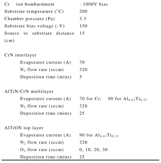
Table 1 Details of the deposition parameters of coating processes
C r i o n b o mb a r d me n t - 1 0 0 0 V b i a s S u b s t r a t e t e mp e r a t u r e (oC ) 2 0 0 C h a mb e r p r e s s u r e ( P a ) 3 . 3 S u b s t r a t e b i a s v o l t a g e ( - V ) 1 5 0 S o u r c e t o s u b s t r a t e d i s t a n c e ( c m) 1 5 C r N i n t e r l a ye r E v a p o r a t o r c u r r en t ( A) 7 0 N2 fl o w r a t e ( s c c m) 3 2 0 D e p o s i t i o n t i me ( mi n s ) 5 Al T i N / C r N mu l t i l a ye r E v a p o r a t o r c u r r en t ( A) 7 0 fo r C r ; 9 0 fo r Al0 . 6 7T i0 . 3 3 N2 fl o w r a t e ( s c c m) 3 2 0 D e p o s i t i o n t i me ( mi n s ) 2 5 Al T i O N t o p l a ye r E v a p o r a t o r c u r r en t ( A) 9 0 fo r Al0 . 6 7T i0 . 3 3 N2 fl o w r a t e ( s c c m) 3 2 0 O2 fl o w r a t e ( s c c m) 0 , 1 0 , 2 0 , 3 0 D e p o s i t i o n t i me ( mi n s ) 2 5
III. Results and Discussion
1. Film structure analysis
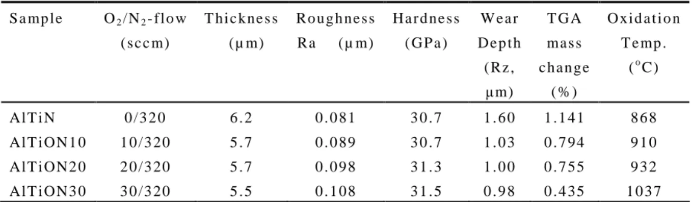
of three different layers that, from the substrate, the first layer is CrN used as adhesive layer, and the second layer is (Al,Ti)N/CrN multilayer acted as supporting layer. The AlTiN and various TiAlON layers are deposited as the top layer. The adhesion of these different layers is well bonded indicating the possibility of the continuing deposition process. Table 2 lists the thickness, roughness and hardness properties of the various coatings for comparison. The total thickness of all of the studied coatings is up to 5.5 ~ 6.2 µm. From the SEM images, the thickness of these coatings is slightly decreased from 6.2 of AlTiN to 5.5 μmof AlTiON30 with the highest oxygen flow. The hardness determined by nano-indentation test show the slightly increase as the oxygen flow increase. The higher hardness value of TiAlON compared to that of AlTiN is owing to the oxygen content resulting in solid solution strengthening or crystalline oxide phases in the coatings.
Table 2 The properties of the various coatings with respect to the various oxygen flow S a mp l e O2/ N2- fl o w ( s c c m) T h i c k n e s s ( µ m) R o u g h n e s s R a ( µ m) H a r d n e s s ( G P a ) W e a r D e p t h ( R z , μm) T G A ma s s c h a n g e ( % ) O x i d a t i o n T e mp . (oC ) Al T i N 0 / 3 2 0 6 . 2 0 . 0 8 1 3 0 . 7 1 . 6 0 1 . 1 4 1 8 6 8 Al T i O N 1 0 1 0 / 3 2 0 5 . 7 0 . 0 8 9 3 0 . 7 1 . 0 3 0 . 7 9 4 9 1 0 Al T i O N 2 0 2 0 / 3 2 0 5 . 7 0 . 0 9 8 3 1 . 3 1 . 0 0 0 . 7 5 5 9 3 2 Al T i O N 3 0 3 0 / 3 2 0 5 . 5 0 . 1 0 8 3 1 . 5 0 . 9 8 0 . 4 3 5 1 0 3 7
Fig. 2 shows the surface morphology of the coatings deposited with an oxygen flow varied from 0 to 30 sccm while the nitrogen flow kept at 320 sccm. From the result, all of the as-deposited films in this study exhibit similar images, showing some porosities and droplets in the submicro-, micro- and macro- scales which are
non-uniformly distributed on the coating surface. It is well known that droplets from the arc source are generally the major cause of surface roughness in arc deposited coatings. From the SEM images, the surface roughness of AlTiON films is essentially smoother than that of AlTiN films. Sjölén et al [19] revealed that the introduction of reactive O2/N2mixture gas from the zero to 0.3 into the process chamber causes the
target poisoning effect by forming oxide compounds on the surface of the targets. The poisoned cathode can induce the decrease of the larger number of macroparticles emitted from the arc spot. However, by introducing the lower O2/N2mixture gas up to
Fig. 2. SEM photographs of the surface morphology for the various coatings. (a) AlTiN, (b)AlTiON10, (c)AlTiON20, (d)AlTiON30.
Typical XRD diffraction patterns from AlTiN and AlTiON films are shown in Fig. 3. The total thickness of all of the studied coatings is up to 5.5 ~ 6.2 µm which means the XRD diffractions results from the coatings themselves. The AlTiN film was polycrystalline exhibiting similar diffraction peaksrelated to cubicδ-TiN phase. The diffraction peaks of (111), (200), (220), and (311) orientation could be identified. Apparently, XRD shows the diffraction peaks of AlTiON coatings with different oxygen contents consistent to that of AlTiN. In Fig. 3, the preferred orientation of (111) is dominated in the AlTiN coating. After addition of oxygen in AlTiN coating, the intensity of (200), (220) increase with respected to the increase of oxygen flow, indicating the polycrystalline structure in the AlTiON coating. There are no peaks indexed as crystalline oxide phases observed in the coatings as the amount of oxygen is increased. 20 40 60 80 100 AlTiON 30 AlTiON 20 AlTiON 10 AlTiN (3 1 1 ) (2 2 0 ) (2 0 0 ) (1 1 1 ) in te n s it y (a rb .u .) 2 Theta (degree)
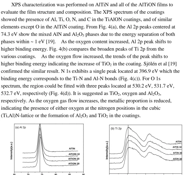
XPS characterization was performed on AlTiN and all of the AlTiON films to evaluate the film structure and composition. The XPS spectrum of the coatings showed the presence of Al, Ti, O, N, and C in the TiAlON coatings, and of similar elements except O in the AlTiN coating. From Fig. 4(a), the Al 2p peaks centered at 74.3 eV show the mixed AlN and Al2O3phases due to the energy separation of both
phases within ~ 1 eV [19]. As the oxygen content increased, Al 2p peak shifts to higher binding energy. Fig. 4(b) compares the broaden peaks of Ti 2p from the various coatings. As the oxygen flow increased, the trends of the peak shifts to higher binding energy indicating the increase of TiO2in the coating. Sjölén et al [19]
confirmed the similar result. N 1s exhibits a single peak located at 396.9 eV which the binding energy corresponds to the Ti-N and Al-N bonds (Fig. 4(c)). For O 1s
spectrum, the region could be fitted with three peaks located at 530.2 eV, 531.7 eV, 532.7 eV, respectively (Fig. 4(d)). It is suggested as TiO2, oxygen and Al2O3,
respectively. As the oxygen gas flow increases, the metallic proportion is reduced, indicating the presence of either oxygen at the nitrogen positions in the cubic (Ti,Al)N-lattice or the formation of Al2O3and TiO2in the coatings.
65 70 75 80 85 90 (a) Al 2p AlTiON 30 AlTiON 20 AlTiON 10 AlTiN In te n s it y (a .u .) Binding Energy(eV) 450 455 460 465 470 (b) Ti 2p AlTiN 30 AlTiN 20 AlTiN 10 AlTiN In te n s it y (a .u .) Bingind Energy(ev) 390 395 400 405 410 (c) N 1s AlTiN AlTiON 30 AlTiON 20 AlTiON 10 Binding Energy(eV) In te n s it y (a .u .) 525 530 535 540 545 (d) O 1s AlTiON 30 AlTiON 20 AlTiON 10 In te n s it y (a .u .) Binding Energy(eV)
Chemical composition of the various coatings measured by XPS was shown in Fig. 5. The Al/Ti-ratios are essentially constant for all of the coatings even the oxygen gas increases. The fraction of the oxygen and nitrogen composition of the various coatings by XPS showed obviously increase of oxygen but a slight decrease of nitrogen as the O2gas supply increases from 0 to 30 sccm, as shown in Fig.5. The
results show that cubic (Al,Ti)N thin films deposited by arc deposition process incorporate oxygen up to 13.6 at.% which in exchange for nitrogen without changing its crystallographic structure.
0 10 20 30 0 10 20 30 40 50 60
O
Ti
N
Al
C o n c e n tr a ti o n (a t. % ) Oxygen flow (sccm)Fig. 5. Composition profiles of the Al, Ti, N, O of the various coatings with respect to the oxygen flows.
2. Tribological resistance
A ball-on-disk tribometer was used to evaluate the friction coefficient of the various coatings against a WC-Co ball. Fig. 6 shows the coefficient of friction versus sliding distance for all of the specimens under a load of 10 N. Up to a sliding distance of 250 m, all of the tested coatings show a rapidly increasing coefficient of friction against a WC-Co ball. For the AlTiN coating, a steady-state friction coefficient remains in the range of 0.70 ~ 0.80 until the end of the test. A lower friction coefficient of AlTiON layers compared to that of AlTiN layer is observed. In
also the lower friction coefficient and better wear resistance during the sliding against WC-Co ball. 0 500 1000 1500 2000 0.3 0.4 0.5 0.6 0.7 0.8 0.9 TiAlON 30 TiAlON 10 TiAlON 20 TiAlN C o ef fi ci en t o f F ri ct io n (u ) Travel Distance (m)
Fig. 6. The friction coefficients for specimens coated with AlTiN and various AlTiON films. The ball-on-disc test was carried out against WC-Co ball under a load of 10 N without lubricant.
3. Corrosion resistance
Potentiodynamic polarization curves for various coatings deposited on JIS SUS 304 stainless steels measured in 1M H2SO4solution are presented in Fig. 7. The
polarization curves of potential (relative to SCE) vs. current density of specimens were obtained by sweeping the potential from -0.7V up to an anodic potential of 0.80V with a scan rate of 1 mV/s. As shown in Fig. 7, all of the specimens exhibited a typical active corrosive behavior and then turned to passive behavior until the end of test. The measured data of the corrosion test are listed in Table 3 for comparison. The comparison between the corrosion potential (Ecorr) of coated specimens revealed that
the increase of Ecorrfrom -0.203 V of the AlTiN-coated specimens to 0.084 V of the
AlTiON30 which was depsoited at the oxygen flow of 30 sccm. The increase of Ecorr
represented a nobler electrode potential being achieved - indicating the improvement of corrosion resistance on stainless steel with hard coatings. In this study, the increase of Ecorrof specimens is due to the increase of oxygen contents in the coatings,
resulting in the formation of oxide phases blocking corrosion channel of the coatings. Examination of the current density of coated specimens showed a significant reduction of current density as the coatings possessed higher oxygen content. The AlTiN-coated specimen corroded far more quickly than all of the coated specimens. The lowest current density (Icorr= 0.161 µA/cm2) was observed for the AlTiON30
oxide phase in the coating blocking direct path between a corrosive environment and the substrate. -9 -8 -7 -6 -5 -4 -0.6 -0.4 -0.2 0.0 0.2 0.4 0.6 0.8 AlTiON10 AlTiN AlTiON20 AlTiON30 P o te n ti a l (V )
Current Density(logI, A/cm2)
Fig. 7. Potentiodynamic polarization curves for the AlTiN- and various AlTiON-coated specimens in 1M H2SO4solution.
Table 3. Comparison of the corrosion behavior of the AlTiN- and various AlTiON-coated specimens in 1M H2SO4solution. S a mp l e O2/ N2- fl o w ( s c c m) C o r r o s i o n v o l t a g e ( V ) C o r r o s i o n c u r r e n t d e n s i t y ( µ A/ c m2) Al T i N 0 / 3 2 0 -0 . 2 0 3 0 . 7 7 5 Al T i O N 1 0 1 0 / 3 2 0 -0 . 0 5 4 0 . 3 2 2 Al T i O N 2 0 2 0 / 3 2 0 -0 . 0 3 6 0 . 2 0 8 Al T i O N 3 0 3 0 / 3 2 0 0 . 0 8 4 0 . 1 6 1
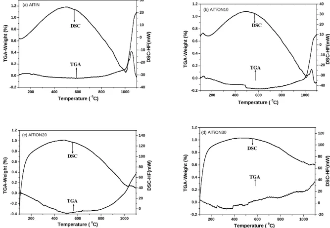
4. Thermal behaviours
established that oxidation of AlTiN proceeds by outward diffusion of Al to form Al-rich oxide at the topmost surface and inward diffusion of O to form Ti-rich oxide at the interface to TiAlN [20, 21]. The presence of excess oxygen causing the
formation of Al2O3and TiO2in the coating may play a decisive role in reducing
oxidation rates for AlTiON coatings.
200 400 600 800 1000 -0.2 0.0 0.2 0.4 0.6 0.8 1.0 1.2 Temperature (0C) T G A -W e ig h t (% ) -40 -30 -20 -10 0 10 20 30 (a) AlTiN DSC TGA D S C -H F (m W ) 200 400 600 800 1000 -0.2 0.0 0.2 0.4 0.6 0.8 1.0 1.2 Temperature (0C) T G A -W e ig h t (% ) -40 -30 -20 -10 0 10 20 30 40 (b) AlTiON10 TGA DSC D S C -H F (m W ) 200 400 600 800 1000 -0.4 -0.2 0.0 0.2 0.4 0.6 0.8 1.0 1.2 (c) AlTiON20 Temperature (0C) T G A -W e ig h t (% ) 0 20 40 60 80 100 120 140 TGA DSC D S C -H F (m W ) 200 400 600 800 1000 -0.2 0.0 0.2 0.4 0.6 0.8 1.0 1.2 (d) AlTiON30 T G A -W e ig h t (% ) Temperature (0C) -20 0 20 40 60 80 100 120 TGA DSC D S C -H F (m W )
Fig. 8. TGA/DSC measurement of the oxidation of the various coatings in air. Heating rate 10oC/min.
IV. Conclusions
The arc-evaporated AlTiON coatings comprise of three different layers that, from the substrate, the first is CrN used as adhesive layer, and the second is (Al,Ti)N/CrN multilayer acted as supporting layer. The top layer of AlTiN and various TiAlON layers were deposited following the (Al,Ti)N/CrN multilayer. The results show that cubic AlTiN thin films deposited by arc deposition process
incorporate oxygen up to 13 at.% which in exchange for nitrogen without changing its crystallographic structure. The addition of oxygen content in the AlTiN coatings slightly increased thecoatings’hardnesscompared to AlTiN.Thesurfaceroughness of AlTiON films is increased due to the addition of oxygen as a reactive gas to cause the subsequent target poisoning. Wear tests show that the AlTiON30 specimen deposited at the highest oxygen flow exhibits a lower coefficient of friction compared to that of the AlTiN film. For the coating with higher amount of oxygen, the hardness and oxide phase may play a major role to improve the wear behavior in this study. Compared to AlTiN, the corrosion resistance of the AlTiON30 specimen is
significantly improved by incorporating the highest oxygen content into the coating. The TGA test reveals the best oxidation resistance for the AlTiON30 specimen. The presence of oxygen in the coating appears to form oxides in the coating.
Acknowledgements
The authors would like to thank the financial support from the National Science Council of Taiwan under project contract NSC 96-2221-E-451-005.
References
1. Y. Wang, Surf. Coat. Technol., 94-95 (1997) 60-63.
2. S.K. Wu, H.C. Lin, P.L. Liu, Surface and Coatings Technology 124 (2000) 97–103. 3. Seog-Young Yoon, Kwang O Lee, Sung Soo Kang, Kwang Ho Kim, Journal of
Materials Processing Technology 130–131 (2002) 260–26.
4. K. Katahira, Y. Watanabe, H. Ohmori, T. Kato, International Journal of Machine Tools & Manufacture, 42 (2002) 1307–1313.
5. S. PalDey, S.C. Deevi, Materials Science and Engineering, A342 (2003) 58 -79. 6. Mirjam Arndt, Thorsten Kacsich, Surface and Coatings Technology 163 –164
(2003) 674 - 680.
8. Wenji Zhao, Fanghua Mei, Yunshan Dong, Geyang Li, Journal of Materials Processing Technology 176 (2006) 179 -182.
9. Yin-Yu Chang, Da-Yung Wang, Surface & Coatings Technology 201 (2007) 6699 - 6701.
10. J.H. Hsieh, C. Liang, C.H. Yu, W. Wu, Surface and Coatings Technology 108–109 (1998) 132–137
11. V. Derflinger, H. Brändle, H. Zimmermann, Surf. Coat. Technol., 113 (1999) 286–292.
12. K. Katahira, Y. Watanabe, H. Ohmori, T. Kato, International Journal of Machine Tools & Manufacture 42 (2002) 1307–1313
13. H. Meidia, A.G. Cullis, C. Schönjahn, W.D. Münz, J.M. Rodenburg, Surface and Coatings Technology 151 –152 (2002) 209–213.
14. N.J.M. Carvalho, E. Zoestbergen, B.J. Kooi, J.Th.M. De Hosson, Thin Solid Films 429 (2003) 179–189.
15. Chi-Lung Chang, Jui-Yun Jao, Wei-Yu Ho, Da-Yung Wang, Vacuum 81 (2007) 604- 609.
16. G.S. Fox-Rabinovich, J.L. Endrino, B.D. Beake, A.I. Kovalev, S.C. Veldhuis, L. Ning, F. Fontaine, A. Gray, Surf. Coat. Technol., 202 (2008) 2985.
17. K. Kawata, H. Sugimura, O. Takai, Thin Solid Films 390 (2001) 64-69.
18. K. Tönshoff, B. Karpuschewski, A. Mohlfeld, T. Leyendecker, G. Erkens, H.G. Fuß, R. Wenke, Surf. Coat. Technol., 108–109 (1998) 535–542.
19. J. Sjölén, L. Karlsson, S. Braun, R. Murdey, A. Hörling, L. Hultman, Surf. Coat. Technol., 201 (2007) 6392–6403.
20. S.G. Harris, E.D. Doyle, Y.-C. Wong, P.R. Munroe, J.M. Cairney, J.M. Long, Surf. Coat. Technol., 183 (2004) 283–294.