行政院國家科學委員會補助專題研究計畫 ■成 果 報 告
□期中進度報告
第四代無線通訊之合作暨認知網路技術--
子計畫三:支援第四代系統群播與廣播服務之互助網路技術
計畫類別:□ 個別型計畫 ■ 整合型計畫 計畫編號:NSC 97-2219-E-011-007
執行期間: 97 年 8 月 1 日至 97 年 7 月 31 日
計畫主持人:鄭瑞光 共同主持人:
計畫參與人員:黃國瑞、劉達瑞、高周業、鄭文研、張愽立、Quang Vu Nguyen 成果報告類型(依經費核定清單規定繳交):□精簡報告 ■完整報告
本成果報告包括以下應繳交之附件:
□赴國外出差或研習心得報告一份
□赴大陸地區出差或研習心得報告一份
■出席國際學術會議心得報告及發表之論文各一份
□國際合作研究計畫國外研究報告書一份
處理方式:除產學合作研究計畫、提升產業技術及人才培育研究計畫、列管計畫 及下列情形者外,得立即公開查詢
□涉及專利或其他智慧財產權,□一年■二年後可公開查詢 執行單位:台灣科技大學電子系
中 華 民 國 97 年 8 月 4 日
可供推廣之研發成果資料表
■可申請專利 □ 可技術移轉 日期: 年 月 日
國科會補助計畫
計畫名稱:第四代無線通訊之合作暨認知網路技術--子計畫三:支援 第四代系統群播與廣播服務之互助網路技術
計畫主持人:鄭瑞光
計畫編號:97-2219-E-011-007- 學門領域:電信
技術/創作名稱 廣播與群播服務之服務品質回報機制
發明人/創作人 鄭瑞光
技術說明
中文:
廣播與群撥服務必須無區別的讓 Awake 模式及 Idle 模式 下的用戶收看,過往的設計中,廣播與群撥服務並不提供上 行之品質回報通道,因此,大大降低了傳送廣播與群撥服務 的頻譜使用效率。根據相關文獻可知,若提供上行之品質回 報機制,將可讓網路端有效的調整傳送廣播與群撥服務之實 體層相關參數,以提昇頻譜使用效率。本發明提供了一個低 訊令複雜度的品質回報機制,應用此方法,將可提供廣播與 群撥服務無線資源管理所需的資訊,以提昇網路的頻譜使用 效率。
附件二
英文:
Normally, multicast and broadcast services (MBS) is offered in the downlink only and the MBS service flows should be transmitted and maintained for SS either in awake/sleep mode or in idle mode. However, It has been shown in the literature that the number of synchronized transmitting cellsin an MBS zone,thecellsize,and theusers’location distribution are factors that may affect the selection of MCS state.
Unfortunately, the network cannot dynamically allocate the radio resource for BSs belonging to the same MBS zone due to the lack of a feedback mechanism. In order to enhance the spectral efficiency of E-MBS, we propose a feedback mechanism with low signaling overhead for both awake and idle SSs receiving the same MBS services to report their service qualities.
可利用之產業 及 可開發之產品
行動通訊產業
技術特點
低信令複雜度
推廣及運用的價值
※ 1.每項研發成果請填寫一式二份,一份隨成果報告送繳本會,一份送 貴單位研發成果推
廣單位(如技術移轉中心)。
※ 2.本項研發成果若尚未申請專利,請勿揭露可申請專利之主要內容。
※ 3.本表若不敷使用,請自行影印使用。
Part I: 廣播與群播服務之服務品質回報機制
一、背景、動機和目的
It was found in the literature that PtM in downlink would be a common approach for MBS. In this approach, the modulation and channel coding scheme (MCS) is normally adjusted based on the worst-case user. Hence, exact value of CQI for each user may not be necessary to be reported via the feedback channel. The network only need to know ‘Is there any user whose CQI (RSSI/BER/QoS) cannotbeguaranteed?’Hence,a“Yes/No”strollpollfeedback should begood enough forthispurpose. Hence, we proposed a threshold-based channel quality feedback method.
At the BS side, it uses multicast-Poll (MC-Poll) to query the downlink signal quality and reserves shared or dedicated uplink resource (for users belonging to the same multicast group) as reply channel.
The query conditions can be CQI (RSSI/BER/QoS) thresholds or regions. UEs shall send a message via the reply channel if its CQI is less than the given CQI-threshold or its CQI belongs to the specified region.
The uplink transmission power may be set to a given value or based open loop power control. At the BS side, BS may decrease theMCS orincreasethetransmission powerto improvetheUE’sCQIifany reply is received. Optionally, BS may send the MC-ACK to UEs for confirmation. If no reply is received, BS may increase the CQI threshold for the next query and may increase the MCS or decrease the transmission power to improve spectral efficiency.
In 3GPP R2-063503, RAN2 asks RAN1 to provide information on the (relative) efficiency of 5 radio configurations (when referring to a single cell) for transmitting multicast and broadcast services (MBS). RAN1 adds a new configuration and provides simulation results for the 6 configurations, which includes
T1: Normal PTP Radio Bearer (i.e.,CQI is known)
T2 : MBSFN (MBS single frequency network) with soft combining
T3: Single cell PTM
No Interference Co-ordination of neighbour cells
No closed-loop PC and ARQ support
T4: Single cell PTM
UE providing Uplink ACK/NACK feedback
T5: Single cell PTM
Interference reduction by not transmitting on neighbour cells
T6: Single cell PTM (added by RAN1)
UE providing Uplink CQI and ACK/NACK feedback
Simulations were conduct to evaluate the effectiveness of the six methods and the results were summarized in 3GPP R1-072637. Both uniform and non-uniform user distributions were considered. The user densities ranging from 0.1 to 4.0 mean users per cell were simulated. They assumed that T1 and T6 adopt the same per-user CQI reporting feedback mechanism in terms of the rate and type of CQI feedback, utilize the same transport block re-transmission and combining strategy, and the feedback is error-free. For T6, they further assumed that ACK/NACK feedback was configured using ACK/NACK channelswhereNACK indication attheeNB wasthelogical“OR”oftheper-user NACK indications.
MIMO was not applied to either T1 or T6. Some concerns were raised regarding the interference generated by common uplink feedback.
They found that T1 (PtP+CQI) and T6 (PtM+CQI) achieves an identical performance if the user density is around 1 user/cell. T2 (MBSFN with soft combining) outperformed both T1 and T6 if the user density falls between 2 to 4 users/cell. T6 (PtM+CQI) is better if the user density is between 1 to 2 users/cell. They concluded that, if T1 and T2 are adopted, T3 would need to be considered as it offers advantages over other techniques in single cell scenarios with high user densities. In addition, the downlink radio efficiency of T3 is realised by T6 (with feedback turned off) if T6 and T2 are adopted.
Although RAN1 noted that widespread commercial deployment of MBS service in LTE would likely be accompanied by the use of MBSFN methods (T2), RAN1 did identify asynchronous networks as an instance where T2 would be inapplicable. In this case, T6 would likely outperform T1 over a significant range of user spatial densities. Importantly, however, it was also noted that the performance of T6 would converge to that of T3 as the user density increases.
According to their simulation, we know that PtP (T1) has the least spectral efficiency. In contrast,
MBSFN (T2) has the best spectral efficiency resulted from soft combining but could be inapplicable in asynchronous networks. Single Cell PtM (T6) will have a good spectral efficiency if CQI is available, which requires the supporting of uplink signaling channel. If single frequency network (SFN) is not used, the best choice would be Single cell PtM (T6). In T6, UEs have to provide Uplink CQI and ACK/NACK feedback. However, the need of extra signalling messages may result in a degraded network performance.
Hence, it is beneficial to obtain channel information with minimum signaling overhead.
Existing MBS feedback methods have some limitations. First of all, some of them were developed based on PtP communication concept. That is, each UE has to feedback it CQI or ACK/NACK information to the base station. Therefore, the amount of signaling messages will be proportional to the UE density. Second, part of the feedback methods are designed for special purpose and thus, not suitable for MBS services. Normally, the feedback signals from UEs can be utilized by network operators to determine the modulation and coding schemes (MCS) or the network service architecture (i.e., MBSFN or Single cell PtM). Hence, various feedback methods may result in different reporting accuracy and thus, affect the performance of radio resource management. Normally, there is a trade-off between the reporting accuracy and the resulted signaling messages of the feedback method. Therefore, the purpose of the invention is to propose a feedback method that can minimize the required signaling messages under a given reporting accuracy constraint.
二、相關技術略述
Wehavesearched US Patentusing keywordsof‘Multicast+ Wireless’in thefield of‘Title.’There are 18 patents found and three of them are highly related. We also used thekeywordsof‘Multicast+ Cellular’in thefield of‘Title.’and only oneirrelevantpatentwasfound.Therelated patentsarelisted below:
US Patent 7,054,643: System for rate control of multicast data delivery in a wireless network US Patent 6,996,104: Rate allocation and control for multicast services in wireless networks
US Patent 6,633,765: Method and apparatus for performing coverage control for multicast services in a wireless network
US Patents 7,054,643 and 6,996,104 are owned by Nokia. The inventors proposed to use downlink shared channel for MBS. End device has to report its signal quality. US Patent 6,633,765 is owned by Qualcomm. The inventors proposed to use downlink shared channel for MBMS. BS has to initiate membership query for a given multicast group. End device starts an independent, randomly chosen report delay timer. The end device that with the minimum delay shall transmit first and the remaining end devices do not have to respond to the membership query. It reduces the number of responses to membership queries that need to be sent.
In addition to granted patents, we also found are some related 3GPP standard contributions. In 3GPP R2-061985,Motorolaproposed a documententitled as‘MBMS Modulation and Coding State Selection Method’.They proposean MCS determination mechanism forMBMS,which isclosely related to the counting mechanism used in R6 MBMS. A threshold value and a “probability factor” are used to suppress NACK feedback. Before the MBMS service transmission starts, the network indicates an MCS state for the MBMS transmission and each UE has to transmit an NACK message if its radio conditions can’tsupporttheMCS state.In 3GPP R2-061985, a binary MCS search algorithm is proposed. The network has to select a MCS state, and configure the probability factors and SINR thresholds (probability factors are set in increasing order). Each UE has to determine if it should transmit a NACK based on its SINR.UE won’tresponseto thenetwork ifUE’sSINR issmallerthan thegiven SINR threshold. In case thatUE’sSINR isgreaterthatthegiven SINR threshold and can’tsupporttheindicated MCS,theUE has to send an NACK if it passes the probability test. Otherwise, the UE has to wait for next probability iteration. The network will use a less aggressive MCS state if it detects a NACK. In case that the network detects nothing, it will increase the probability factor, and then uses a more aggressive MCS state. If the network does not receive any NACK when the highest probability factor (typically = 1) is used, then it switches to the more aggressive MCS state. In R2-061985, the proposed method is used to determine the MCS state for MBSFN and the SIR Threshold is fixed for a given number of transmitting cells.
Alcatel-Lucent has proposed another contribution with number R2-070180, which is entitled as
‘CQIreporting in E-MBMS singlecelltransmission.’They define methodsforlimituplink signaling load.
This method is used to determine the MCS state for Single Cell. They suggest each UE report its specific CQI range via pilot bits in order to reduce signaling overhead. Hence, the distribution of CQI in each cell can be obtained. However, the drawback of this method is that a pre-determined CQI range is used and thus, it requires extra resource in uplink. In R2-070909, TD-Tech proposed a feedback suppression and rate control method to reduce CQI feedback for RRC_IDLE UEs. In this method, UE in either
RRC_IDLE or RRC_CONNECTED mode is allowed to feedback its CQI for its interested MBMS service. Only RRC_IDLE UE, whose CQI is less than the worst CQI in all RRC_CONNECTED UEs has to feedback their CQI via non-synchronized channel. The base station then selects MCS for MBMS according to the worst CQI in all RRC_CONNECTED and RRC_IDLE UEs.
In R2-070909, an MBMS rate control method is proposed to determine the MCS state for MBSFN based on reported CQIfrom UEs.In thismethod,NodeB may monotonicdecreaseMBMS’datarateif UE feedback CQI is worse than the current worst CQI. Node B attempts to increase MBMS data rate if it receives no CQI feedback in N frames/Scheduling. Node B broadcasts the renewed Worst CQI (MCS) on MICH. UE feedbacks its required CQI if the renewed CQI can not support its QoS requirement. Node B would adjust MBMS data rate according to theUEs’feedback.NodeB could increaseMBMS datarate, and keep this new data rata until UE feedback a worse CQI if no UE feedbacks its CQI.
三、創意構想或技術內容
Normally, multicast and broadcast services (MBS) is offered in the downlink only and the MBS service flows should be transmitted and maintained for SS either in awake/sleep mode or in idle mode. However, It has been shown in the literature that the number of synchronized transmitting cellsin an MBS zone,thecellsize,and theusers’location distribution arefactors that may affect the selection of MCS state. Unfortunately, the network cannot dynamically allocate the radio resource (e.g., transmission power control, MCS state selection, HARQ parameter setting) for BSs belonging to the same MBS zone due to the lack of a feedback mechanism. In order to enhance the spectral efficiency of E-MBS, a feedback mechanism with low signaling overhead is required for both awake and idle SSs that receiving the same MBS services to report their service qualities.
NACK-based Channel Feedback
The selections of proper feedback channel and right feedback information are two main issues that should be considered while designing the feedback mechanism. The feedback channel should be able to accommodate SSs either in awake/sleep mode or in the idle mode. The feedback information should be detail enough for SSs to indicate their received quality and also be simple enough to minimize the uplink signaling overhead.
Possible choices for the feedback channel include a random access channel, a shared uplink control channel, or a dedicate uplink control channel. For SSs in idle mode, they can only use random access channel to communicate with the BS. For SSs in awake/sleep mode, they can use random access channel, shared uplink control channel, or dedicate uplink control channel to communicate with the BS. In order to minimize the uplink signaling overhead for E-MBS, a random access channel that can be shared by SSs in both awake/sleep mode and idle mode is preferred.
There are two options in allocating the uplink feedback channel for MBS. BS can either allocate a single common random access feedback channel or multiple random access feedback
channels. In case that a single common random access feedback channel is used, the same message is sent by SSs/MSs and all of the sent messages are then combined at the BS as multipath effect. In case that multiple random access feedback channels are chosen, SSs/MSs that satisfied the given conditions shall report. In this case, BS may get the CQI distribution, which may be useful for MCS adjustment or power control. The threshold-based channel quality feedback method can eliminate the collision in the uplink shared channel, minimize the uplink signaling message, and do not require extra network synchronization function.
Potential options for the feedback information include ACK/NACK and CQI. The ACK/NACK may be used to indicate that thesatisfaction/dissatisfaction ofSS’QoS requirement(e.g.,SNR,packeterrorrate (PER), peak signal-to-noise ratio (PSNR), etc.). The CQI can be used to carry the exact channel quality (e.g., Physical CINR, Effective CINR feedback, MOMO-related feedback, etc.) experienced by the SS. In MBS, the radio resource is normally adjusted according to poor-quality SSs but not all SSs. Hence, it is preferred to let dissatisfaction SSs use a simple NACK message to report its QoS status. In MBS, the network cares more about the received quality of the reported SS and does not interest in its user identity. Therefore, a CDMA code, instead of a user-specific message, can be used by SSs receiving the same E-MBS service flow to indicate their NACKs to minimize signaling overhead.
In this patent, we propose to
Reserve a group of CDMA ranging code for E-MBS, where each E-MBS-specific CDMA code is assigned to one E-MBS service flow or is shared by multiple E-MBS service flows;
Allocate a common random access channel (or multiple random access feedback channels) for both awake/sleep mode and idle mode SSs that receiving the same E-MBS service flows to report their channel quality. The allocation of the common random access channel can be periodic or
event-triggered, which depends on a feedback condition specified by the network.
SS, who is not satisfied with a given feedback condition (e.g., SNR, PER, PSNR), shall indicate a NACK by sending its CDMA code through the allocated common random access channel.
Note that, the network has to announce the feedback condition and its associated channel allocation in a MBS-specific control channel (or a general broadcasting channel) that can be received by both
awake/sleep mode and idle mode SSs. The same common random access channel can be shared by multiple
E-MBS service flows that use different CDMA codes and thus, minimize the signaling overhead for channel quality feedback.
Joint power control and link adaptation for MBS
A joint power control and link adaptation algorithm is then proposed to increase the bandwidth efficiency of MBS. During the initialization, the network assigns a CDMA code to the given MBS service flow (MBS-SF) during service creation.
Definition of the terms used in the algorithm.
- MCScurrent: the modulation and channel coding currently used to transmit the MBS service, M1
<=MCScurrent<=Mmax, where M1 is the most conservative MCS level.
- Pcurrent: the transmission power currently used to transmit the MBS service.Pmin<= P <=Pmax. - Pnew: the new transmission power to be used to
transmit the MBS service.Pmin<= P <=Pmax. - :the step size for power adjustment
- SNR: the feedback condition
- SNR(Mi): the minimum SNR requirement of MCSMi. Note that SNR(Mi)<SNR(Mmax)
Step 1: Initially,MCScurrent=Mi, Pcurrent= Pnew=Pmax, and SNR= SNR(MCScurrent), where Miis a proper MCS level estimated during initialization.
Step 2: Send a Multicast-Poll (MC-Poll) message in the downlink and monitor the specified feedback channel. If any NACK is received and Pcurrent= Pnew, go to Step 3 (i.e., increase the transmission power or decrease the MCS level). If any NACK is received and Pcurrent<> Pnew, go to Step 4 (do not adjust the transmission power). If no NACK is received, go to Step 5 (i.e., decrease the transmission power or increase the MCS level).
Step 3: If Pcurrent< Pmax, go to Step 3.1 (increase the transmission power). If Pcurrent= Pmax, go to Step 3.2 (decrease the MCS level).
Step 3.1: Set Pcurrent= Pcurrent+ . Use the updated transmission power to transmit MBS content.
Go to Step 2.
Step 3.2: If MCScurrent> Mi, set MCScurrent= MCScurrent–1. Otherwise, set MCScurrent= M1. Use the updated MCS to transmit MBS content and update SNR=SNR(MCScurrent). Go to Step 2.
Step 4: Set Pnew= Pcurrentand SNR=SNR(MCScurrent) (keep the current transmission power). Go to Step 2.
Step 5: If Pcurrent= Pnew(new transmission power is not adjusted), go to Step 5.1. If Pcurrent<> Pnew(new transmission power is negatively adjusted but no NACK is received), go to Step 5.2.
Step 5.1: Set Pnew= Pcurrent- and SNR=SNR(MCScurrent+ ) (i.e., adjust the new transmission power and announce the feedback information). Go to Step 2.
Step 5.2: If (Pmax- Pnew) >= (SNR(MCScurrent+1) - SNR(MCScurrent)) (i.e., power margin is good enough to accommodate an MCS adjustment), go to Step 5.2.1. If (Pmax- Pnew) < (SNR(MCScurrent
+1) - SNR(MCScurrent)) (i.e., power margin is not good enough to accommodate an MCS adjustment), go to Step 5.2.2.
Step 5.2.1: Set MCScurrent= MCScurrent+1 and Pcurrent= Pnew = Pmax(increase the MCS level and restore the transmission power). Update SNR=SNR(MCScurrent) and go to Step 2.
Step 5.2.2: Set Pcurrent = Pnew (decrease the transmission power). Update SNR=SNR(MCScurrent) and go to Step 2.
Part II: Published Papers
Ray-Guang Cheng, Kuo-Jui Huang, and Jen-Shun Yang, “Radio resource allocation for overlapping MBS zone,”IEEE Mobile WiMAX Symposium, July 2009
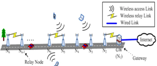
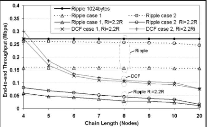
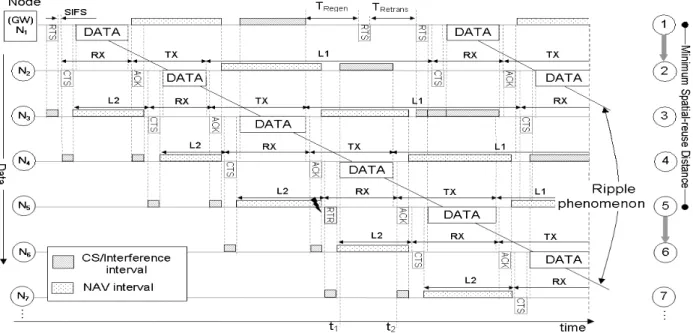
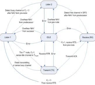
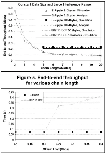
Quang Vu Nguyen and Ray-Guang Cheng, “Enhanced Ripple(E-Ripple) protocol for multihop wireless chain-based networks,”the 10th IEEE International Symposium on a World of Wireless, Mobile and Multimedia Networks (WoWMoM), June 2009.Radio Resource Allocation for Overlapping MBS Zones
Ray-Guang Cheng and Kuo-Jui Huang Department of Electronic Engineering National Taiwan University of Science and Technology
Taipei, Taiwan, R.O.C.
Email: {crg, M9602226}@mail.ntust.edu.tw
Jen-Shun Yang
Information and Communications Research Laboratories Industrial Technology Research Institute (ITRI)
Hsinchu, Taiwan, R.O.C.
Email: [email protected] Abstract— Multicast and broadcast service (MBS) is one of the
important services for next generation wireless systems. In WiMAX, the radio resource unit (i.e., time, frequency, code, etc.) for MBS is centralized allocated by a network device named Anchor ASN-GW. The ASN-GW has to ensure that non-overlapping radio resource units are allocated to BSs for delivering different MBS contents. This paper presents a method to allocate radio resource units in overlapping MBS Zones. We proposed radio resource allocation and re-allocation algorithms to minimize the number of re-allocated resource unit due to the change of MBS Zones topology. Simulation result shows that the proposed algorithms can reduce the number of re-allocations and thus, reduce the signaling message exchanged in the air interface and the core network.
Keywords- multicast and broadcast service (MBS), multimedia broadcast/multicast service (MBMS), radio resource allocation
I. INTRODUCTION
Multicast and Broadcast Services (MBS) (which is also known as multimedia broadcast/multicast services, MBMS in 3GPP LTE) is one of the important services to be supported by the 4th generation (4G) system. MBS is a point-to-multipoint service where data packets are transmitted simultaneously from a single source to multiple destinations [1]. MBS provides an efficient usage of radio/spectrum resources via transmitting the same data through a common broadcast or multicast channel. Potential MBS services include streaming services, file download services, and carousel services (combination of streaming and file download services aspects with repetition and update to reflect changing circumstances) [2].
Normally, the MBS content is transmitted over a geographical area identified as a zone. A cluster of base stations (BSs) that transmit the same content in a zone is referred as an MBS Zone. In an MBS Zone, the contents are identified by the same identifiers (IDs) and security association (SA) [3]. Hence, a mobile station (MS) in either connected state or idle state can continue to receive the content within the MBS Zone without re-establishing an MBS connection [1]. For MBS Zone containing multiple BSs, it can be operated in either macro diversity or non-macro diversity operating mode. In macro diversity operating mode, all BSs belonging to the same MBS Zone should be synchronized at
the symbol level (i.e., with timing errors within the cyclic prefix length) to transmit identical MBS contents using the same modulation and coding [4]. In non-macro diversity operating mode, synchronized transmission is not required but the same MBS content is coordinated to be transmitted in the same frame.
Each BS could be a member of more than one MBS Zone.
Two MBS Zones are overlapped if there is at least one BS belonging to both zones [5]. In MBS, a BS can dynamically join or leave an MBS Zone due to the moving of MSs. A BS may decide to join a nearby MBS Zone if a user requests for a new MBS service that is not existed in this cell but is available at this MBS Zone. In contrast, a BS which serves no MS in connected/idle state may not have to deliver MBS content.
Hence, the BS may decide to leave an MBS Zone and reuses the radio resource.
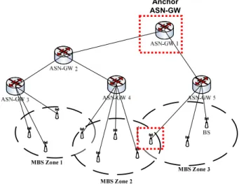
Anchor ASN-GW
Figure 1. MBS Zones and their associated Anchor ASN-GW.
Figure 1 shows an example of three overlapped MBS Zones. For each MBS Zone, an access service network gateway (ASN-GW) is responsible for controlling and allocating radio resource (i.e., which is defined in terms of time and sub-channels) for its subordinate BSs. For the network with multiple MBS Zones, the allocation is done by an Anchor ASN-GW [6]. In Anchor ASN-GW, a coordinating scheduling function is used to coordinate the transmission of MBS content across the entire set of the BSs that belong to the 2009 IEEE Mobile WiMAX Symposium
978-0-7695-3719-1/09 $25.00 © 2009 IEEE DOI 10.1109/MWS.2009.27
75
same MBS Zone. It has to reserve non-overlapping radio resource units such that BSs belonging to multiple MBS Zones may transmit individual MBS content without confliction.
There are two main constraints for allocating radio resources for MBS. First, the same radio resource unit may not be allocated to BSs to deliver more than one MBS content simultaneously. Second, the number of radio resource units required by the MBS Zones should be minimized.
The conflict-free radio resource allocation problem can be generally modeled as a vertex coloring problem. Coloring is a NP-complete problem for arbitrary random generated graphs [7]. Several approaches have been proposed to reduce the complexity via adding certain constraints. Woo, et al., [8]
proposed a method to divide a bus network into a number of sub-networks such that non-conflicting requests can be processed concurrently. A vertex coloring algorithm is then used to enable parallel communications. Walczak and Wojciechowski [9] proposed a scheduling method in multihop packet radio networks. They used a DSATUR graph coloring algorithm to determine a virtual path and find the conflict-free optimal scheduling. Zheng and Hoang [7] modeled the overlapping WLANs as a planar graph and used the Distance-1 vertex coloring technique to find the minimum number of re-use groups. In these approaches, the authors mainly focus on graphs with limited colors (e.g., two colors are considered in [8] and at most four colors are involved in [7]). In addition, the topologies considered in these approaches are rarely changed.
The radio resource allocation in overlapping MBS Zones can also be modeled as a vertex coloring problem [5].
However, each BS may have to transmit multiple MBS contents in a single frame and thus, results a rather complex topology. The topology may also be dynamically changed due to the moving of MSs. Hence, existing methods cannot be applied here. This paper presents dynamic radio resource management methods for overlapping MBS Zones. In initialization, the Anchor ASN-GW uses the radio resource allocation algorithm to allocate radio resource unit for a given topology. A radio resource re-allocation algorithm is then used to minimize the re-allocated resource units due to the change of topology. The reduction in the number of re-allocated resource unit not only reduces the computational complexity but also minimizes the signaling overhead in the air interface and the core network.
The rest of the paper is organized as follows. In Section II, a system model is presented and the proposed radio resource allocation and re-allocation algorithms are elaborated.
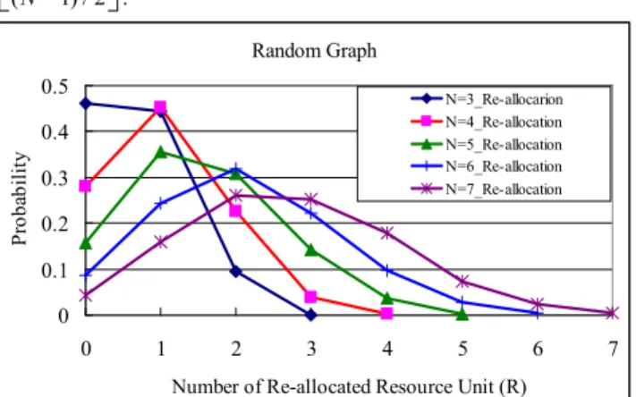
Simulation results were shown in Section III. The number of re-allocated resource units and the computational complexity of the proposed radio resource allocation algorithms were investigated. Section IV summarizes the conclusion.
II. SYSTEM MODEL
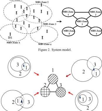
Figure 2 shows the system model used in this paper. In this model, the topology of MBS Zones is represented by an undirected labeled graph where each vertex represents an MBS Zone and the edge connecting two vertexes indicates the
overlapping of two MBS Zones [5]. The conflict-free radio resource allocation for overlapping MBS Zones can then be modeled as a vertex coloring problem where each color represents a radio resource unit. The graph should be colored in a way that no two adjacent vertexes share the same color.
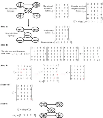
Note that, different topologies may map to the same non-isomorphic graph but have the identical resource allocation. Hence, we focus on the coloring of non-isomorphic graph. As shown in Figure 3, four network topologies may map to the same non-isomorphic graph. The resource allocation for these topologies is identical and thus, we may only focus on the coloring of non-isomorphic graphs herein.
MBS1 MBS2
MBS3
MBS5 MBS4 MBS Zone
1
MBS Zone 2
MBS Zone 3
MBS Zone 4 MBS Zone
5
MBS1 MBS2
MBS3
MBS5 MBS4 MBS Zone
1
MBS Zone 2
MBS Zone 3
MBS Zone 4 MBS Zone
5
Figure 2. System model.
Figure 3. Different topologies maps to the same non-isomorphic graph
In this paper, a N x N adjacency matrix X (XNxN) is used herein to represent the interconnectivity for a given topology containing N MBS Zones. Let xi,j be the i-th row and the j-th column element of X. Then we set
, 1, if MBS Zone and MBS Zone is overlapped, 0, otherwise.
i j i j
x =⎧
⎨⎩
Note that the adjacency matrix X is symmetric. That is,
, ,
j i i j
x =x . The purpose of the radio resource allocation and re-allocation algorithms is to find the resource unit vector (coloring vector) cJJKX for X.
The proposed radio resource allocation algorithm allocates radio resource units to each of the MBS Zone according to their degree. Therefore, conventional coloring algorithms (e.g., Welsh-Powell algorithm [10]) can be easily adopted to determine the resource unit vector for a given MBS Zone topology. However, the radio resource re-allocation algorithm further considers the correlation between the old and the new MBS Zone topologies to minimize the number of re-allocated
76
resource unit. Hence, it will only re-allocate the radio resource to those MBS Zones with modified edges.
The steps implementing the radio resource allocation/
re-allocation algorithms are summarized below.
A. Radio Resource Allocation Algorithm
Step 1: For a given N x N adjacency matrix X (XNxN), set
, 0, for {1, }.
xi i= i∈ N
Step 2: Find a degree vector dJJKX =[d1 d2 d3 " dN]
of matrix X, which is defined as
, 1 N
i i j
j
d = x
∑
=Step 3: Assign one resource unit to each MBS Zone.
Step 3.1: Initially, every vertex is uncolored. Let
0 1
C = − ⋅X
Step 3.2: Assign resource unit 1 to MBS Zone n (i.e., set
, 1
cn n= ) if MBS Zone n has the maximum degree (i.e., n arg max ,1i , i X
d = i d ≤ ≤i N d ∈dJJK
). Construct C1
by replacing the following elements in C0,
, , ,
, , ,
, if 1, {1, }, , if 1, {1, }.
i n n n i n
n j n n n j
c c c i N
c c c j N
= = − ∈
⎧⎨ = = − ∈
⎩
Step 3.3: Assign a used resource unit to MBS Zone m (set cm m, =1 if resource unit 1 is assigned) if the unassigned MBS Zone m has the maximum degree (i.e., m arg max ,1i , , i X
d = i d ≤ ≤i N i n d≠ ∈dJJK
) and does not yet have a neighbor with the used color.
Construct C2 by replacing the following elements in C1
, , ,
, , ,
, if 1, {1, }, , if 1, {1, }.
i m m m i m
m j m m m j
c c c i N
c c c j N
= = − ∈
⎧⎨ = = − ∈
⎩
Step 3.4: Repeat this process using extra resource unit until all vertex are assigned resource unit (i.e.,ci i, ≠0, {1, }i∈ N ). CN is obtained. Note that, color p can be assigned to MBS Zone q (i.e., set
,
cq q= ) if and only if p
, , ,
, , ,
, if 0 or 1, {1, }, , if 0 or 1, for {1, }.
q q i q i q
q q q j q j
c c c i N
c c c j N
≠ ≠ − ∈
⎧⎨ ≠ ≠ − ∈
⎩
Construct Ck by replacing the following elements in Ck-1: , , ,
, , ,
, if 1, {1, }, , if 1, {1, }.
i q q q i q
q j q q q j
c c c i N
c c c j N
= = − ∈
⎧⎨ = = − ∈
⎩
Step 4: The resource unit vector set is cJJKX =diag C( N).
B. Radio Resource Re-Allocation Algorithm
Step 1: Given the original adjacency matrix X. Set the resource unit reduction flag FC =0. Determine the adjacency matrix Y and its degree vector dJJKY
for the updated MBS Zones. Let yi,j as the i-th row and the j-th column element of Y, where
, 1, if MBS Zone and MBS Zone is overlapped, 0, otherwise.
i j i j
y =⎧
⎨⎩
, 1 N
i i j
j
d = y
∑
=Step 2: Determine C'N =CN+ ⋅k X Y( − ), where CN is the color matrix of the previous MBS Zones and C'N is the color matrix of the current MBS Zones, and k is a given constant that is no less than N.
Step 3: Focus on only the MBS Zones that have updated their topology, which are indicated by the non-zero elements in dJKX Y−
(i.e., the degree vector of matrix X-Y). Note that, newly added edges are indicated by elements with negative value in dJKX Y−
while newly deleted edges are indicated by elements with positive value in dJKX Y−
Start from the MBS Zone m that has the maximum value in dJJKY
, that is,
arg max ,1 , .
m i i i Y
d = d ≤ ≤i N d ∈dJJK
For elements in the m-th row/column in C'N that is negative (i.e., cm i, <0 or cj m, <0, 1≤i j N, ≤ , which represents newly added edges), use the color number used by zone m (i.e., cm,m) to replace this
element. , , ,
, , ,
, if 0, , {1, }, , if 0, , {1, }.
m i m m m i
j m m m j m
c c c i m N
c c c j m N
= < ∈
⎧⎪⎨
= < ∈
⎪⎩
The re-allocation may result in a conflicted decision at MBS Zone n if the two zones are overlapped and use the same resource unit. That is
, , and 0.,
n n m m n m
c =c c ≠
If conflicted decision is found, we may either i. Reset the resource unit of MBS Zone n (i.e., set
, 0
cn n= to zero) and then perform the radio resource allocation algorithm for those
, 0;
cn n= or
ii. Assign a non-conflicted resource unit (try to find a used resource unit first, and may use a new resource unit if no used resource units can be selected) to MBS Zone n (i.e., set it to a resource unit number).
For elements in the m-th row/column in C'N that is greater than N (i.e., cm i, >N, 1≤ ≤i N , which represents newly deleted edges), set its value to zero (i.e., ci m, =0 or cm j, = ) and set F0 C =1 (it indicates that some edges may be removed later).
Step 4: Repeat the process performed in Step 3 based on non-increasing order of degree of the MBS Zone until all elements in C'N are positive and none of them is greater than N. Then utilize the Step 2 of the radio resource allocation algorithm to deal with MBS Zones that do not assign resource units (i.e.,
77