Chapter 4 Principles and Concepts of proposed protocol
In MANET, a processor can be played as a sender, receiver, or relay, depending on the flow of a message. A message sent from a sender to a receiver may be passed through some intermedium (relay processors and links). The message may be contaminated by either the sender (dormant or arbitrary fault), intermedium, or both. In order to solve the fault-tolerant LE problem in such a network model, the aim of leader election algorithm is to make all fault-free processors to elect a common leader through the message exchange among processors. After message exchanged, all fault-free processors can use the received messages to decide the common decision leader.
4.1 Basic concept and approaches
Basically, leader election problem in a fault-tolerant mobile ad hoc network is the special case of Byzantine agreement problem [29, 35]. We use the oral message model of Byzantine agreement to support the LE protocol. The first work of the LE protocol is to determine the routing paths information which was obtained from the routing protocol after every topological change. Next, it generates a group secret key for each processor to encrypt the messages that must be sent with a digital signature. In addition, the encryption method is based on Identity-based digital signature scheme. Furthermore, we modify the MWV LE algorithm to supply the rules of our protocol, called LE mechanism. LE mechanism works after routing protocol to solve multiple changes occurring concurrently.
However, to solve the LE problem in a fault-tolerant mobile ad hoc network, the healthy condition of the network is not needed to know at the beginning of the proposed protocol, in brief, the values of Pa, Pd, La and Ld of constraints on failures as mentioned above is not
need to be known prior to execute our protocols.
After finish generating the group secret key, gathering routing paths information and the leader’s id which is determined by leader election generator with LE mechanism, the protocol needs to execute three steps of works in the fault-tolerant LE protocol. They are message encrypt step, message exchange step and leader election step. The message
exchange step consists of t+1 rounds to collect messages from other processors [29], where t=⎢⎣(n−1) / 3⎥⎦ . The task of the leader election step is to decide a common leader identifier, as shown in Fig. 4-1.
We must draw attention to the use of cryptography to ensure the safe communication.
In MANET, the encryption method is helpful to more easily remove the influences caused by a faulty intermedium in FTMC protocol presented below and reduce a great quantity of the message exchange rounds.
FTLE (Fault-Tolerant Leader Election algorithm) we proposed combines the following approaches to solve the LE problem in a fault-tolerant mobile ad hoc network:
- The Leader Election (LE) mechanism
LE mechanism is to determine the identifier of the new leader after every topological change. The rules are stated in following:
(L1): When a node detects a partition due to links failure, it elects itself as the new leader.
(L2): When a node detects a merging due to links formation, it elects its original leader as the new leader.
- The fault-tolerant message channel (FTMC) protocol:
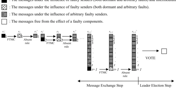
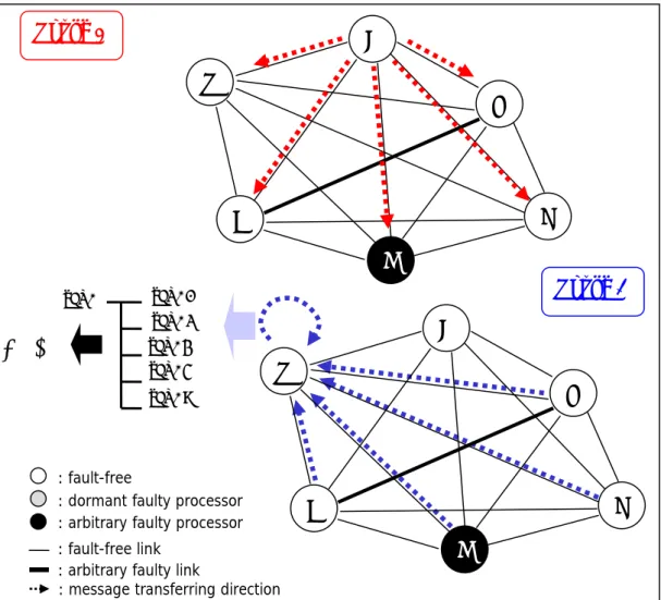
At the start of the message exchange, each sender uses FTMC to broadcast its message to all receivers, as shown in Fig. 4-1. The goal of FTMC is to remove the influence caused by a faulty intermedium. That means FTMC provides a reliable communication
mechanism in MANET so that the message passing in such a network is similar to that with fault-free communication links. Each receiver collects all of the sender’s messages that are free from the influences of a faulty intermedium when FTMC is applied as shown in Fig. 4-1.
- Absent rule:
The absent rule is applied at the end of the each round, namely rk+, to remove the influence of the dormant faulty sender, as shown in Fig. 4-1. Obviously, if a sender has a dormant fault, all fault-free receivers can detect such a fault (no message was received from it) during the entire message exchanged step or at some message exchanged rounds. Once a faulty sender is detected, a fault-free receiver will ignore the messages received from it in every subsequent message exchange round.
- The voting function VOTE:
After the message exchange step, the number of received messages collected is enough to remove the influence of an arbitrary faulty sender and to make each fault-free processor able to elect a common leader through a voting function VOTE taken in the leader election step, as shown in Fig. 4-1. VOTE counts the non-ds values. For all vertex σ at the ith level of an IG-tree, the output of VOTE depends on the following conditions:
(C1): val(σ), if σ is a leaf; or
(C2): val(σ), if 1 ≤ i ≤ t and σ has at least 3 * (t -i + 1) + [(n -1) mod 3] children, each of which has value ‘As’; or
(C3): v, if 1 ≤ i ≤ t, σ has no more than 3 * (t -i + 1) + [(n -1) mod 3] children, each of which has value ‘As’, v is the most common value of VOTE applied to children of σ, and v
≠RAi; or
(C4): As, if 1 ≤ i ≤ t, σ has no more than 3 * (t -i + 1) + [(n -1) mod 3] children, each of which has value ‘As’, and ‘RA1‘ is the most common value of VOTE applied to children of σ; or
(C5): RAj-1, if 1 ≤ i ≤ t, σ has no more than 3 * (t -i + 1) + [(n 1) mod 3] children, each of which has value ‘As’, and ‘RAj’ is the most common value of VOTE applied to children of σ, where j≠1; or
(C6): the default value ‘dv’, if no majority value of children of σ exists.
Conditions (C1), (C3), (C5), and (C6) are similar to the traditional majority vote. The other two conditions are used to handle the case of mixed faults. Semantically, condition (C4) is used to report the existence of an absentee. When the major number of processors reports that an absentee exists, VOTE returns the value ‘As’, an absentee’s vote, to represent such an event.
Fig. 4-1. The basic concept of FTLE.
- The data structure IG-tree:
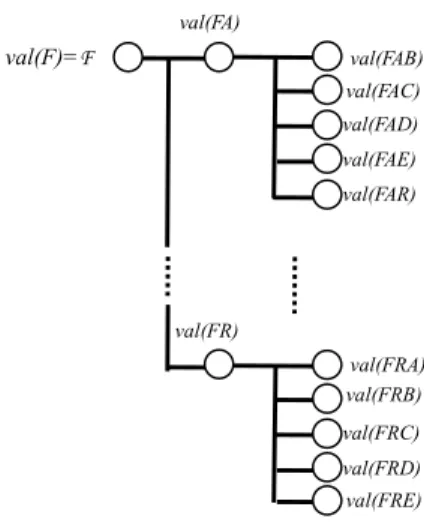
As for the data structure used to collect the messages, each fault-free processor maintains a tree structure, called the Information Gathering tree (IG-tree) [6], of level t+1, for collecting the received messages. Fig. 4-2 illustrates the structure of an IG-tree for the network as mentioned in Fig. 2-11. After the first message exchange round, each fault-free receiver stores the message received from the originator, denoted as val(F), at the root F of its IG-tree. In the second round, each processor broadcasts the root’s value of its IG-tree to all receivers. If processor B sends a message val(F) to processor A, A will store the message received from B, denoted as val(FB), at vertex FB of its IG-tree. The vertex FB is said to correspond to the sender B. Note that each level of an IG-tree contains a round of received messages and each vertex is labeled by a no repeating sequence of processor identifiers. Because the label of an IG-tree is no repeating, the root (labeled by the originator) has n-1 children and a vertex at the t-th level has n-t leaves as children as shown in Fig. 4-2. No repeating processor identifier can avoid the recursive influences
: The messages under the influence of faulty senders (both dormant and arbitrary faults) and intermedium.
: The messages under the influence of faulty senders (both dormant and arbitrary faults).
: The messages under the influence of arbitrary faulty senders.
: The messages free from the effect of a faulty components.
FTMC Absent rule
VOTE
Message Exchange Step Leader Election Step 1 1 1
FTMC Absent rule
2 2 2
r1- r1 r1+ r2- r2 r2+
FTMC Absent
rule
t+1 12 3
t+1 t+1
t t t 12
3
12 3 .
. . .
. . . .
. . . .
rt+1- rt+1 rt+1+
…
made by a faulty processor.
Fig. 4-2. The data structure of IG-tree.
We shall briefly outline our protocol which combines the approaches of FTMC, absent rule and voting function to solving the LE problem in MANET with the example as shown in Fig. 2-11. At the beginning, an originator, F, broadcasts its leader’s id which is determined by LE mechanism to all other processors, then the receiver R, receives the leader’s id from F at round 1. It’s not enough to remove influences of faulty components.
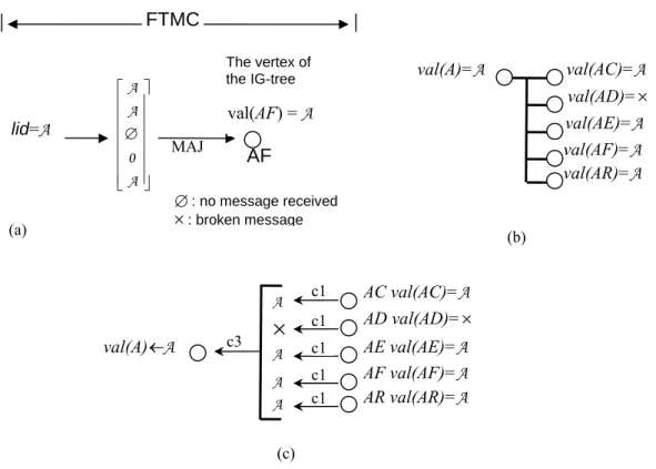
Except that R receives the message from F at first round, R needs information from other processors, which at first round they received messages from F. Actually the originator, F, uses FTMC to send c copies of the message along c paths to the receiver, R (c is the connectivity of the network). R takes a majority value from the c copies of the message as the value which F sent, as shown in Fig. 4-3.
Simultaneously, R collects the messages exchanged into its IG-tree, as shown in Fig.
4-4(a). The first level of IG-tree indicates that at the first round R received the leader’s id from A. The second level of IG-tree indicates that at the second round the leader’s ids R received.
val(F)=F
val(FA)
val(FR)
val(FAB) val(FAC) val(FAD) val(FAE) val(FAR)
val(FRA) val(FRB) val(FRC) val(FRD) val(FRE)
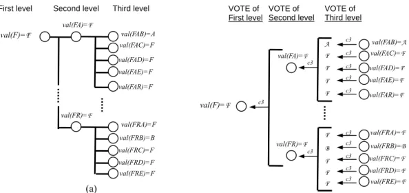
When t+1 finished, R has a complete IG-tree in this time. R applies a voting function, VOTE, on the IG-tree as shown in Fig. 4-4(b). The final output value of the IG-tree is the common and correct leader sent by originator F. The correct leader means that the leader’s id at beginning the sender sent and then passed through unsafe communication so that finally eliminated influences from faulty components.
Fig. 4-3. The sender broadcast its lid value to receiver along c (= 3) paths. It is obvious that receiver receives the value ‘×’, means that the message has been destroyed by faulty intermedium.
Fig. 4-4. (a) The first round and second round of IG-tree. (b) VOTE function.
×: broken message F
F
⎡ ⎤⎢ ⎥×
⎢ ⎥⎢ ⎥
⎣ ⎦ lid=F
val(F)=F MAJ F
The root of the IG-tree
FTMC
VOTE of First level
VOTE of Second level First level
(a)
val(F)=F
val(FA)=F
val(FR)=F
val(FAB)=A val(FAC)=F val(FAD)=F val(FAE)=F val(FAR)=F
val(FRA)=F val(FRB)=B val(FRC)=F val(FRD)=F val(FRE)=F Second level Third level
val(F)=F
val(FA)=F
val(FR)=F
val(FAB)=A val(FAC)=F val(FAD)=F val(FAE)=F val(FAR)=F
val(FRA)=F val(FRB)=B val(FRC)=F val(FRD)=F val(FRE)=F VOTE of
Third level
A F F F F
F B F F F
c3 c3 c3 c3 c3
c3 c3 c3 c3 c3 c3
c3 c3
4.2 The algorithm of FTLE
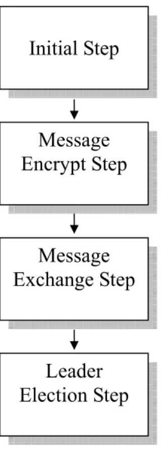
FTLE consists of (1) the Initial step, (2) Message encrypt step, (3) Message exchange step, and (4) Leader election step, to elect a common leader. The main functions of these steps are shown in Fig. 4-5.
Fig. 4-5. The procedure of FTLE.
Before the initial step of FTLE, a prior work is to determine the paths information by the routing protocol. When a processor detects that the network occurs merging or partition by routing protocol (we use the TORA protocol here). He will make a processing enter into the initial step of FTLE. We call the processor as the originator.
In “Initial Step,” the originator starts up the leader election process. First it determines the new leader by LE mechanism which is described in Section 2.4. Actually,
Message
Encrypt Step ‧ Use ID-based signature scheme to encrypt message to ensure the security of communication.
Message Exchange Step
Leader Election Step
‧ To tolerant faulty components, each processor must exchange and collect enough encrypted messages and decrypt the messages to construct a simple IG-tree.
Initial Step ‧ The election originator takes the initiative and determines the new leader of his connected component by LE mechanism.
‧ Apply VOTE to the IG-tree, each processor will get its LEADER through VOTE function.
when merging/partition occurs, there is usually over one originator to originate the election process. They determine the new leader’s id and then broadcast their new leader’s ids respectively.
In “Message Encrypt Step,” all processors execute the identity-based threshold key distribution scheme to establish the public key and the secret key for every processor. The originators encrypt the new leader’s ids with digital signatures and prepare to send out this message. We apply a digital signature algorithm to encrypt the sent/relayed message to remove the influences of relaying faulty processors. The digital signature algorithm is an identity-based signature scheme designed by Cha and Chcon [8].
In “Message Exchange Step,” FTLE needs t+1 message exchange rounds. In the first round, the originator, who will tell other processors the id of the leader, broadcast its message to all processors. In message passing, sender sends the message along c paths. In other words, each neighbor will receive c copies of one message from one sender.
In “Leader Election Step,” each processor applies VOTE function to its IG-tree. The correct leader’s id is the minimal identifier among the output values of VOTE applied to IG-tree. This id must be the same as the id which the originator announced if the originator is fault-free. Besides, all fault-free processors get the common leader’s id if n >
3 Pa + Pd and c > 2 Pa + Pd + 2(La + Ld).
The detail descriptions of the above steps for removing the influence caused by the multiple faulty components are presented as follows.
4.2.1 The encrypt method with digital signatures
At the time of network formation (the merging and the partition are generally called), a processor can use its node id, ID, to compute its public key. Let G be a group of prime order A . Choose a generator P of G, pick a random s∈Z/A, set Ppub = sP, and choose cryptographic hash functionsH1:{0,1}*× →G Z and /A H2:{0,1}*→ . The master key G is s. In the distribution of the secret key generation of the network, every processor can computes DID = sH2(ID) and output it as the private key associated to ID. QID = H2(ID) plays the role of the associated public key as mentioned in Section 2.5. The sender pick a random s∈Z/A, secret key QID and a message m as the parameters of the signature function to output the signature σ = (U, V) where U = rQID, h = H1(m, U), and V = (r + h)DID. The receiver verifies the signature by checking whether (P, Ppub, U + hQID, V ), where h = H1(m, U), is a valid Diffie-Hellman tuple. Using this method, we can detect the signature is whether destroyed or forged by faulty intermedium. In next sub-section, we will comment the coordination of FTMC and ID-based signature for removing the influences of faulty intermediums.
4.2.2 Removing the influence of a Faulty Intermedium
The function of FTMC is to remove the influence caused by the faulty intermedium between any pairs of processors. We first consider the case of a single sender S and a single receiver R. S uses FTMC to send its message m to R. Solving this case successfully will enable us to solve the general case in which every sender sends its message to every receiver.
Due to the Menger theorem [12], at least c disjoint paths exist between S and R if the connectivity of the network is c. Hence, S is able to send c copies of its messages through c disjoint paths to R. The c disjoint paths between S and R can be defined at “inital Step,”
as shown in Fig. 4-4, and then the paths information is established onto the relay processors between S and R. The detailed description of the paths information is presented in the last of this sub-section. According to the paths information, a relay processor receives the message (R, S, Ds(m)), Ds(m) is a message with an encrypted digital signature by processor S, from the defined immediate predecessor and sends the message to the predefined immediate successor. Since the network is synchronous, the predefined immediate successor P of S should have the message sent by S after the predefined time interval [17]; Otherwise, it knows that either S, the link LSP , or both are faulty. When P receives no message from S, it will relay the message Dp(∅ ) (Symbol ∅ ∉ V ) to its immediate successor along the predefined disjoint path between S and R to reflect the faulty status. These are the concepts of the transferring rules obeyed by each relay processor. The goal of the transferring rules is to make the receiver obtain the correct message sent, directly or indirectly, by the sender. The formal definition of the transferring rules is presented in the last of this sub-section.
By the definition of the transferring rules, normally, R receives only one S’s message from a path between S and R. If more than one message is received from a path in a mes- sage exchange round, then all messages received from the path are discarded. This method can handle the case of the faulty components to fake the messages of predecessors.
Therefore, R receives at most c messages sent by S. An arbitrary faulty intermedium between S and R can influence, at most, one message of these c messages sent by S, and a dormant faulty intermedium between S and R can drop, at most, one message of these c
messages sent by S. In the worst case, R will receive c - Pd - Ld copies of messages sent by S. By applying the majority vote MAJ to these messages, R can determine the message
sent by S if the constraint on connectivity, namely c > 2Pa + Pd + 2(La + Ld), holds. MAJ has three possible outcomes:
z Case 1: m, if S is fault-free.
z Case 2: ∅ , if S does not send the message to R.
z Case 3: Arbitrary value, if S has an arbitrary fault.
In Case 1, R can receive the message m sent by the fault-free sender S when MAJ is applied to the receiver messages. If S does not send the message to R (Case 2), R will use
∅ as the message sent by S because the major number of c - Pd - Ld copies of messages is
∅ . The third outcome of MAJ implies that the received message is not only contaminated by the faulty intermedium, but also is contaminated by the arbitrary faulty sender. FTmC is unable to remove the influence of such a case; hence such an outcome of MAJ shall be an arbitrary value.
Paths Information:
The paths information of each sender and receiver pair is distributed onto the replay processors between sender and receiver. Each relay processor P maintains a tuple (receiver, sender, predecessor, successor) path information such that the path <predecessor, P, successor> is a subpath of the path from the sender to the receiver. The sender and receiver also need the c neighbors along a prescribed set of processor-disjoint paths. The sender will send c copies of the message formatted (receiver, sender, message) through the c predefined paths to the receiver at each time of message passing.
The Transferring Rules:
The transferring rules obeyed by a relay processor P are defined in the following:
(TR1): According to the paths information described above, P only relays a message to its defined immediate successor if P receives it from its defined immediate predecessor.
(TR2): Let P be a defined immediate successor of the sender S. After the time Tk + TSP , if P does not receive a message from S, then P will relay the messages Dp(∅ ) to its defined
immediate successor, where Tk is the starting time of the kth round of the message exchange step, and TSP is the upper bound on communication time between S and P.
Semantically, (TR1) indicates that a fault-free relay processor only receives a message from the defined immediate predecessor and only sends a message to the defined im- mediate successor. (TR2) is proposed to help R to determine the status of S. At the time TSP after the starting time of the kth round, namely Tk + TSP , the defined immediate successor P of S should have the message sent by S; otherwise, it knows that either S, the link LSP , or both have failed. When P receives no message from S, it will relay the messages Dp(∅ ) to its defined immediate successor to reflect the faulty status.
4.2.3 Removing the influence of a Dormant Faulty Sender
While a fault-free processor collects the exchanged messages into its IG-tree, FTLE is going to remove the influence of a dormant faulty sender. Each fault-free sender should send its messages to all receivers in each round of the message exchange step. As mentioned in Section 4.2.2, a receiver can therefore detect that a sender is faulty if no message is received from the sender (the output of MAJ of FTMC is∅ ).
In the first round, the originator should broadcast its lid to all processors; therefore, a fault-free receiver R can always detect that the originator is faulty if no message is received from it. In order to satisfy the Agreement condition of the LE problem in MANET – agreement should be reached by every fault-free processor even if no message was sent from the originator. R will select the default value, say ‘ds’, to replace the originator’s message if no message is received from the originator. The default value is
‘NULL’ which means the originator is unavailable.
In each subsequent round, these n-1 receivers (except the originator) should exchange the message received from the originator to compute a common lid. A fault-free receiver R can detect that a sender S if faulty if no message was received from S. If R
receives no message from S at the r-th round, all messages received from S (directly) at the rth round and the subsequent rounds will be replaced by value ‘As’, and this value will be relayed to all processors as value ‘RA1’. In each subsequent round, the value RAj will be relayed to all processors as value RAj+1 (A∉V and i∀ , RAi∉V).
Semantically, the value ‘As’ is represented as an absentee vote, while sender S is treated as an absentee. Hence, the voting ticket of S is ignored during the leader election step. Value RAi will be interpreted as the ith time an absent vote reported. R will report to all processors that S is an absentee; thus, S has no influence on the others when the voting function VOTE is taken in leader election step. The approach can be formalized as follows:
Absent rule:
When R receives no message directly from S in the rth round, then (AR1):
1) If r = 1 (the first round), P will select the default value ‘dv’ to replace the incoming message from S (the originator); or
2) If r≠1, all messages received from S at the rth round and any subsequent rounds will be replaced by value ‘As’, and this value will be relayed to all processors (except the transmitter) as value ‘RA1’.
(AR2): When R receives the value RAj, it will relay the value RAj+1 to all processors (if any).
4.2.4 Removing the influence of an Arbitrary Faulty Sender
After the message exchange step, the messages collected in a fault-free receiver’s IG-tree are free from the influence of the faulty intermedium and the dormant faulty sender. However, the messages are still contaminated by the arbitrary faulty senders. In order to elect a common leader, such an influence shall also be removed in the leader
election step. As mentioned in Section 4.1, the traditional majority vote is inappropriate in mobile ad hoc network. As a result, we proposed a new scheme VOTE to remove the influence of the arbitrary faulty senders.
By the constraint on the number of processors required, namely n >3Pa +Pd , if the network eliminates one arbitrary faulty sender, then it can tolerate three more dormant faulty senders because 3(Pa - 1) = 3Pa +Pd , where Pa ≥ 1.
This phenomenon can be used by VOTE to remove the influence of an arbitrary faulty sender. The basic concept of VOTE is as follows: Let P be a fault-free processor and σ be a vertex at the i-th level of P’s IG-tree, 1 ≤ i ≤ t. If P detects that 3 * (t -i + 1) + [(n -1) mod 3] children of σ have value ‘As’, it will use the original value stored at o-, namely val(σ), as the output of VOTE for removing the influence of the arbitrary faulty sender as in the above discussion; otherwise, it will use the majority value of children of σ as the output of VOTE.
VOTE is always correct if vertex σ corresponds to a fault-free or a dormant faulty sender, since each fault-free receiver has the same message sent by the sender. On the other hand, if vertex σ corresponds to an arbitrary faulty sender Q, the output of VOTE may be contaminated by Q after our approach is applied (Q cooperates with other arbitrary
faulty senders to prevent the fault-free processors from achieving a common value).
However, the influence of Q can still be removed if n > 3Pa +Pd . Therefore, the fault-free processors can elect a common leader through the concept of democratic voting, as shown in Theorem 4. Finally, the output value of VOTE may reflect that the originator is a faulty processor.
Next, we introduce our protocol in the following cases:
(1) The processors and intermediums are fallible in broadcast network.
(2) The processors and intermediums are fallible in general case network.
4.3 Examples of Algorithm
4.3.1 The case of the broadcast network with mixed faults on both processors and links
Broadcast network, in other words, is fully connected topology as show in Fig 4-6.
In this topology, every processor can link to others by directed link. The connectivity of the topology is |N|-1, N is the set of all processors. As shown in Fig. 4-6, we assume that n
= 6, c = 5, Pa = 1, Pd = 0, La = 1 and Ld = 0.
In this case, we consider that every connected component is fully connected MANET, even if merge or partition occurs. In other words, a fully connected component is finally generated when two or more fully connected components are merged.
In current scenario, A originates the process of leader election due to detecting a partition. According to the rules of LE mechanism, A elects itself as the new leader and executes the ID-based threshold key distribution scheme to establish the public key and the secret key. Subsequently A broadcasts the message which contains the new leader’s id to every neighbor (R, C, D, E and F) by FTMC at round 1. In this time, the neighbor, say R, receives five copies of the message from A along five disjoint paths. By MAJ rule, R
gets a value = ‘A’ and stores it at the root of R’s the IG-tree, val(A). At the start of round 2, R sends the root value of R’s the IG-tree, val(A) = ‘A’, to other neighbors (C, D, E and F)
by FTMC. The other neighbors do the same work as the same as R. Immediately, R receives five copies of the message from F along five disjoint paths. By MAJ rule, R gets a value, ‘A’ from F and stores it at the second level of R’s IG-tree, val(AF) as shown in Fig.
4-7(a). For this reason by analogy, R receives values from C, D, E and R and stores them at the second level of R’s IG-tree, val(AC), val(AD), val(AE) and val(AR) respectively. We assume that val(AC) = A, val(AD) = X, val(AE) = A, val(AF) = A and val(AR) = A as shown in Fig. 4-7(b). Finally, in the “Leader Election step” of FTLE, R applies VOTE to its IG-tree and get the output value, ‘A’ as shown in Fig. 4-7(c). At the same time, all fault-free processors also elect processor A as the common leader.
Fig. 4-6. The case of the broadcast network with mixed faults on both processors and links (n = 6, c = 5, Pa = 1, Pd = 0, La = 1, Ld = 0).
val(A) val(AC) val(AD) val(AE) val(AF)
VOTE
: fault-free
: dormant faulty processor : arbitrary faulty processor : fault-free link
: arbitrary faulty link
: message transferring direction val(AR)
Round 1
Round 2 A
R F
E D
C
A
R F
E D
C
Fig. 4-7. (a) F sends five copies of message to R along five disjoint paths in the second round. (b) R’s IG-tree after the second round message exchanged. (c) Apply VOTE to R’s IG-tree in the “Leader Election step”.
4.3.2 The general case of MANET with mixed faults on both processors and links
The general case of MANET, semantically, means that the network topology need not be fully connected. If the constraints on failures, namely n > 3Pa + Pd,, c > 2Pa + Pd + 2(La + Ld), hold, the common leader can be elected by using FTLE algorithm. We take a example for this case as shown in Fig. 4-8 (n = 7, c = 3, Pa = 1, Pd = 0, La = 0, Ld = 0).
In general case network, we still apply the four steps shown in Fig 4-5. The differences between this case and broadcast network are that the connectivity of the topology is less than |N|-1. Therefore, a sender sends a message to other processor via relaying processors and links. For example, Fig. 4-8 illustrates the merging of the connected components. As described in Fig. 4-8(a), two processors, say A and H, join to
val(A)=A val(AC)=A val(AD)=× val(AE)=A val(AF)=A
(a) (b)
val(AR)=A
∅: no message received
×: broken message
⎡ ⎤
⎢ ⎥
⎢ ⎥
⎢∅⎥
⎢ ⎥
⎢ ⎥
⎢ ⎥
⎣ ⎦ A A
0 A
lid=A val(AF) = A
MAJ AF
The vertex of the IG-tree
FTMC
(c) val(A)←A
AC val(AC)=A AD val(AD)=× AE val(AE)=A AF val(AF)=A AR val(AR)=A A
A A A
×
c1 c1 c1 c1 c1 c3
the network and the network is reconfigured as shown in Fig. 4-8(b).
Fig. 4-8. Processor A and H join to the original network to form a new general case network. With the movement of A and H, the new constraints on failures of the new network take shape. (n = 9, c = 4, Pa = 1, Pd = 1, La = 0, Ld = 0)
The merging status is detected by processors A, B, C, D, E, F, R, G and H, according to the rules of LE mechanism (L2) and ID-based threshold key distribution scheme, each of the processor acts as the originator of LE algorithm. Of course, the constraints on failures of the newly formed network may change in a measure. Then, subsequently each originator enters in the following steps of FTLE as shown in Fig. 4-5. Each originator broadcasts the message which contains the new leader’s id to all processors excluded itself by FTMC at the first round. By FTMC, receiver obtains four copies of the message from the sender along four disjoint paths as shown in Fig. 4-8(b).
This is a typical example for concurrent topological changes. A change (link failure or link formation) occurs, another change may occurs before the network has finished recovering from the previous change. In this situation, LE mechanism based-on TORA protocol is easy to accomplish. But in a fault-tolerant environment, we elect a common
(a)
G
B
C
D
E R F
H
A : fault-free
: dormant faulty : arbitrary faulty : fault-free link : dormant faulty link
(b)
G
B C
D
E R H F
A
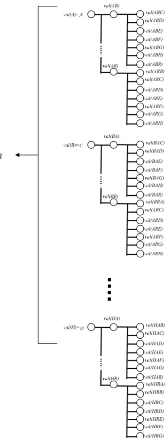
leader depended on the IG-tree which collected messages from the message exchanges. In FTLE, each fault-free processor maintains an IG-tree to decide the common leader. When more one originators start the election process like the example as shown in Fig. 4-8, of course, each fault-free processor maintains not only one IG-tree as shown in Fig. 4-9. In other words, each fault-free processor maintains IG-trees which collect messages from message exchanges caused by all originators in this topological change. To base on LE mechanism, we can identify the newest election by checking the reference level of the election message as mentioned in section 2.4. Therefore, we can maintain correct IG-tree and drop the messages out of session. After applying VOTE to every IG-tree, finally each fault-free processor can obtain more than one leader’s ids. By LE mechanism, we decide the minimal identifier as the new leader in this topological change as shown in Fig. 4-9.
Fig. 4-9 When more than one originators starts the election process, FTLE selects the minimal identifier among all IG-tress as its output value.
val(A)=A
val(AB)
val(AR)
val(ABC)
val(ABD) val(ABE) val(ABF) val(ABG) val(ABH) val(ABR) val(ARB)
val(ARC) val(ARD) val(ARE) val(ARF) val(ARG) val(ARH)
val(B)=C
val(BA)
val(BR)
val(BAC)
val(BAD) val(BAE) val(BAF) val(BAG) val(BAH) val(BAR) val(BRA)
val(ARC) val(ARD) val(ARE) val(ARF) val(ARG) val(ARH)
val(H)=∅
val(HA)
val(HR)
val(HAB)
val(HAC) val(HAD) val(HAE) val(HAF) val(HAG) val(HAR) val(HRA)
val(HRB) val(HRC) val(HRD) val(HRE) val(HRF) val(HRG)
A
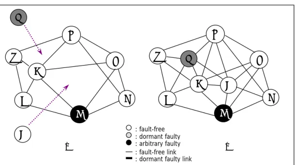
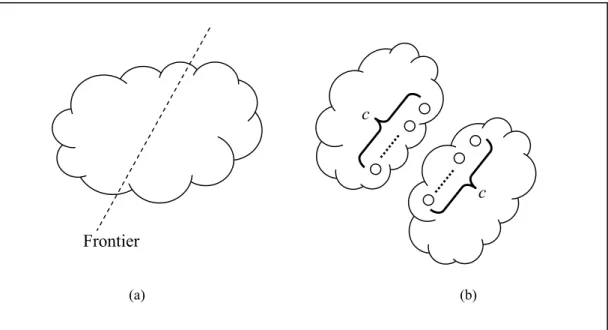
We shall consider the case of partition as shown in Fig. 4-10.
Fig. 4-10. The example of partition occurring. (a) A separate frontier exists at the partitioning component. (b) There are at least c processors to detect the partition.
If the connectivity of the original connected component is c, there are at least c originators at the separate frontier in each connected component when the partition occurs.
These originators elects their own ids by the rule of LE mechanism (L2). All fault-free processors execute FTLE and then obtain at least c IG-trees. Each fault-free processor selects the minimal identifier as its new leader among these outputs while applying VOTE to these IG-trees.
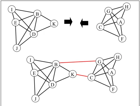
4.3.3 In Extreme case network
The extreme case is an extension of general case. As shown in Fig 4-11, for example, while two highly connective network is merged with two connecting links, B-G and K-C.
After merging or partition, the constraints on failures of the network have been changed. If the new constraints on failures are satisfied, namely n > 3 Pa + Pd and c > 2 Pa + Pd + 2(La + Ld), FTLE will enable all fault-free processors to elect a common leader.
(a) (b)
Frontier
c
c
Fig. 4-11. The extreme case network.
4.4 Correctness
The goals of FTLE are listed in section 3.3. The correctness of FTLE can be proven from the fact that the common leader of each fault-free processor satisfies the conditions of the number of allowable fault-tolerant components and the overhead of communication.
To elect a common leader in MANET, each fault-free processor should be insulated from the influence of all faulty components. The basic concept of proving the correctness of FTLE is as follows:
1. By the rules of LE mechanism, the election originator determines the new leader’s id.
2. By using FTMC, FTLE first removes the influence of a faulty intermedium. Then, it makes each fault-free processor elect a common leader after the influence of the faulty sender is removed (both arbitrary and dormant faults). To prove the correctness of
I B
K D
E
J
G H
A
F C
I B
K D
E
J
G H
A
F C
FTMC, the output of MAJ should be proven to be free from the influence of a faulty intermedium. Hence, we shall prove that a fault-free receiver can receive the message sent by a fault-free sender.
4.4.1 The proof of LE mechanism
We show that the algorithm “eventually” brings the network to stable state even after a series of concurrent events. We show that after the concurrent events cease, the network comes to stable state within a finite amount of time as shown in Theorem 2.
We have analyzed the concurrent events as follows: an analysis of the state of each component before the last event in a series of concurrent events and how the component stabilizes after the last event. Our analysis is independent of the previous trigger events and is based only on the nature of the last trigger event. We have studied the various possibilities for the last concurrent event in order to facilitate the analysis. The classification is done based on the nature of the concurrent event as follows:
z Case1: Concurrent events that do not partition the component in which they occur.
z Case2: Concurrent events that partition the component in which they occur.
z Case3: Concurrent events that merge two components.
Proof of case 1:
When a link disconnects but not partitions the component, we just update the connectivity rather than originate an election process. Thus we show that there is only one leader in a stable connected component.
Proof of case 2:
When a link disconnects and partitions the component, there is at least one node at the Theorem 2. Given a time T, the network will come to a stable state within a finite time after T after which are no trigger events in the network.
separate frontier. It has no path to its leader due to the disconnected link and then originates an election process to elect a new leader in which the connected component the originator is. Therefore, when over two elections have been originated, all processor select the minimal id who has as his new leader. So we show that there is one and only one leader in a stable connected component.
Proof of case 3:
When a link forms and merges the two components, there are at least two nodes at the merging frontier. They update their connectivity and then originate election processes which contain their original leader’s id. Finally all processors in this connected component selected the minimal id who has as their new leader. Thu, we show that there is one and only one leader in a stable connected component.
4.4.2 The proof of FTLE
To prove the correctness of FTMC, the output of MAJ should be proven to be free from the influence of a faulty intermedium. Hence, we shall prove that a fault-free receiver can receive the message sent by a fault-free sender or can detect that the sender did not send a message to it.
Lemma 1. Using FTMC, a fault-free receiver R can receive the message m sent by a fault-free sender S if c > 2Pa + Pd + 2(La + Ld).
Proof: Using FTMC, the fault-free sender S sends c copies of m to R through c disjoint paths. According to the paths information and transferring rules presented in section 4-2-2, each dormant faulty intermedium (processor and link) can drop at most one message of these c messages. In the worst case, R has at least c –Pd –Ld messages sent by S. By hypothesis, we know that c –Pd –Ld > 2Pa + 2 La + Ld. Therefore, R can decide the message sent by S when the majority vote MAJ is applied to these c –Pd –Ld messages.
Then, we prove that FTLE makes each fault-free processor elect a common leader.
Since FTLE is based on the oral message model, some concepts and terminologies used by [6] are used here. A vertex σ is called common [6] if the value stored at σ of each fault-free processor’s IG-tree is identical. In other words, a common leader for a leader election can be reached if the root of each fault-free processor’s IG-tree is common. If every root-to-leaf of and IG-tree contains a common vertex, then the collection of the common vertices forms a common frontier [5]. To prove a common leader for a leader election can be reached by FTLE, we define consistent vertex as follows.
Consistent vertex: Vertex α (= σi) at a fault-free receiver’s IG-tree is a consistent vertex if
sender i is fault-free or in dormant faulty. By the behavior of i, all fault-free receivers receive the identical message sent by i. Although a receiver does not know which vertex is consistent, the consistent vertices do exist since some senders in the network are fault-free or dormant faulty.
Theorem 3. FTMC does remove the influence of a faulty intermedium in a mobile ad-hoc network if c > 2Pa + Pd + 2(La + Ld).
Proof: By Lemma 1 and 2, the message received by R is free from the influence of a faulty intermedium; thus, the theorem is proved.
Lemma 2. Using FTMC, a fault-free receiver R can detect the sender S does not send a message to it if c > 2Pa + Pd + 2(La + Ld).
Proof: when S does not send a message to R, each fault-free immediate successor of S (along the disjoint paths between S and R) will relay the symbol ∅ to R. In the worst case, R receives at least c – (Pd – 1) –Ld messages of value ∅ . By hypothesis, we know that c – (Pd – 1) –Ld > 2Pa + 2 La + Ld Hence, the output of the majority vote MAJ is ∅ , and R notices that S did not send a message to it.
The following lemma proves that all consistent vertices of an IG-tree are common:
Lemma 3. All consistent vertices are common after VOTE is applied to an IG-tree if n > 3Pa+Pd.
Proof: Each consistent vertex o of an IG-tree can be proven as common in the following cases.
Case 1: σ is a leaf.
Fault-free and dormant faulty senders always send identical message to all receivers. Hence, σ is common after VOTE is applied to σ.
Case 2: σ is at the i-th level, 1≤ i ≤ t.
Subcase 2.1: σ has at least 3 * (t -i + 1) + [(n -1) mod 3] children, each of which has a stored value ‘As’. By condition (C2) of VOTE, the original value stored at σ, namely val(σ), is used as the output of VOTE; thus, σ is common.
Subcase 2.2: σ has k (< 3 * (t -i + 1) + [(n -1) mod 3]) children, each of which has a stored value ‘As’. According to the structure of the IG-tree, σ has n-i children. by hypothesis, we have n –Pa – Pd > 2Pa. Since t≥ Pa, we have n – i ≥ n - t ≥ n - Pa; moreover, k≤ Pd, we can write n - i - k > 2Pa. Hence, by condition (C3), (C4) or (C5) of VOTE , σ is common.
Case 3: σ is the root.
According to the structure of the IG-tree, σ has n-1 children. If no arbitrary faulty processor exists in the network, namely Pd = 0, the children of σ are subjected to a dormant faulty only. These influences are removed by using the absent rule;
therefore, σ is common. On the other hand, suppose that some senders in the network are subjected to arbitrary faults, namely Pa≥1. By hypothesis, we have, n –Pa – Pd > 2Pa. Since Pa≥1, we can write,
n – 1≥n – Pa,
=> n – 1 – Pd ≥ n – Pa – Pd > 2Pa
=>n – 1 > 2Pa + Pd.
Hence, σ is common after the VOTE is applied.
By frontier lemma of [6], the root of the fault-free processor’s IG-tree is common if the common frontier exists on each fault-free processor’s IG-tree. The following theorems prove that a common leader can be elected among each fault-free processor.
Theorem 5. FTLE does solve the leader election problem in a fault-tolerant mobile ad hoc network with mixed faults if n > 3Pa+Pd and c > 2Pa + Pd + 2(La + Ld).
Proof: By Theorem 4, the agreement condition is satisfied. The valid condition is used when originator is fault-free. Since the originator is fault-free, all other fault-free processors receive the originator’s new leader’s id, lid, at the first round.
Subsequently, these processors execute message exchanges to verify the message received from the originator. Therefore, the consistency vertices of each fault-free processor’s IG-tree are lid. By Lemma 4, the root of each fault-free processor’s IG-tree is consistent because the originator is fault-free. By Theorem 4, the root is common and the value stored in the root of a fault-free processor’s IG-tree is lid.
Thus, the valid condition is satisfied. The theorem is proven.
Theorem 4. The root of a fault-free processor’s IG-tree is common.
Proof: From Lemma 4 and the frontier lemma of [6], the theorem is proven.
Lemma 4. The common frontier does exist in the IG-tree.
Proof: By the definition of the IG-tree, each root-to-leaf path consists of two vertices. Since the maximum number of arbitrary faulty processors is Pa
(≤⎢⎣(n−1) / 3⎥⎦), each root-to-leaf path has at least one consistent vertex. By Lemma 3, a consistent vertex is common. Therefore, the common frontier does exist in the IG-tree.
4.5 Complexity
The complexity of FTLE is defined in terms of 1) the number of messages required,
2) the number of faulty components allowed, and 3) the number of memory used.
In this subsection, we prove that FTLE is optimal. It uses the minimum number of rounds and messages to tolerate the maximum number of faulty components.
Theorem 6. FTLE requires t+1 rounds and one transaction of the ID-based threshold key distribution. O(ts*n + c(n-1) + tc(n-1)2) messages are required for solving leader election problem in fault-tolerant mobile ad-hoc network if n >
3Pa+Pd and c > 2Pa + Pd + 2(La + Ld) , where ts = the threshold value of the ID-based threshold key distribution.
Proof: The messages passing are needed in the message exchange step only; thus FTLE requires t+1 rounds. As mentioned in section 4-1, a sender uses FTMC to send its messages to a receiver for removing the influence of a faulty intermedium (c copies of its message are sent). At the first round, the originator broadcasts its new leader’s id to all other receivers; thus, c(n-1) messages are generated.
Subsequently, each sender broadcast its message to all receivers (excluding the originator) in the each exchanged round; thus, O(tc(n-1)2) messages will be yielded.
Furthermore, FTLE needs O(ts*n) messages in message encrypt step for exchanging key parameter and for establishing the secret key. Therefore, the total number of message required FTLE is O(ts*n + c(n-1) + tc(n-1)2). By theorem 4, FTLE can make each fault-free processor elect a common leader. Hence, the theorem is proven.
Theorem 9. The total number of memory usage by FTLE, namely O(nt).
Proof: By Theorem 6, FTLE requires t+1 rounds to exchange messages. As stated in the definition of the IG-tree in section 4.1, a vertex at the t-th level has n-t leaves as children as shown in Fig. 4-2, where t=⎢⎣(n−1) / 3⎥⎦ . Therefore, there are 1 (× − × − ×⋅⋅⋅× − vertices in each IG-tree. When k originators initiate n 1) (n 2) (n t) elections, each processor maintains at most k IG-tees, where k≤n. We need O(nt) of memory usage to solve the LE problem. Hence, the theorem is proven.
Theorem 8. The total number of allowable faulty components by FTLE, namely Pa + Pd + La + Ld, is maximum if n > 3Pa+Pd and c > 2Pa + Pd + 2(La + Ld).
Proof: By Theorem 1, a protocol for LE problem in a fault-tolerant mobile ad hoc network does exist if the constraints on failures, namely n > 3Pa+Pd and c > 2Pa + Pd + 2(La + Ld), hold. Otherwise, a common leader cannot be elected. If Pa + Pd + La + Ld is not the maximum number of allowable faulty components, then other constraints on failures should be exist, namely n≤3Pa+Pd and c≤2Pa + Pd + 2(La + Ld). However, this is a contradiction with the Theorem 1. Thus, the theorem is proven.
Theorem 7. FTLE solves leader election problem in fault-tolerant mobile ad hoc network by using the minimum number of rounds and messages.
Proof: If the system’s faulty status is unknown, then t+1 rounds are proven be the lower bound on message passing for reaching an agreement under mobile ad hoc network [19, 35]. To remove the influence of multiple faulty components, by Theorem 6, O(ts*n + c(n-1) + tc(n-1)2) is the lower bound on the number of messages required for electing a leader. Hence, the theorem is proven.