國立臺灣大學工學院化學工程學研究所 碩士論文
Department of Chemical Engineering College of Engineering
National Taiwan University Master Thesis
聚丙烯腈基在鋰離子電池矽碳負極複合材料上之應用 Applications of PAN on Si/C Composite Anode Material
for Lithium Ion Battery
許銘麟 Ming-lin Hsu
指導教授:吳乃立 博士 Advisor: Nae-Lih Wu, Ph.D.
中華民國 103 年 6 月
June, 2014
致謝
完成一份論文,是一件很浩大的工程,這並不是單單一個人就可以解 決的問題,除了需要教授、委員的指導之外,還需要有學長姐的幫助,寫 論文過程中,需要跟各式有經驗的人請教、討論;在心煩意亂寫不出來時,
還需要身邊的好友來支持你。
首先,要感謝吳乃立老師的指導。當初進這個實驗室時,還沒有做過 專題的經驗,心中也沒有甚麼大方向,老師從頭開始諄諄教誨。在實驗遇 到問題時,在跟老師討論時總會獲得新的收穫,即使不能當下解決問題,
也能從這次的面談中找出一絲曙光。在我實驗遇到困難時,老師總是願意 給我意見,我在轉換題目時一度預到很大的挫折,也都是因為老師悉心指 導,才能有現在的成果。
其次,要感謝現在實驗室的同儕們。我的各種實驗技巧、儀器的操作,
都必須從學長姐身上習得。此外,由於老師常常出國研討,每每遇到問題 時,第一時間不一定能找到老師提問,這時就需要同學之間的討論,在每 次 group meeting 時,總是可以從同學的報告中獲取新知。如果沒有這些 同學的支持,這份論文不可能這麼容易完成。
最後,還要感謝工研院的各位學長姐,提供我們做實驗的空間跟良好 的環境。以及總是幫我們處理財務的曉婷。就是因為有各位在背後支持,
我在能立足於此,完成這份論文。
摘要
在過去的十年中,鋰離子電池已在手機等電子零件的市場中成為主 流。目前,商業上用的負極碳基底材料具有低工作電位、高可逆性以及低 成本等優點,然而,碳基底負極材料的理論比電容量低(372 mAh/g)。在 替代的材料之中,矽材料因為具有高的比電容量低(~3500mAh/g)而受到關 注,但是,低導電度的特性跟鋰化時造成的劇烈體積膨脹收縮阻礙了矽負 極材料在商業化的應用。
在本本論文中,我們以開發矽主體的鋰離子二次電池負極材料為目 的。根據前人的研究,我們可以知道矽碳複合材料可以改善上述矽應用在 鋰離子電池所遭遇到的問題。我們以溶液塗佈法在矽碳複合材料上批覆一 層聚丙烯腈薄膜。在批覆聚丙烯腈之後,比電容量跟循環性能皆有改善。
此外,我們在原有的電解液中加入氟代碳酸乙烯酯以改善循環性能。
結果顯示,跟未在電解液中加入氟代碳酸乙烯酯的數據比較,總體的庫倫 效率跟循環後的比電容量都有增加。
最後,本研究也利用預置鋰遷入法來改善第一圈的庫倫效率,實驗結 果顯示,第一圈庫倫效率確實提升了,因此它未來十分有潛力被實際應用 在鋰離子電池的製程中。
關鍵字:鋰離子電池、矽、聚丙烯腈、氟代碳酸乙烯酯
Abstract
Lithium ion batteries have been dominating the market for mobile electronic devices for decades. Commercial anode graphite material has advantage of low working voltage, high reversibility and low cost. However, the major disadvantage is its low theoretical capacity of 372 mAh/g. Silicon is the most promising alternative material for its high theoretical specific
capacity(~3500mAh/g) and low alloying potential versus Li. However, low electronic conductivity and dramatic volume expansion upon lithiation hinder the commercialization of Si-based anode.
In this study, the main objective is to find new Si-based anode materials for lithium-ion battery. According to previous studies, the Si/C composites have overcome some cycle-life problems of silicon. We use solution coating method to coat porous Si/C composites with a thin Polyacrylonitrile (PAN) layer.
Capacities and cycle performance were enhanced after PAN-coating.
Moreover, FEC was added into EC/ EMC electrolyte to enhance cycle performance. The results showed overall coulombic efficiency and capacity after cycling were increased compared to previous PAN-coated Si/C
composites electrode.
Finally, the pre-lithiation approach was adopted to enhance the coulombic efficiency in the first cycle. First cycle coulombic efficiency was increased
after pre-lithiation approach. This result indicated that this approach is effective and has the potential for practical use.
Keywords: Lithium-ion batteries; silicon; poly-acrylontrile; fluoroethylene carbonate;
Table of Contents
致謝 ... I
摘要 ... II Abstract ... VI Table of Contents ... V List of Figures ... VII List of Tables ... IX
Chapter 1 Introduction ... 1
Chapter 2 Theory and Literature Review ... 3
2.1 Background and Fundamental Knowledge for Lithium-ion Batteries .. 3
2.2 Introduction to Carbonaceous and Si Anode Materials ... 8
2.2-1 Carbonaceous Anode ... 8
2.2-2 Si Anode ... 11
2.2-3. Silicon/Carbon Composite Anode ... 15
Chapter 3 Experimental ... 22
3.1 Chemicals ... 22
3.2 Synthesis of Anode Materials ... 24
3.2-1 Preparation of PAN-coated Si/C Composites ... 24
3.2-2 Electrode and Coin Cell Assembled ... 26
3.2-3 Preparation of PAN film Composites ... 29
3.2-4 Pre-lithiation Approach for Porous Si/C Composite ... 31
3.3 Electrochemical Characterization ... 32
3.3-1 Charge and Discharge Strategies ... 32
3.3-2 Electrochemical Impedance Spectroscopy ... 34
Chapter 4 Results and Discussions ... 35
4.1 Si/C Composites Electrode ... 35
4.2 PAN-coated Si/C Composites Electrode ... 40
4.3 Characterizations of PAN-coated Si/C Composites FEC/EC/EMC electrolye... 45
4.4 Pre-lithiation Approach ... 48
Chapter 5 Conclusion ... 50
References ... 52
List of Figures
Figure 2-1. Comparison of the gravimetric and volumetric energy densities of
various rechareable batteries system [1]. ... 5
Figure 2-2. Schematic illustration of the charge/discharge process in a lithium-ion cell consisting of lithium insertion compounds as both anode and cathode [2]. ... 7
Figure 2-3. The faces of graphite crystallite. ... 9
Figure 2-4. Li-Si phase diagram [26]. ... 13
Figure 3-1. Experimental flowchart of fabrication of PAN-coated Si/C. ... 25
Figure 3-2. Flowchart of preparing electrode by casting method. ... 28
Figure 3-3. Schematic drawing of a coin cell. ... 28
Figure 3-4. Experimental flowchart of fabrication of PAN-thin-film electrode. ... 30
Figure 3-5. Experimental flowchart of running cycles. ... 33
Figure 4-1. Cycle tests for electrodes of Si/C: (a) cycle Process A (b) cycle process B. ... 38
Figure 4-2. Coulombic efficiency versus cycle for electrodes of Si/C. ... 39
Figure 4-3. Nyquist plots for electrodes of Si/C . ... 39
Figure 4-4. Cycle tests for electrodes of Si/C and 3%PAN-coated Si/C: (a) cycle Process A (b) cycle process B. ... 42 Figure 4-5. Coulombic efficiency versus cycle for electrodes of Si/C and
3%PAN-coated Si/C. ... 43 Figure 4-6. Nyquist plots for electrodes of Si/C and 3%PAN-coated Si/C. ... 43 Figure 4-7. Cycle tests for Si/C electrodes for different amount of PAN coating and different electrolyte: (a) cycle Process A (b) cycle process B. ... 46 Figure 4-8. Coulombic efficiency versus cycle for Si/C electrodes for different amount of PAN coating in FEC-added electrolyte. ... 47 Figure 4-9. Nyquist plots for Si/C electrodes for different amount of PAN
coating in FEC-added electrolyte. ... 47
List of Tables
Table 2-1. Li-Si crystallography data [26]. ... 14 Table 2-2. Results of the Rietveld refinement of Li15Si4. ... 14 Table 2-3. Papers of Si/C composites anode material proposed in 2013 [31-47].
... 17 Table 3-1. The chemical reagents involved in this study. ... 23 Table 3-2. Slurry composition. ... 26
Chapter 1 Introduction
In 21st century, energy issues have become the most important topic of our time, because it underpins absolutely everything in our modern world. The search of energy source has taken place since civilization and progress of information technology.
Currently, fossil fuel is the major use of combustion energy. However, combustion of fossil oil is concerned with global warming, air pollution, and environment issues. Thus, it is crucial to transit away from using fossil fuels as the main global energy source.
Scientists have focus on researches of more efficient, convenient, environment friendly, and safe energy resources. Among energy sources, renewable energy sources, such as solar, hydroelectric, thermal and wind energy have attracted attentions recent years, but most of these green energy sources are typically periodic or intermittent. Thus, proper electrical energy storage is crucial to solve the problem. As an alternative energy source, battery has a lot of advantages.
Lithium ion batteries can provide high energy density and are light-weight power sources. Now, Li-ion rechargeable batteries offer very high energy
density among secondary batteries, and they have been dominating the market for mobile electronic devices for decades.
In the commercialized Lithium ion batteries, graphite material is commonly used as the anode material due to its low working voltage, high reversibility and low cost. However, the major disadvantage is its low theoretical capacity of 372 mAh/g. it cannot meet increasing energy storage demands for progressing technology. Therefore, alternative anode materials have been investigated in these years. Among these materials, silicon is most promising for its high theoretical specific capacity (~3500mAh/g) and low alloying potential versus Li. However, low electronic conductivity and dramatic volume expansion upon lithiation handers the commercialization of Si-based anode. In order to circumvent the intrinsic problems of Si, lots of researches have been proposed to enhance the cycle life, electronic
conductivity, and columbic efficiency for Si-based lithium ion batteries.
Chapter 2 Theory and Literature Review
2.1 Background and Fundamental Knowledge for Lithium-ion Batteries
Lithium-ion rechargeable batteries are power sources for a variety of devices. They can serve as 3C portable devices, such as mobile phones, laptops and tablets, digital cameras. Besides, it can be used as electric vehicles, such as electric cars, electric wheelchairs, and radio-controlled models. Among the various existing technologies (Fig. 2-1) [1], Li-ion rechargeable batteries can provide high energy density and are light-weight power sources. As the figure shows, Li-ion rechargeable batteries have high energy density than the other secondary batteries, such as nickel-cadmium (Ni-Cd), lead-acid and
nickel-metal hydride (Ni-MH) batteries. Thus, Li-ion rechargeable batteries attract more attentions in recent years.
Generally, secondary lithium ion batteries are composed of a transition metal oxide as cathode material, and a carbon material as anode material. When a lithium ion battery is constructed, the cell is in the discharge state due to potential difference between cathode material and anode material. The charged lithium ions move from the positive electrode through the electrolyte and
electrons also move from the positive electrode to the negative electrode through the external circuit with the charger. In the meanwhile, electrical energy is provided by the cell. While a higher external potential is applied to the cell, the lithium ion battery is in the charge state. Then lithium ions and electrons move in opposite way while charging. In this time, battery obtains electrical energy from the external vehicle.
To understand the charge/discharge principle for Li-ion rechargeable batteries, we take C/LiCoO2 system which is illustrated in Fig. 2-2 [2], as an example. The electrochemical mechanisms are shown below:
Cathode half-reaction:
LiCoO2
⎯ ⎯ →
Ch arg⎯
e Li1-xCoO2 + x Li+ + x e- (2-1) Li1-xCoO2 + x Li+ + x e-⎯
Disch arg⎯ ⎯ ⎯
e→
LiCoO2 (2-2)Anode half-reaction:
C + x Li+ + x e-
⎯ ⎯ →
Ch arg⎯
e LixC (2-3) LixC⎯ ⎯
Disch arg⎯ ⎯
e→
C + x Li+ + x e- (2-4)Net reaction:
LiCoO2 + C ←⎯→ Li1-xCoO2 + LixC (2-5)
When a lithium ion battery is constructed, the cell is in the discharge state.
Then the lithium ions move to the van der Waals gap between graphene layers of carbon, at the same time, Co3+ ions is oxidized into Co4+. That is, the lithium ions in the LiCoO2 migrate via a separator to between the layers of carbon
material that form the anode, and charging current flows. When the cell is in the charge state, the exactly reverse process takes place. The lithium extract from the graphene layers, and Co4+ ions reduce to Co3+ ions. In other words, when the battery is discharged, the lithium ions in the carbon material migrate via a separator to the LiCoO2, and a discharging current occurs.
Considering a compound LixMy for anode material, it should satisfy several important criteria. First, a large x is needed. As x increases, the degree of lithium insertion/extraction become higher, which means the battery has higher capacity. Besides, the material should have high electronic and ionic conductivity, good chemical and structural stabilities, and affordable cost.
Figure 2-1. Comparison of the gravimetric and volumetric energy densities of various rechareable batteries system [1].
In the 1970s, Lithium ion batteries were first proposed by M. S.
Whittingham. Whittingham used titanium (IV) sulfide and lithium metal as the electrodes [3]. Reversible intercalation in graphite [4, 5] and intercalation into cathodic oxides [6, 7] was discovered in the 1970s by J. O. Besenhard at TU Munich. Besenhard proposed its application in lithium cells. However, the battery lives of Lithium ion batteries are very poor because of electrolyte decomposition and solvent co-intercalation into graphite.
In 1979, John Goodenough and Koichi Mizushima use lithium cobalt oxide (LiCoO2) as cathode material at Oxford University [8]. LiCoO2 is a stable positive electrode material and is easy to handle. It can act as a donor of lithium ions. It shows that, besides lithium metal, lithium composite can be used as a negative electrode. This new material opened a whole new range of possibilities for novel rechargeable battery systems. In 1991, Sony and Asahi Kasei commercialized the first lithium-ion battery using carbon as anode and LiCoO2 as cathode. [9]
Figure 2-2. Schematic illustration of the charge/discharge process in a lithium-ion cell consisting of lithium insertion compounds as both anode and cathode [2].
Li+ Li+
LixC6
Charge
Discharge
e- e-
e-
Discharge Charge
2.2 Introduction to Carbonaceous and Si Anode Materials
2.2-1 Carbonaceous Anode
Nowadays, carbonaceous materials are used as anode materials in commercial lithium ion rechargeable battery. Carbonaceous materials have advantage of high safety, the lightest and low electrochemical potential close to that of metallic lithium [10, 11].
The physicochemical property of carbon depends on its surface structure and chemical composition. The important factors determining application of carbons as anode material are morphology of the carbon: particle shape and size, pore-size distribution and pore-opening, Brunauer-Emmett-Teller (BET) surface area and content of surface species and impurities [10, 11].
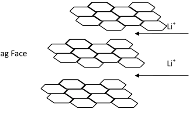
The basic building block of carbons is a planar sheet of carbon atoms conjugated by sp2 bond, the structure are shown as Fig. 2-3 (called graphene or basal plane). Each planar sheet is held up by van der Waal forces and is stacked in ordered or disordered to form crystallites. As lithium ions intercalate into the graphene layers, the layer structure changes and the structure are resilient enough for lithium ions to insert or deinsert. Then, the graphite served as a host structure for lithium ions intercalation.
Figure 2-3. The faces of graphite crystallite.
The graphene crystallite has two different edge sites: armchair and zigzag sites. While charging, the lithium ions must travel to the outer edges of the graphene sheet before coming to rest (intercalating) between the sheets. At the edge sites, the reactivity is much higher than at the basal plane. Thus, physical and chemical properties of carbon change with the ratio of basal-plane to edge-plane area.
Carbonaceous anode materials used in rechargeable lithium battery can be categorized into graphite, non- graphitized glass-like carbon (hard carbon) and graphitic carbon (soft carbon) [12].
Graphitic carbon is one of the most commonly used anode materials in commercialize. Graphite has the advantages of low cost and high columbic efficiency. The theoretical specific capacity of graphite is 372 mAh/g [13, 14].
During intercalation process, the Lithium ion intercalates into graphite, and Li+
Li+
Armchair Face Zigzag Face
then it forms LiC6 intercalation compound. That means every six carbon atoms can host only one lithium ion. Thus, graphite shows poor relatively low specific capacity.
Hard carbons can be used with Consumer electronics, such as personal computers. They can be prepared by a thermal decomposition of petroleum pitch. Generally, hard carbons show higher capacities than graphite, which had reversible specific capacities for lithium of up to 600mAh/g [15-17]. They are made up of small single layers. Therefore, the adsorption of lithium occurs on both sides of graphene sheets, which result in more than one absorption per six carbons and greater storage capacity. However, the voltage profile of hard carbon is mainly composed of two regimes, a sloped regime in a voltage range of 1.0–0.1 V. In this region, it only has capacity around 150–250mAh/g. The other one is a plateau region with a capacity around 100–400mAh/g [15-17].
Therefore, hard carbon materials have disadvantages such as low initial columbic efficiency and low tap density.
The soft carbons (graphitic carbon) basically comprise of sp2-hybridized carbon atoms. They are arranged in a planar “honeycomb-like” network, i.e., a
“graphene” layer is formed [18]. Van der Waals force provides a weak cohesion of the graphene layers, leading to the layered graphite structure. The carbon atoms are arranged hexagonally in a planar condensed ring system. The layers are stacked parallel to each other. The atoms within the rings are bonded covalently, whilst the layers are loosely bonded together by van der Waals forces. The high degree of anisotropy in graphite results from the two types of bonding acting in different crystallographic directions.
2.2-2 Si Anode
Silicon anode materials have attracted much attention in recent years due to its high theoretical capacity, low-voltage reaction plateau, low cost and environmental friendliness. It has high theoretical capacity of 4200 mAh/g, which is ten times of commercial graphite (372 mAh/g).
However, achieving this capacity is difficult at ambient temperature [19].
At ambient temperature, Dahn’s and Obrovac’s did detailed examination of the crystal structure. Their results proved that the fully lithiated phase of silicon at room temperature is Li15Si4, not Li22Si5, which shows maximum capacity of 3579 mAh/g-silicon [20-21]. Fig. 2-4 and Table 2-1 show typical binary Li-Si phase diagram and its corresponding crystallography data [22]. The results of Rietveld refinement of Li15Si4 are listed in table 2-2 with a space group of I 4 3d (cubic).
Silicon could act as anode materials in lithium-ion batteries to enhance capacity of battery (~3500 mAh/g with the formation of Li15Si4). However, Silicon anode suffers from volume expansion during cycling. Upon insertion and extraction of lithium, the volume expands to 400% of the initial size. This is almost highest volume expansions among the common alloy anodes. The huge expansion causes the crack of silicon, irreversible capacity of the first cycle, decrease of conductivity and capacity significantly during subsequent cycles. These reasons hinder the application of silicon anode on lithium ion rechargeable battery.
For example, Ryu et al. showed that commercial bulk silicon powder consists of 10 um particles as anode materials, and the first discharge capacity (lithiation) was about 3260 mAh/g [23]. However, the first cycle coulombic efficiency was only 35%. The specific capacity of 1170 mAh/g was obtained during the first charge (de-lithiation). The drastic capacity loss was observed in the subsequent cycles. After 10 cycles, the capacity dropped to lower than 200 mAh/g, which is insufficient for an anodes material.
To solve crack of silicon during cycling, much effort has been devoted. In order to increase the performance and cyclability of silicon materials, some research focus on nano-sized silicon. Synthesized nano-scaled morphology silicon and/or form silicon/carbon composite are one of the effective methods.
For example, Peng, KQ et al. proposed silicon nanowire arrays prepared by metal-induced chemical etching. The nanowire has not only good conductivity but also nanometer-scale rough surfaces. These two features facilitate charge transport and insertion/extraction of Li ions. The electroless-etched SiNWs anode showed higher charge capacity and longer cycling stability than the conventional Si wafer [24].
For example, Guo, H et al. proposed Silicon thin films deposited on rough Cu foil by a radio frequency magnetron sputtering. The thin thicknesses are in range 1000-5300 angstrom. They found that the stability and reversible discharge capacity are depend on the film thickness, and thinner ones have larger accommodation capacity. A Si film with 3120 angstrom provides a
reversible specific capacity over 3500 mA h/g with excellent cycleability under 0.5 C charge/discharge rates [25].
Figure 2-4. Li-Si phase diagram [26].
Table 2-1. Li-Si crystallography data [26].
Phase Composition (wt.% Si) Pearson symbol Space group Li
0 cI2 Fm3m
Li*
0 hp2 F63/mmc
L22Si5 47.9 cF432 F23
Li13Si4 55.4 oP24 Pbam
Li7Si3 63 hR7 R3m
Li12Si7 70.2 oP152 Pnma
Si 100 cF8 Fd3m
Questionable phases
Li4Si 50 oP250 ?
Li7Si2 53.6 oP36 Pbam
Li10Si3 54.9 cF416 ?
Li2Si 66.9 mC12 C2/m
Li13Si7 69 oP160 Pnma
* below -193 oC
Table 2-2. Results of the Rietveld refinement of Li15Si4.
Parameters Dahn et al. [26] Obrovac and Christensen [27]
Lattice constant 10.777 Å 10.685 Å
Si (16c) (x,y,z) Li (48e) Li (12a)
(0.462,0.462,0.462) (0.130,0.177,0.865) (0.375,0.0,0.250)
(0.459,0.459,0.459) (0.118,0.156,0.961) (0.375,0.0,0.250)
2.2-3. Silicon/Carbon Composite Anode
During charge, Organic solvents easily decompose on the negative electrodes. When appropriate organic solvents are used as the electrolyte, the solvent decomposes on initial charging and forms a solid layer called the solid electrolyte interphase (SEI) [28]. The SEI layer is electrically insulating and it usually provides ionic conductivity. It prevents further decomposition of the electrolyte during charge. However, as silicon anode suffers dramatic volume changes on cycling, the SEI layer will be broken on expansion.
Carbon coating or composite with silicon can help to reduce the SEI film formation and irreversible capacity. As mentioned, Carbon has less surface area than nano-silicon, thus side reactions in electrode and electrolyte take place less.
Besides, carbon possesses good electronic conductivity and it buffers huge volume expansion of silicon during lithiation and de-lithiation processes.
Therefore, in recent years, more research have focus on fabricate Si/C composites.
For example, Dan Thien, N., et al. proposed a carbon fiber-interwoven amorphous nano-SiOx/graphene structure [29]. They prepared a simple and facile room temperature synthesis of amorphous SiOx nanoparticles using silica, followed by their homogeneous dispersion with graphene nanosheets and carbon fibers in room temperature aqueous solution. Transmission and scanning electron microscopic(TEM and SEM) imaging reveal that amorphous SiOx primary nanoparticles are 20-30 nm in diameter and carbon fibers are
interwoven throughout the secondary particles of 200-300 nm, connecting SiOx nanoparticles and graphene nanosheets. This carbon fiber-interwoven nano-SiO0.37/graphene electrode exhibit good cycling performance and rate-capability under 5C rate. After over 50 cycles, the discharge capacities is still 1579-1263 mAh/g at the C/5 rate. It has capacity retention of 80% and Coulombic efficiencies of 99% and nearly sustained microstructure.
For example, Holzapfel, M et al. proposed two types of nano-size silicon prepared via thermal vapour deposition either with or without a graphite substrate are presented [30]. They showed superior reversible charge capacity and cycle life when it served as negative electrode. Then the lithiation reaction was applied on the materials. Raman spectroscopy, dilatometry and differential electrochemical mass spectrometry (DEMS) was used to investigate the materials. The Si/graphite compound material shows relatively high kinetics upon discharge, and the result showed relative volume change and low gas evolution of the nano silicon based electrode.
Many efforts have made on the research of Silicon/Carbon Composite anode materials. Table 2-3 lists some review recent paper proposed in 2013.
Table 2-3. Papers of Si/C composites anode material proposed in 2013 [31-47].
Paper title Description
Preparation and Characterisation of Silicon/Carbon Nanotube Composite Electrodes for Li-Ion Battery Systems [31].
Silicon powders and different amounts of multiwalled carbon nanotube were mechanically alloyed in polyacrynitrile solution via high speed planetary ball milling. Produced composite was characterised via X-ray diffraction pattern, scanning electron microscopy, energy dispersive spectroscopy and thermogravimetric analysis.
Si/graphene composite prepared by magnesium thermal reduction of SiO2 as anode material for lithium-ion batteries [32].
Nanosized Si/graphene composite was prepared by magnesium thermal reduction of the in-situ generated SiO2 particles on graphene sheets, in which about 5 nm-silicon nanopartides were homogeneously loaded on graphene sheets. This unique structure can not only accommodate the large volume changes, but also maintain electronic conductivity during Li-ion insertion/extraction. The composite exhibits an excellent cycling stability with a capacity of 1374 mAh/g over 120 cycles.
Synthesis and Lithium Storage Performance of Porous Silicon/Carbon Composite Material from SiCl4 [33].
Porous silicon/carbon composite was prepared via a mechanochemical reaction between Li13Si4 and SiCl4 under ball milling. Specific surface area of the composite can be adjusted by controlling the particle size distribution of Li13Si4.
The results indicated that the composite material exhibited a considerably high reversible capacity of 1 900 mAh/g and an excellent cycling stability with only 7.6%
capacity decay after 50 cycles at a current density of 300 mA/g.
Silicon nanoparticles supported on graphitic carbon paper as a hybrid anode for Li-ion
rechargeable batteries [34].
A hybrid anode consisting of silicon nanoparticles supported on a woven graphitic carbon paper is reported.
The silicon in the hybrid electrode exhibits a specific capacity of similar to 1300 mAh/g which decreases as the loading increases to 0.6 mg, but still showing good cyclability. The structural and morphological changes of graphite and silicon within the hybrid electrode during charge and discharge are also presented.
Silicon Oxycarbides in Hard-Carbon
Microstructures and Their Electrochemical Lithium Storage [35].
Silicon oxycarbide (Si-O-C) glasses have been obtained by pyrolysis of powdery blends, composed of polysiloxane resin and phenol aralkyl resin, to 1000 degrees C. Electrochemical measurements showed that delithiation capacities linearly increased to >800 mAh/g with increasing the silicon content in these Si-O-C glasses. Interestingly, the carbon-rich Si-O-C glasses had delithiation capacities of up to 580 mAh/g with good cyclability. Li-7 NMR analyzes indicated that the carbon-rich Si-O-C glasses have more hard carbon-like features and that at least two electrochemically active sites store lithium species.
Cross-Linked
Poly(acrylic acid) with Polycarbodiimide as Advanced Binder for Si/Graphite Composite Negative Electrodes in Li-ion rechargeable batteries [36].
Cross-linked poly(acrylic acid) (PAA) with polycarbodiimide (PCD) is utilized as a binder for the Si/graphite composite electrode. Cross-linkage of PAA can be modulated by the addition of the PCD as a cross-linker into the slurry. Initial reversible capacity of Si/graphite composite electrodes is increased with suppressed electrolyte decomposition by the use of cross-linked PAA. The Si-composite electrode with optimal amount of 1 wt% PCD cross-linker delivers more than 1,000 mAh/g of reversible capacity with improved capacity retention.
Caramel Popcorn Shaped Silicon Particle with Carbon Coating as a High Performance Anode Material for Li-ion
rechargeable batteries [37].
Caramel popcorn shaped porous silicon particles with carbon coating are fabricated by a set of simple chemical methods as active 'anode material.
Si particles are 'etched to form a porous structure, which provide space for the volume expansion and liquid electrolyte diffusion. A layer of amorphous carbon is formed inside the pores, which gives an excellent isolation between the Si particle and electrolyte, so that the formation of the SEI layer is stabilized. This novel structure enhances the mechanical properties of the Si particles, and the crack phenomenon caused by the volume change is significantly restrained. Therefore, an excellent cycle life is achieved.
Mesoporous, Si/C composite anode for Li battery obtained by 'magnesium-thermal' reduction process [38].
Mesoporous silicon was synthesized by a 'one spot' magnesium-driven reduction reaction from SBA-15 mesoporous silica template. Then, carbon coated in order to confer it electronic conduction. Mesoporous Si/C composite material showed an initial discharge capacity of about 1500 mAh/g at 0.1 C (=420 mA/g), which tend at a plateau at around 600 mAh/g after 100 cycles with an excellent coulombic efficiency.
Improving
microstructure of
silicon/carbon nanofiber composites as a Li battery anode [39].
Silicon/carbon nanofiber (Si/CNF) nanocomposite material as a anode for rechargeable lithium ion batteries was investigated. Amorphous silicon layers were uniformly coated via chemical vapor deposition on both the exterior and interior surfaces of the CNF.
The resulting Si/CNF composites exhibited capacities near 800 mAh/g for 100 cycles. Based upon the experimental analysis and theoretical calculation, they have proposed several interfacial engineering approaches to improve the performance of the electrodes by optimizing the microstructure of this nanocomposite.
Silicon-conductive nanopaper for Li-ion rechargeable batteries [40].
In this study, flexible and conductive nanopaper aerogels with incorporated carbon nanotubes (CNT) was fabricated. Such conductive nanopaper is made from aqueous dispersions with dispersed CNT and cellulose nanofibers, followed by deposition of a thin-layer of silicon through a plasma-enhanced CVD (PECVD) method. The open channels allow for an excellent ion accessibility to the surface of silicon.
A stable capacity of 1200 mA h/g for 100 cycles in half-cells is achieved. Such flexible anodes based on earth abundant materials and aqueous dispersions could potentially open new opportunities for low-cost energy devices.
In Situ Synthesis and Cell Performance of a Si/C
Core-Shell/Ball-Milled Graphite Composite for Lithium Ion Batteries [41].
A high-capacity silicon-carbon core shell (Si/C) supported by ball-milled graphite (BMG) was synthesized in situ using a hydrosilylation reaction.
The Si/C/BMG sample effectively absorbed high volumetric expansion/contraction generated. After 50 charge/discharge cycles, the Si/C/BMG electrodes still had a very high capacity of 1615 mAh/g.
Lithium insertion into carbon-rich SiOC ceramics: Influence of pyrolysis temperature on electrochemical
properties [42].
Carbon-rich silicon oxycarbide ceramics (SiOC) was prepared via thermal conversion of polyorganosiloxane.
The ceramics demonstrate high lithiation capacity and reliable rate capability when used as anode material in Li-ion rechargeable batteries.
A high-performance lithium-ion battery anode based on the core-shell heterostructure of silicon-coated vertically aligned carbon
nanofibers [43].
A high-performance hybrid lithium-ion anode material using coaxially coated silicon shells on vertically aligned carbon nanofiber (VACNF) cores was reported. The unique "cup-stacking" graphitic microstructure makes VACNFs a good lithium-ion intercalation medium and, more importantly, a robust bush-like conductive core to effectively connect high-capacity silicon shells for lithium-ion storage. A high specific capacity of 3000-3650 mAh/g, comparable to the maximum value of amorphous silicon, has been achieved. About 89% of the capacity is retained after 100 charge-discharge cycles at the C/1 rate.
Nano silicon carbide: a new lithium-insertion anode material on the horizon [44].
Cubic (3C polytype) nano SiC was prepared by a chemical vapour deposition (CVD) method. It delivers a reversible lithium insertion capacity of about 1200 mAh/g over 200 cycles.
Facile conductive bridges formed between silicon nanoparticles inside hollow carbon nanofibers [45].
A simple method for improving the electrochemical performance of silicon nanoparticle-core/carbon-shell (Si-core/C-shell) nanofibers was reported. Additional conductive paths between the Si nanoparticles were formed by incorporating a small percentage of multi-walled carbon nanotubes (MWNTs)into the Si nanoparticle core. The electrical conductivity of a single Si-core/C-shell nanofiber showed a more than five times increase according to MWNT addition. A galvanostatic
charge-discharge test demonstrated that a small amount of MWNTs greatly improved the electrochemical performance of the Si-core/C-shell nanofibers due to the enhanced participation of Si through the additional conductive paths formed between the Si nanoparticles.
Electrochemical Behavior's of
Diamond-Like-Carbon-C oated Silicon
Monoxide-Graphite Composite Anode for Li-Ion Battery [46].
Effects of a diamond-like carbon (DLC) coating on a silicon monoxide-graphite composite electrode are studied in order to improve the electrochemical characteristics of silicon monoxide anodes. The discharge capacity of the coated cell is 523 mAh/g at the first cycle and 409 mAh/g at the 100th cycle at a 0.5 C rate. The 100-cycle capacity retention is 78.2%, which is greater than that of the bare cell (52%).
Highly robust silicon nanowire/graphene core-shell electrodes without polymeric binders [47].
low cost approach to fabricate hybrid silicon nanowire (SiNW)/graphene nanostructures was reported. It exhibit enhanced cycle performance with the capability of retaining more than 90% of their initial capacity after 50 cycles. They also demonstrate the use of hot-pressing in the absence of any common polymer binder such as PVDF to bind the hybrid structure to the current collector.
Chapter 3 Experimental
3.1 Chemicals
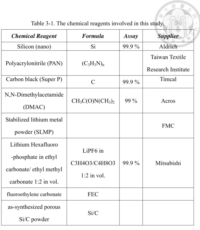
All chemical reagents used in this study are listed in Table 3-1. Moreover, all the reagents in this study were of laboratory reagent grade and were used as received without any further purification. The deionized water used in all the experiments was purified by a reverse-osmosis system (Purelab Maxima/ELGA), of which the resistivity is 18.2 MΩ-cm.
Table 3-1. The chemical reagents involved in this study.
Chemical Reagent Formula Assay Supplier
Silicon (nano) Si 99.9 % Aldrich
Polyacrylonitrile (PAN) (C3H3N)n
Taiwan Textile Research Institute
Carbon black (Super P) C 99.9 % Timcal
N,N-Dimethylacetamide
(DMAC) CH3C(O)N(CH3)2 99 % Acros Stabilized lithium metal
powder (SLMP) FMC
Lithium Hexafluoro -phosphate in ethyl carbonate/ ethyl methyl
carbonate 1:2 in vol.
LiPF6 in C3H4O3/C4H8O3
1:2 in vol.
99.9 % Mitsubishi
fluoroethylene carbonate FEC
as-synthesized porous
Si/C powder Si/C
3.2 Synthesis of Anode Materials
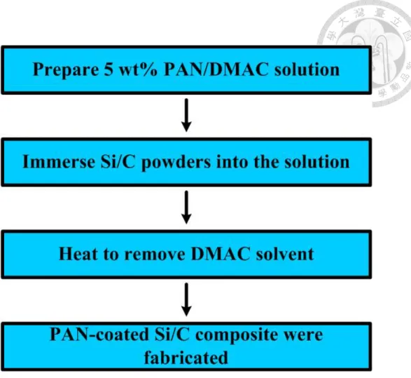
3.2-1 Preparation of PAN-coated Si/C Composites
We use solution coating method to coat porous Si/C composites with a thin Polyacrylonitrile (PAN) layer. Polyacrylonitrile (PAN) powders were dissolved in the solvent of DMAC to prepare 5 wt% PAN solution. The as-synthesized porous Si/C powders were immersed in the 5 wt% PAN solution and then ultrasonically treated for 24 hours to form a well-dispersing-mixture.
Then the obtained solution was heated to 180 ℃ to remove solvent and coating process was complete. The weight ratio of PAN to Si/C composite in the solution is kept at 3% and 5% respectively. Figure 3.1 displays the experimental flowchart of coating Si/C composites with PAN.
Figure 3-1. Experimental flowchart of fabrication of PAN-coated Si/C.
3.2-2 Electrode and Coin Cell Assembled
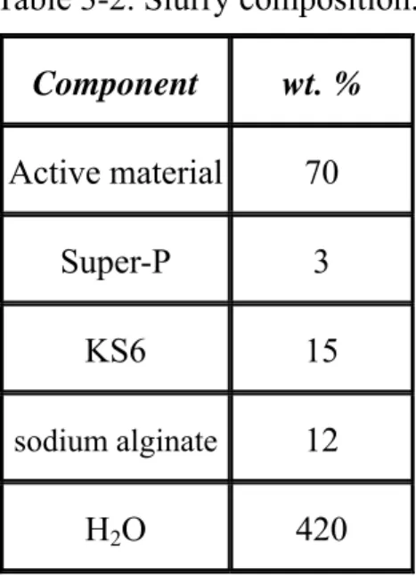
The Si-based electrodes constitute, on the dry basis, 70 wt% active material, 3 wt% nano-sized carbon black (Super P) and 15 wt% KS6 as conductive additives. 12 wt% Sodium alginate was added as the binder. The slurry composition of Si-based electrodes is listed in Table 3-2.
Table 3-2. Slurry composition.
Component wt. %
Active material 70
Super-P 3 KS6 15 sodium alginate 12
H2O 420
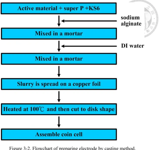
Figure 3.2 shows the flowchart of preparing Si/C electrode. First, the active material was well mixed with super P and KS6 in the mortar. Following, the binder sodium alginate was added to the mixture, and the mixture were mix in the mortar until they were blend uniformly. Then mix de-ionized water with the mixture to form slurry. The slurry was spread uniformly on a thin copper foil with thickness of 50 μm by using a continuous coater. Then the electrode was heated at 100 ℃ to evaporate the solvent. The electrode was cut to a disk shape with the diameter of 13 mm. The disk-shape electrode was put inside a
vacuum oven to be heated for 6 hours at 150 ℃ before assembling the coin cell.
CR2032 coin cells were fabricated from Si-based electrodes. Lithium foil was the counter electrode. We used two commercial electrolytes. One was 1M LiPF6 in ethylene carbonate (EC)/ethyl methyl carbonate (EMC) (vol % of 1:2).
Another one is EC/EMC (vol % of 1:2) with 10 vol% fluoroethylene carbonate (FEC) as additive. All the potentials reported herein are referenced to Li/Li+. A typical schematic drawing of CR2032 coin cell is shown in Figure 3.3.
Figure 3-2. Flowchart of preparing electrode by casting method.
Figure 3-3. Schematic drawing of a coin cell.
3.2-3 Preparation of PAN film Composites
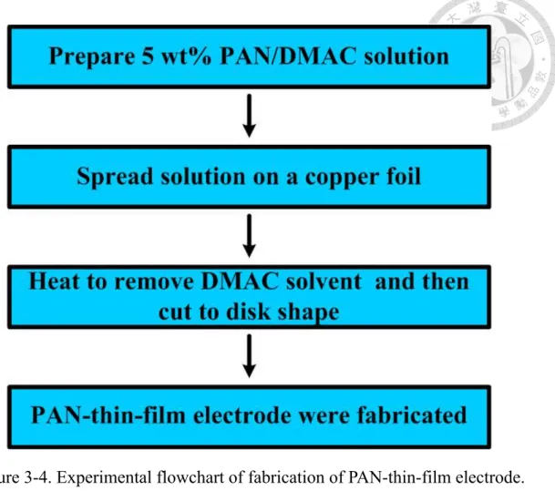
In order to understand the effect of PAN film on Si/C electrode, we use solution coating method to fabricate a PAN-thin-film electrode. First, Polyacrylonitrile (PAN) powders were dissolved in the solvent of DMAC to prepare a 5 wt% PAN solution. The solution was spread uniformly on a thin copper foil with thickness of 30 μm by using a continuous coater. After spreading, the electrode was heated at 180 ℃ to evaporate the solvent. Then the electrode was cut to a disk shape with the diameter of 13 mm. Finally, the disk-shape electrode was put inside a vacuum oven to be heated for 6 hours at 150 ℃ before assembling the coin cell. Figure 3.4 displays the experimental flowchart of fabricating a PAN-thin-film electrode
.
Figure 3-4. Experimental flowchart of fabrication of PAN-thin-film electrode.
3.2-4 Pre-lithiation Approach for Porous Si/C Composite
A simple Pre-lithiation approach was carried out by adding stabilized lithium metal powder (SLMP) on the electrode before assembling the coin cell. First, SLMP was sprayed on the disk-shape electrode. Then, electrolyte was first wetted in 3 drops of electrolyte. After the addition of SLMP and electrolyte, the electrode was immediately taken to assemble the coin cell. All the processes mentioned above were implemented in the drying room.
3.3 Electrochemical Characterization
3.3-1 Charge and Discharge Strategies
In this study, we used the following charge-discharge strategies to access electrochemical characterization.
The procedure is divided into two parts. In the first part (Process A), we run the cell at different cycle rate. In the first two cycles, we run the cell at 50mA/g(0.05C) to let the cell formation. After, run it at 0.1C for 5 cycles, 0.2C.
Then run it 0.5C, 1C, 2C, and 5C respectively for 3 cycles.
In the second part (Process B), we run the cell at 0.5C first, and then run the cell to 0.3V to test its impedance. After testing impedance, we charge the cell and then run cycle at 0.5C for 30 cycles. After 30 cycles, we repeat the second part again. Figure 3.5 displays the experimental flowchart of running cycles
.
Figure 3-5. Experimental flowchart of running cycles.
3.3-2 Electrochemical Impedance Spectroscopy
Electrochemical impedance spectroscopy (EIS) is a powerful tool for examining many chemical and physical processes. It is also an experimental method of characterizing electrochemical systems. It is a useful technique with application in many fields, such as corrosion, battery, fuel cell, and sensor development.
While the simple concept of electrical resistance which obeys Ohm’s law is well-known, however, the real world contains elements exhibiting much more complex behavior. The EIS technique measures impedance of a system over a range of frequencies, and therefore the frequency response of the system, including the energy storage and dissipation properties, is revealed. In this study, data obtained by EIS is expressed graphically in a Nyquist plot.
Here, each coin-cell was consecutively charged or discharged to different levels, at which impedance spectra were taken. The cell was allowed to equilibrate for 30 min before each spectrum was taken. An AUTOLAB frequency response analyzer (AUTOLAB, Eco Chenie PGSTAT30) was employed for obtaining the spectra by applying a sine wave of 10 mV amplitude within the frequency range from 1 mHz to 100 kHz.
Chapter 4 Results and Discussions
4.1 Si/C Composites Electrode
Our research is based on Si/C composite; therefore, it is essential to measure its properties first. The following sections are to discuss the characterizations and the cycle performance of Si/C composite.
Cycle test and electrochemical impedance spectroscopy (EIS) were applied. All the experiments were done under room temperature and atmosphere pressure.
Before running the cell, we run the cell at 0.3C to calculate its capacity.
The cell has 1458 mAh/g discharge capacity and 1130mAh/g charge capacity.
And first cycle coulombic efficiency was 77.5%.
The cycling data of the Si/C composite electrodes are displayed in 4-1(a)-(b). Fig. 4-2 show the coulombic efficiency versus cycle. The calculated capacities are solely based on the active materials, porous Si/C particles in the electrode. In process A, as the figure shows, Si/C composite has 1412mAh/g charge capacity and 1100 mAh/g discharge capacity at first cycle under 0.05C rate. The coulombic efficiency was 77.8%. At third cycle under 0.1C rate, the composite showed 1105mah/g discharge capacity and 96.3% coulombic efficiency. As the rate increased, the capacity decreased. The composite showed
304mAh/g at 5C rate (20 cycle).
Coulombic efficiencies below 100% are experienced by both electrolytic and galvanic cells when electrons or ions participate in unwanted side reactions.
These losses appear as heat and/or chemical byproducts. coulombic efficiencies below 100% reflect the thermodynamic irreversibility of every real-world chemical reaction. For Si/C lithium rechargeable batteries, irreversible capacities during the initial cycles may be ascribed to the SEI formation, arising from the decomposition of electrolyte, and the insertion of Li ions trapped inside silicon particles or amorphous carbon.
In Process A, as cycle rate increased, the coulombic efficiency increased.
We could see that between 3 to 11 cycle (0.1C, 0.2C), the coulombic efficiency was about 98%. In contract, the coulombic efficiency was more than 99%
between 12 to 22 cycle (rate = 1C, 2C 5C). This might be due to irreversible side reaction between lithium ions and the electrode. Under low cycle rate, the lithium ions stayed longer, thus the reaction sites offers more chance to trap lithium ions during the lithiaiton process. In Process B, Si/C composite showed 525 mAh/g at first (23th cycle). After two repeats (88th cycle), discharge capacity was 404 mAh/g, and 77.7% capacity was retained. Coulombic efficiency was about 98.5% between 23th to 40th cycles. But after 40th cycles, the coulombic efficiency was randomly between 95 to 100%. This might be due to pulverization of Si/C electrode.
Electrochemical impedance spectroscopy (EIS) experiments were carried out for Si/C electrodes in the beginning and after each repeat of Process B.
Fig. 4-3 shows the Nyquist plots of this measurements. Generally, the impedance attributed to the formation of SEI films in the high-frequency range is quite small than that caused by charge-transfer in the intermediate-frequency range. Therefore, the high-frequency semicircle is corresponded to formation of SEI film and/or contact resistance. The diameter of semicircle observed in Fig.
4-22 is mainly dominated by charge-transfer resistance on electrode/electrolyte interface. The inclined line following semicircle in the low-frequency range is related to the Li-ion diffusion process within electrodes.
As can be seen, the diameter of semicircle of Si/C electrode was decreased by 64.4% (from 37.2 to 13.6 Ohm) while the slope of inclined line did not change obviously.
Figure 4-1. Cycle tests for electrodes of Si/C: (a) cycle Process A (b) cycle process B.
Figure 4-2. Coulombic efficiency versus cycle for electrodes of Si/C.
Figure 4-3. Nyquist plots for electrodes of Si/C .
4.2 PAN-coated Si/C Composites Electrode
Although the cycle performance of Si/C electrodes was indeed enhanced compared to pure Si, the improvement was still limited. Thus, we modified the surface of Si/C material by coating of thin-film PAN. The material and electrochemical characterizations of this PAN-coated Si/C composite will be discussed in the following sections.
The cycling data of PAN-coated Si/C composite electrodes are displayed in Fig. 4-4(a)-(b) and the Coulombic efficiency data in Fig. 4-5. As the figure shows, PAN-coated Si/C composite has 1934mAh/g charge capacity and 1412 discharge capacity, respectively. The coulombic efficiency at first cycle under 0.05C rate was 76.4%. The coulombic efficiency reached >96.5% after third cycles. At third cycle under 0.1C rate, the composite showed 1423mah/g discharge capacity and 96.3% coulombic efficiency. As the rate increased, the capacity decreased. The composite showed 405mAh/g at 5C rate (20 cycle).
We can see some interest characteristics of PAN-coated electrode. First, the overall capacity was increased by about 30% after coating 3%wt PAN. This is due to functional groups of PAN thin film. PAN contains amidoxime groups, which can be used for the treatment of metals because of the polymers’
complex-forming capabilities with metal ions. Second, first cycle coulombic efficiency of PAN-coated electrode was 76.4%. Compared to uncoated sample, the coulombic efficiency was decreased by 1.5%.
In process A, as cycle rate increased, the coulombic efficiency also
increased as uncoated electrode. We could see that between 3 to 11 cycle (0.1C, 0.2C), the coulombic efficiency was about 98%. Then, the coulombic efficiency was more than 99% between 12 to 22 cycle (rate = 1C, 2C 5C).
Coulombic efficiency data was almost the same with uncoated Si/C electrode, but 0.2~0.5% lower than Si/C uncoated electrode. In process B, the composite showed 686mah/g in the beginning at 0.5C (23th cycle). After two repeats (88th cycle), 548 mAh/g (79.8% capacity) was retained. In contrast with uncoated Si/C, we can see coulombic efficiency was kept at about 97% after 23th cycles.
As can be seen in Fig.4-6, the diameter of semicircle of Si/C electrode was decreased by 66.0% (from 56.1 to 19.1 Ohm). The slope was also unchanged.
We can see that impedance of PAN-coated Si/C was higher than uncoated Si/C, which is due to relatively low conductivity of PAN thin film, but it did not affect diffusion resistance of Lithium-ions within electrodes.
Figure 4-4. Cycle tests for electrodes of Si/C and 3%PAN-coated Si/C: (a) cycle Process A (b) cycle process B.
Figure 4-5. Coulombic efficiency versus cycle for electrodes of Si/C and 3%PAN-coated Si/C.
Figure 4-6. Nyquist plots for electrodes of Si/C and 3%PAN-coated Si/C.
(Solid symbols: after 1th cycle; open symbols: after 30th cycles.)
4.3 Characterizations of PAN-coated Si/C Composites FEC/EC/EMC electrolye
Fig. 4-7(a)-(b) show the characteristics of PAN-coated Si/C composites after adding 10vol % of FEC into the electrolyte. Besides, 3wt% PAN-coated Si/C, 5wt% PAN-coated Si/C, and Si/C without coating are used as electrode material in this process.
For process A, we can see some interest characteristics. First, cycle data showed that coating of PAN would enhance 30% capacity either in electrolyte with or without FEC. Second, compared 3% PAN-coated data with 5%PAN coated data, capacity did not enhanced after we increased amount of coating.
Then, after additive of 10%FEC, cycle capacities were decreased, especially at high scan rate. At 3rd cycle (0.1C), 3% PAN-coated Si/C showed 1371 mAh/g in EC/EMC electrolye and 1211 mAh/g in FEC/EC/EMC electrolyte. Capacity was lowered by 11.7%. At higher scan rate (20th cycle, 5C), it showed 403 mAh/g in EC/EMC electrolye and only 176 mAh/g in FEC/EC/EMC electrolye.
Capacity loss was 56.3% after adding of FEC.
For process B, 5%PAN-coated Si/C did not show more capacity than 3%PAN-coated Si/C, and both of them gave 30% capacities higher than uncoated Si/C. As seen in fig.7(b), capacities of Si/C electrode after additive of FEC in electrolyte were higher than in EC/EMC electrolyte, And we can see cycle performance in process B after additive of FEC became more stable. For 3%PAN-coated Si/C in FEC-added electrolyte, it showed 640 mAh/g and 571
mAh/g in 4th cycle and 67th cycle respectively. There were 10.8% capacity loss during 66 cycles. While 3%PAN-coated Si/C in EC/EMC electrolyte, it showed 706 mAh/g and 547 mAh/g in 4th cycle and 67th cycle respectively. Only 77.5%
capacity was retained after 66 times of cycling. We can see that additive of FEC would decrease capacities of Si/C electrode, but additive of FEC electrolyte provide stable cycle performance.
Fig.4-8 showed coulombic efficiency data. In Process A, coulombic efficiency of PAN-coated Si/C and uncoated Si/C with FEC additive in electrolyte reached 99% after 15th cycle (1C), which showed little difference with EC/EMC electrolyte. In process B, we can see that coulombic efficiencies were kept between 98.5% and 99.0%, after additive of FEC in electrolyte. This is due to that fluoroethylene carbonate in electrolyte can act as an SEI modification additive, hence, the cycle performance and coulombic efficiency were enhanced.
Fig.4-9 showed Nyquist plots for Si/C in FEC-added electrolyte.
For uncoated Si/C, the diameter of semicircle of Si/C electrode was increased by 40.0% (from 45.0 to 63.2 Ohm) while the diameter of semicircle of 3%
PAN-coated Si/C was increased by 45.0% (from 46.7 to 67.7 Ohm).
The slope of inclined line did not change obviously, which means both coating of PAN and additive of VE did not affect diffusion resistance of Lithium-ions within electrodes.
Figure 4-7. Cycle tests for Si/C electrodes for different amount of PAN coating and different electrolyte: (a) cycle Process A (b) cycle process B.
Figure 4-8. Coulombic efficiency versus cycle for Si/C electrodes for different amount of PAN coating in FEC-added electrolyte.
Figure 4-9. Nyquist plots for Si/C electrodes for different amount of PAN coating in FEC-added electrolyte.
4.4 Pre-lithiation Approach
In the previous section, coating of PAN and adding FEC into electrolyte indeed improved the overall coulombic efficiency for Si/C composites electrode.
However, the coulombic efficiency of first cycle remains to be enhanced (only
~75%) in order to meet the practical needs. In this section, the pre-lithiation approach was adopted to conquer this problem. It is believed that for
carbon-contained anodes, some lithium ions are trapped inside the sites of carbon during first insertion process and are not released upon extraction process, thus causing the loss of reversible capacity. Therefore, we put some lithium to occupy these sites before conducting the discharge-charge processes, hoping to improve the coulombic efficiency of first cycle. Herein, the stabilized lithium metal powders (SLMP) were chosen in instead of lithium metal due to that SLMP are more stable in the normal condition. The amount of SLMP added was based on that of lithium which is required to compensate the capacity loss due to the carbon in the composites. The cycle test for electrode with pre-lithiation approach is shown in Fig.4-10. It can be seen that the coulombic efficiency of first cycle was enhanced to, indicating that the
pre-lithiation approach is certainly effective. Moreover, pre-lithiation approach was also beneficial to increase the coulombic efficiency for the following cycles. Therefore, with the use of pre-lithiation approach, the coulombic efficiency for each cycle could be improved to 99.9%.
Figure 4-10. Coulombic efficiency versus cycle for pre-lithiated 3%PAN-coated Si/C electrodes in FEC-added electrolyte.
Chapter 5 Conclusion
In this study, we used as synthesized Si/C powders as anode material, to construct lithium ion rechargeable secondary batteries. Subsequent treatments, PAN-coating, addition of FEC in electrolyte, and pre-lithiation were taken to enhance electrochemical characteristics of Si/C composite electrode.
For Si/C composite electrode, cycle life and coulombic efficiency were improved compared to commercial silicon powder. For cycle Process B in our study, Si/C composite electrode retained 77.7% capacity after 60 cycles, and coulombic efficiency was more than 95% after 60 cycles. However, the improvement of cycle life for Si/C electrode was limited to some extent because of the accumulation of SEI layers during cycling.
After coating of PAN, specific capacity was enhanced by 30%. The
enhancement was due to amidoxime groups of PAN, which can be used for the treatment of metals because of the polymers’ complex-forming capabilities with lithium ions. For first cycle coulombic efficiency, it was lowered by 1.5%
compared to uncoated Si/C composite electrode, which is due to unwanted reaction between lithium ions and PAN film. After 60 cycles, 79.8% capacity was retained and coulombic efficiency was kept at about 97%. These results showed good enhancement after coating of PAN on Si/C composite electrode.
Then, we added FEC to EC/ EMC electrolyte to enhance cycle
performance of PAN-coated Si/C electrode. Capacities were lowered after using FEC/EC/EMC electrolyte before 20 cycles, but specific capacities were enhanced after cycling. 89.2% capacity was retained after 60 times of cycling, and coulombic efficiency was enhanced to ~98.5%
The pre-lithiation approach was also adopted to enhance the coulombic efficiency in the first cycle. The electrode with the use of pre-lithiation approach displays the improved efficiency of ~99.9% in the first cycle.
Moreover, the coulombic efficiency in the following cycles maintains at
~99.9%. This result indicates that pre-lithiation approach is effective and has potentially practical use for increasing overall coulombic efficiency.
References
1. J. M. Tarascon and M. Armand, "Issues and challenges facing rechargeable lithium batteries." Nature, 414, 359-367 (2001).
2. G. A. Nazri and G. Pistoia, LITHIUM BATTERIES - Science and Technology Kluwer Academic Publishers, Massachusetts, USA.
(2004).
3. Whittingham M. S., "Electrical Energy Storage and Intercalation Chemistry." Science, 192 (4244), 1126–1127. (1976).
4. Besenhard, J.O. and Fritz, H.P., "Cathodic Reduction of Graphite in Organic Solutions of Alkali and NR4+ Salts." J. Electroanal. Chem., 53 (2), 329. (1974).
5. Besenhard, J. O., "The electrochemical preparation and properties of ionic alkali metal-and NR4- graphite intercalation compounds in organic electrolytes." Carbon, 14 (2), 111–115. (1976).
6. Schöllhorn, R.; Kuhlmann, R.; Besenhard, J. O., "Topotactic redox reactions and ion exchange of layered MoO3 bronzes." Materials Research Bulletin, 11, 83. (1976).
7. Besenhard, J. O.; Schöllhorn, R., "The discharge reaction mechanism of the MoO3 electrode in organic electrolytes." Journal of Power Sources, 1 (3), 267. (1976).
8. USPTO search for inventions by. Goodenough, John. Patft.uspto.gov.
Retrieved 8 October 2011.
9. E. Plichta, M. Salomon, S. Slane, M. Uchiyama, D. Chua, W. B. Ebner and H. W. Lin, "A rechargeable Li/LixCoO2 Cell." Journal of Power Sources, 21, 25-31. (1987).
10. N. N. Greenwood and A. Earnshaw, Chemistry of the Element 2nd ed.Butterworth, UK. (1997).
11. J. E. Huheey, E. A. Keiter and R. L. Keiter, Inorganic Chemistry:
Principles of Structure and Reactivity 4th ed.HarperCollins, New York, USA. (1993).
12. M. Yoshio, H. Wang, K. Fukuda, T. Umeno, T. Abe and Z. Ogumi,
"Improvement of natural graphite as a lithium-ion battery anode material, from raw flake to carbon-coated sphere." Journal of Materials Chemistry, 14, 1754-1758. (2004).
13. J. Yamaura, Y. Ozaki, A. Morita, A. J. Ohta, J., Power Sources, 43, 233.
(1993).
14. A. Mabuchi, Tanso, 165, 298. (1994).
15. J. R. Dahn, T. Zheng, Y. H. Liu, J. S. Xue, Science, 270, 590. (1995).
16. H. Azuma, H. Imoto, S. Yamada, K. Sekai, J., Power Sources, 81, 1.
(1999).
17. J. L. Tirado, Mater., Sci. Eng. R, 40, 103. (2003).
18. B. McEnaney, Carbon Materials for Advanced Technologies T. D.
Burchell, Ed.Pergamon, Elesevier, Amsterdam (1999).
19. W. J. Weydanz, M. Wohlfahrt-Mehrens and R. A. Huggins, "A Room Temperature Study of the Binary Lithium–Silicon and the Ternary
Lithium–Chromium–Silicon System for Use in Rechargeable Lithium Batteries." Journal of Power Sources, 81-82, 237-242. (1999).
20. T. D. Hatchard and J. R. Dahn, "In Situ XRD and Electrochemical Study of the Reaciton of Lithium with Amorphous Silicon." Journal of The Electrochemical Society, 151, A838-A842. (2004).
21. M. N. Obrovac and Leif Christensen, "Structural Changes in Silicon Anodes during Lithium Insertion/Extraction." Electrochemical and Solid-State Letters, 7, A93-A96. (2004).
22. Binary Alloy Phase Diagrams 2nd ed. Plus Updates, Windows version, ASM International, Materials Park, OH (1996).
23. Ryu, J.H.; Kim, J.W.; Sung, Y.-E.; Oh, S.M., "Failure modes of silicon powder negative electrode in lithium secondary batteries." Electrochem.
Solid-State Lett., 7, A306–A309. (2004)
24. Peng, K.Q. ; Jie, J.S. ; Zhang, W.J., "Silicon nanowires for rechargeable lithium-ion battery anodes." Applied Physics Lett., 7.
(2008).
25. Guo, H. ; Zhao, H.L. ; Yin, C.L. ; Qiu, W.H., "A nanosized silicon thin film as high capacity anode material for Li-ion rechargeable batteries."
Material Science and Engineering B-Solid State for Advanced Technology., 7, 173-176. (2006).
26. Binary Alloy Phase Diagrams 2nd ed. Plus Updates, Windows version, ASM International, Materials Park, OH. (1996).
27. T. D. Hatchard and J. R. Dahn, "In Situ XRD and Electrochemical Study of the Reaciton of Lithium with Amorphous Silicon." Journal of The Electrochemical Society, 151, A838-A842. (2004).
28. Balbuena, P.B., Wang, Y.X. (eds) Lithium Ion Batteries: Solid Electrolyte Interphase Imperial College Press, London, ISBN 1860943624. (2004).
29. Dan Thien, N., et al., "Facile Synthesis and High Anode Performance of Carbon Fiber-Interwoven Amorphous Nano-SiOx/Graphene for Rechargeable Lithium Batteries." Acs Applied Materials & Interfaces, 5 (21), 11234-11239.
30. Holzapfel, M. ; Buqa, H. ; Hardwick, L.J. ; Hahn, M. ; Wursig, A. ; Scheifele, W. ; Novak, P. ; Kotz, R. ; Veit, C. ; Petrat, F.M., "Nano silicon for lithium-ion batteries." Electrochimica Acta., 11, 973-978.
(2006).
31. Cetinkaya, T., et al., "Preparation and Characterisation of Silicon/Carbon Nanotube Composite Electrodes for Li-Ion Battery Systems." Acta Physica Polonica A, 123 (2), 398-400. (2013).
32. Du, Y., et al., "Si/graphene composite prepared by magnesium thermal reduction of SiO2 as anode material for lithium-ion batteries."
Electrochemistry Communications, 36, 107-110. (2013).
33. Feng, X.-J., et al., "Synthesis and Lithium Storage Performance of Porous Silicon/Carbon Composite Material from SiCl4." Chinese Journal of Inorganic Chemistry, 29 (11) 2289-2296. (2013).
34. Fu, Y. and A., "Manthiram Silicon nanoparticles supported on graphitic carbon paper as a hybrid anode for Li-ion batteries." Nano Energy, 2 (6), 1107-1112. (2013).
35. Fukui, H., et al., "Silicon Oxycarbides in Hard-Carbon Microstructures and Their Electrochemical Lithium Storage." Journal of the Electrochemical Society, 160 (8), A1276-A1281. (2013).
36. Han, Z.-J., et al., "Cross-Linked Poly(acrylic acid) with Polycarbodiimide as Advanced Binder for Si/Graphite Composite Negative Electrodes in Li-Ion Batteries." Ecs Electrochemistry Letters, 2 (2), A17-A20. (2013).
37. He, M., et al., "Caramel Popcorn Shaped Silicon Particle with Carbon Coating as a High Performance Anode Material for Li-Ion Batteries."
Acs Applied Materials & Interfaces, 5 (21), 11152-11158. (2013).
38. Hong, I., et al. Mesoporous, "Si/C composite anode for Li battery obtained by 'magnesium-thermal' reduction process." Solid State Ionics, 232, 24-28. (2013).
39. Howe, J. Y., et al., "Improving microstructure of silicon/carbon nanofiber composites as a Li battery anode." Journal of Power Sources, 221, 455-461. (2013).
40. Hu, L., et al., "Silicon-conductive nanopaper for Li-ion batteries." Nano Energy, 2 (1), 138-145. (2013).
41. Jung, D.-W., et al., "In Situ Synthesis and Cell Performance of a Si/C Core-Shell/Ball-Milled Graphite Composite for Lithium Ion Batteries."
Journal of Nanoscience and Nanotechnology, 13 (12), 7855-7859.
(2013).
42. Kaspar, J., et al., "Lithium insertion into carbon-rich SiOC ceramics:
Influence of pyrolysis temperature on electrochemical properties."
Journal of Power Sources, 244, 450-455. (2013).
43. Klankowski, S. A., et al., "A high-performance lithium-ion battery anode based on the core-shell heterostructure of silicon-coated vertically aligned carbon nanofibers." Journal of Materials Chemistry A, 1 (4), 1055-1064. (2013).
44. Kumari, T. S. D., et al., "Nano silicon carbide: a new lithium-insertion anode material on the horizon." Rsc Advances, 3 (35), 15028-15034.
(2013).
45. Lee, B.-S., et al., "Facile conductive bridges formed between silicon nanoparticles inside hollow carbon nanofibers." Nanoscale, 5 (11), 4790-4796. (2013).
46. Lee, J. K., et al., "Electrochemical Behavior's of Diamond-Like-Carbon-Coated Silicon Monoxide-Graphite Composite Anode for Li-Ion Battery." Journal of the Electrochemical Society, 160 (9), A1348-A1352. (2013).
47. Lee, S. E., et al., "Highly robust silicon nanowire/graphene core-shell electrodes without polymeric binders." Nanoscale, 5 (19), 8986-8991.
(2013).
![Figure 2-1. Comparison of the gravimetric and volumetric energy densities of various rechareable batteries system [1]](https://thumb-ap.123doks.com/thumbv2/9libinfo/9606760.632705/15.892.149.735.583.1050/figure-comparison-gravimetric-volumetric-densities-various-rechareable-batteries.webp)
![Figure 2-2. Schematic illustration of the charge/discharge process in a lithium-ion cell consisting of lithium insertion compounds as both anode and cathode [2]](https://thumb-ap.123doks.com/thumbv2/9libinfo/9606760.632705/17.892.189.785.99.476/figure-schematic-illustration-discharge-process-consisting-insertion-compounds.webp)
![Figure 2-4. Li-Si phase diagram [26].](https://thumb-ap.123doks.com/thumbv2/9libinfo/9606760.632705/23.892.158.784.125.637/figure-li-si-phase-diagram.webp)
![Table 2-1. Li-Si crystallography data [26].](https://thumb-ap.123doks.com/thumbv2/9libinfo/9606760.632705/24.892.126.781.113.801/table-li-si-crystallography-data.webp)