國立臺灣大學工學院應用力學研究所 碩士論文
Institute of Applied Mechanics College of Engineering
National Taiwan University Master Thesis
超常材料在不同組成率下之負折射和後退波之研究 Investigation of negative refraction and backward wave in meta-material based on different constitutive relations
張博涵 Po-Han Chang
指導教授:舒貽忠 博士 陳瑞琳 博士 Advisor: Yi-Chung Shu, Ph.D.
Ruey-Lin Chern, Ph.D 中華民國 101 年 7 月
July, 2012
i
致謝
時光飛逝,碩士兩年生涯即將結束。想起兩年前從一個對研究完全不懂得新手 到現在可以獨力完成論文。這都要感謝一路幫助我的老師和同學。有你們的指導 與討論,才能使我在研究上能有所精進。
首先感謝父母的養育之恩,在這麼多年求學生涯中提供給我那麼多的資源與支 持讓我無後顧之憂地專心念書與研究。每當遇到困難,你們都會給予我最大支持 與鼓勵。並讓我知道,不論發生什麼事,家裡大門總是為我而開。
感謝我的指導老師: 陳瑞琳教授及 舒貽忠教授。感謝陳老師的細心教導,其 嚴謹的研究態度與討論方式不只讓我在研究上受益良多,也讓我學到待人處事所 必備之態度。感謝舒老師在數學教學上給我的啟發,在本論文中一些數值傅立葉 積分的方法即是老師課堂上所學的。沒有這方面的知識,學生在研究上肯定不會 如此順利。也感謝百忙中抽空來擔任學生口試委員的海大光電系 張瑞麟教授以 及中研院應科所 郭志禹老師。你們的糾正不只使本論文更加完備也提供了我更 多元的觀點來思考研究盲點。
感謝實驗室 426 每一位成員。感謝百廷、維懿,和你們討論中幫助我更了解許 多基本電磁相關知識。感謝起平、宏志、秉憲學長,和你們請教過程中讓我更能 掌握研究上的思路與分析。感謝羽軒、英智、毅桓,和你們研究上互相討論與激 勵總能幫我度過難關。感謝永承、宏仁,和你們相處兩年來讓我的研究所生活更 加豐富。感謝學弟們:翊豪、泓安、宗緯,彥儒,凱陽,惠安,你們的提醒發問 讓我觀念更加確立並刺激更多研究心得。
最後感謝女友侃庭這幾年來的陪伴。感謝你這一年來支持我研究並習慣以實驗 室為家的日子。每當研究有瓶頸時,你總是鼓勵我並幫我轉移注意力。每當研究 有突破時,你總是第一個為我歡呼。在進入人生下一個階段前,我也要和你說聲:
謝謝。
要感謝的人太多了,感謝所有曾經幫助與關心我的人。在這邊我要致上最大的 感謝與祝福。
ii
中文摘要
人工超常材料雍有自然界天然材料所沒有之電磁行為。這些特殊現象導致了
新的物理機制與工程應用。以物理角度而言,我們可用一等效材料參數來表示。
一旦等效參數確立,即可代入組成率方程式並研究其波傳行為。
本論文即已組成率為基礎下探討不一樣之波傳行為。由馬克斯威方程式,我
們解析推導出色散關係、共振模態、阻抗與波因廷向量。之後考慮單一介面之波 傳問題並利用模態解出反射與穿透係數。其中,針對其中一種非等效性材料:假 對掌性材料做波傳研究。本研究發現到在假對掌性材料中波傳模態為兩個橢圓偏 振且這兩個不同橢圓模態可分別導致負折射與後退波。最後並用數值高斯光束模 擬來驗證此現象。
關鍵字: 超常材料、負折射、後退波、假對掌性材料、非等向性材料
iii
Abstract
Meta-materials are man-made structures which exhibit unusual electromagnetic response. Such extraordinary responses give rise to new physical insights and engineered applications. The most common way to describe this kind of material is by defining effective material parameters connected to constitutive relations. Once constitutive relations are obtained, the wave propagating properties could be explored through basic electromagnetic theory.
In this thesis we investigate wave propagation based on different sets of constitutive relations. Dispersion relation, eigenwaves, impedance together with Poynting vector are derived. Also we derive reflection and transmission coefficients through a single planer interface. In particular, we study plane wave propagation in a special kind of bi-anisotropic medium: pseudochiral medium. It is found that two elliptic eigenwaves appear in pseudochiral material and allow us to realize negative refraction or backward wave. Finally, Gaussian beam propagation is conducted to verify our results.
Keywords: Meta-material, Negative refraction, Backward wave, Pseudo-chiral medium, Anisotropic complex medium.
iv
Contents
致謝 i
中文摘要 ii
Abstract iii
Chapter 1 Introduction ... 1
Chapter 2 Constitutive Relations ... 2
2.1 Constitutive equations ... 2
2.2 Lossless, reciprocal medium ... 3
Chapter 3 Anisotropy medium ... 4
3.1 Dispersion relation ... 4
3.2 Eigenmodes solution ... 5
3.3 Impedance analogy ... 5
3.4 Poynting vector ... 6
3.5 Reflection and transmission in inhomogeneous media ... 6
3.6 Negative refraction and backward wave ... 8
3.7 Slab problem ... 9
3.7.1 Layered media ... 9
3.7.2 Effective medium for periodic grating structure ... 10
Chapter 4 Chiral medium ... 13
4.1 Dispersion relation ... 13
4.2 Eigenmodes solution ... 13
4.3 Impedance analogy ... 14
4.4 Poynting vector ... 15
4.5 Reflection and transmission in inhomogeneous media ... 15
4.6 Negative refraction... 19
Chapter 5 Bi-anisotropic medium ... 23
5.1 Anisotropic dielectric medium ... 23
v
5.1.1 Dispersion relations ... 23
5.1.2 Eigenmode solutions ... 24
5.1.3 Admittance analogy ... 24
5.1.4 Reflection and transmission in layered media ... 25
5.2 Uniaxially omega medium ... 26
5.2.1 Dispersion relation ... 27
5.2.2 Eigenmode solutions ... 27
5.2.3 Impedance analogy ... 28
5.2.4 Poynting vector ... 28
5.2.5 Reflection and transmission in layered media ... 29
5.3 Uniaxial chiral medium... 30
5.3.1 Dispersion relations ... 30
5.3.2 Eigenmode solutions ... 31
5.3.3 Admittance analogy ... 31
5.3.4 Poynting vector ... 32
5.3.5 Reflection and transmission in layered media ... 32
5.4 Pseudochiral material ... 34
5.4.1 Dispersion relation ... 34
5.4.2 Eigenmode solutions ... 36
5.4.3 Admittance analogy ... 36
5.4.4 Poynting vector ... 37
5.4.5 Reflection and transmission in layered media ... 37
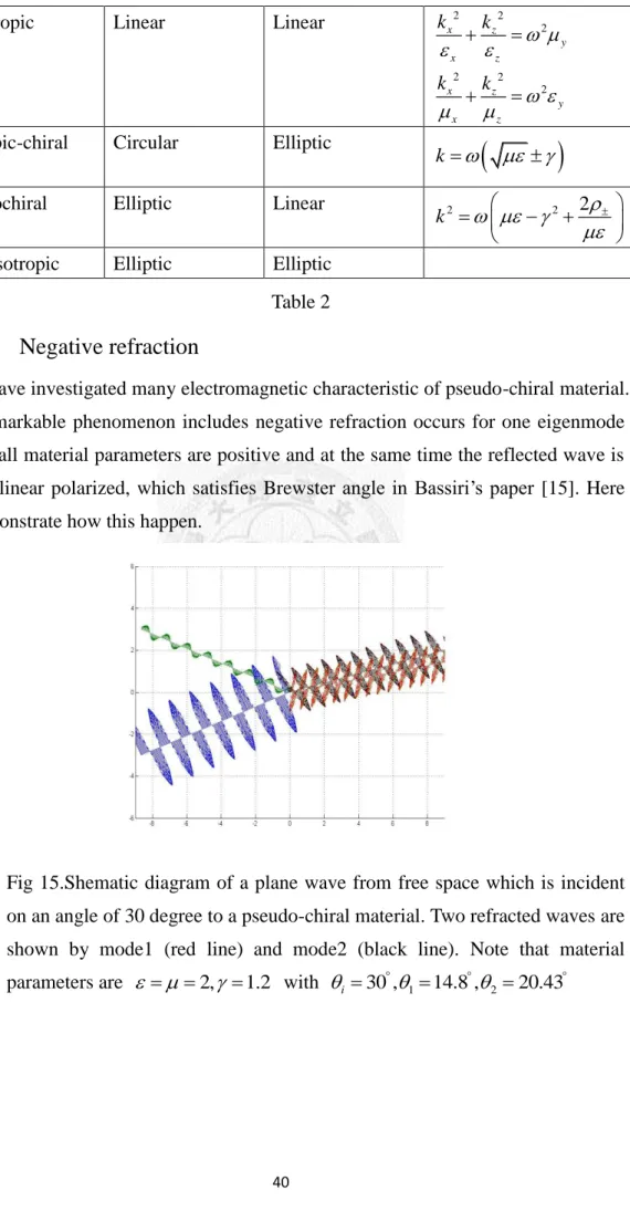
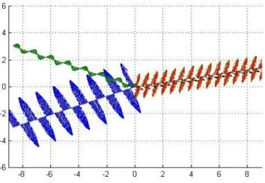
5.4.6 Negative refraction... 40
5.4.7 Conditions of negative refraction and backward wave ... 43
Chapter 6 Gaussian Beam wave ... 46
6.1 Beam propagation through dielectric interface ... 46
6.2 Beam propagation through chiral interface ... 49
vi
6.3 Beam propagation through pseudochiral interface ... 51 Chapter 7 Conclusion... 54
Reference 55
1
Chapter 1 Introduction
Artificial meta-material having simultaneously negative parameters has drawn enormous attention since the first experimental fabrication by Smith [1] in 2000. The theoretical study of such medium was first presented by Veselago in 1967 and the term left-handed material was used to describe this kind of material. Significant physical phenomena and applications include negative refraction [2], backward wave [3], negative Goos-Hanchen shift [4], and the realization of perfect lens [5]. In 2004, Pendry shows that negative refraction could also be realized by isotropic chiral material [6] and its potential applications are then investigated by many researchers [7-9]. More recently, many more complex bi-anisotropic materials are widely theoretical studied to verify the possibility of negative refraction and backward wave [10-14].
Plane wave propagation through inhomogeneous media have long been an important topics in electromagnetic. Bassiri [15] dealt with reflection and transmission coefficients (R,T) of chiral medium in 1988. Later Tretyakov [16]
studied R,T for general bi-anisotropic medium using transmission line theory. It is seen that impedance or admittance play crucial role in R T formulations.
In the present thesis, we study harmonic plane wave propagation in various complex media by scalar wave function with time conventionexp(i t). Dispersion relations, eigenwave, impedance as well as Poynting vector are clearly derived for each case. Reflection and transmission coefficients through inhomogeneous media are also derived analytically and relations to negative refraction or backward waves are discussed. We present a general formula with obvious physical insight and compare with the existing works. Furthermore, we investigate the wave propagation properties in pseudochiral material, in which wave characteristics may differ from those we have known in other bi-anisotropic media. Finally, Gaussian beam propagation simulations are also demonstrated to easily clarify the phenomenon of negative refraction.
2
Chapter 2 Constitutive Relations
2.1 Constitutive equations
Effects of wave propagation through a linear, isotropic and homogenous medium have been widely studied based on Maxwell equation. Basic remarks include the wave vector, electric field and magnetic field are perpendicular to each other and form a right-handed system; dispersion relation relates the material’s dielectric or magnetic susceptibility so that the index of refraction could be defined to estimate the wave velocity. Many materials, however, are anisotropic in nature. Anisotropy is taken into consideration by assuming different behaviors in each direction, in which the physical quantity produced is no longer constant but depends upon the direction. Another characteristic electromagnetic property is the cross effect or chirality, in which the electric and magnetic flux are influenced by magnetic and electric field. These two significant phenomena destroy the symmetry of constitutive relations and in general, could be written as:
D E H
B H E
(2.1) where are dielectric and magnetic tensors and , are responsible for cross coupling. The term bi-anisotropy is used to describe materials with chiral property.
Note that constitutive relations could be expressed by other forms. Eq. (2.1) is called Condon-Tellegen relation. However, in different problems, the same name is given to parameters which are not exactly the same. Another form of constitutive relations are given by Post, Jaggard and Mickelson [17], which reads
1
D E B
H B E
(2.2) Another relations focusing on the nonlocal behavior is given by Drude, which are called Drude-Born-Fedorov relations by Lakhtakia.
D E E H
B H H E
(2.3)
One of the relations is adopted depending on which electric and magnetic quantities are used. However, different sets of relations could be related to each other and the results are given by Sihvola and Lindell [18]. Throughout this thesis, we use Condon-Tellegen relation Eq.(2.1) to analyze our problem.
3
2.2 Lossless, reciprocal medium
Restricting ourselves to lossless media, from conservation of energy we see that dielectric and magnetic tensors must be symmetric. Lossless implies there is no absorption during wave propagation and that every tensor element is real. According to coordinate transformation, every real symmetric matrix could be diagonalized as the form
0 0
0 0
0 0
0 0
0 0
0 0
x y
z
x y
z
(2.4)
The above coordinate axis is referred to principal coordinate axis, which means that all off-diagonal elements are zero. Let us consider chiral medium. Chirality structure is often encountered in biochemistry. Assuming lossless and reciprocity still hold, from conservation of energy we must have
T (2.5)
* (2.6)
which means that must be an imaginary number.
4
Chapter 3 Anisotropy medium
3.1 Dispersion relation
Confine ourselves to anisotropy medium but ignore the cross coupling effect due to chirality. Most materials possess certain degree of anisotropy and could be broadly categorized in terms of: cubic, uniaxial and biaxial as listed in Table 1
Cubic Uniaxial Biaxial
Principal axis
0 0
0 0
0 0
0 0
0 0
0 0
x x
z
0 0
0 0
0 0
x y
z
Material Diamond Quartz Mica
Table 1
In general, from Eqs. (2.1)&(2.4), constitutive equations have the form:
0 0
0 0
0 0
x y
z
D E (3.1)
0 0
0 0
0 0
x y
z
B H (3.2)
Insert (5) (6) into Maxwell equations. The following eigenvalue equation is obtained:
1
[(p I ) (p I ) ] E 0 (3.3) / 1/ ( sin k x kcos z)
p k e e
where denotes angle of wave vector to z axis.
For nontrivial E, the determinant of the bracket must be zero, which gives two dispersion relations.
2 2
x z 2
y
z x
k k
(3.4)
2 2 0 2 2
s i n c o s s i n c o s
x z y x z y
x z x z
k k
(3.5)
5
where k02 2 0 0 and
2 2
x z 2
y
z x
k k
(3.6)
2 2 0 2 2
s i n c o s s i n c o s
x z y x z y
x z x z
k k
(3.7)
From above derivation two wave numbers could be obtained and both of them depend not only on the medium parameters but on propagation direction. To examine our results, simply set
x y z and
x y z such that two wave numbers are identical and is not a function of propagation direction, which is an isotropic medium and confirm with elementary electromagnetic theory.3.2 Eigenmodes solution
Via dispersion relation two wave numbers have been found in term of . However, further derivations show that it is easier to express wave number in way of k because x it is assumed that k is a known quantity in later problems. Let us rewrite wave x numbers and solve eigenvalue problem for Eq.(3.3). Physically, the corresponding eigenvectors indicate the modes.
From (3.4)
2
x z y x x
z
z
p p
(3.8)
( 1 , 0 , x x )
z z
E p
p
E (3.9) From (3.6)
2
x z y x x
z
z
p p
(3.10)
(0,1, 0)
E
E (3.11)
3.3 Impedance analogy
Once electric polarized mode is known, Maxwell equations give the relation between magnetic field and electric field. Transverse impedance is defined as the ratio of transverse electric field to magnetic field.
6
1 1 1 1 1
( )
H B k E k I E (3.12) For TM mode (1, 0, z z)
x x
E p
p
E
2 x 2
z x
x z z x z
y o
y z y
p p
E k E k
H E
p
(3.13)
2 /
x y x x z
TM x z
y x x
E p p
H
(3.14)
For TE mode EE(0,1, 0)
2 /
x y x x z z
x
x x
p p
H
(3.15)
x z
z
H p
y
TE x
x z
E
H p
(3.16)
3.4 Poynting vector
Time average Poynting vector indicate the direction of energy flow and is significant when considering plane wave refraction in inhomogeneous media.
TM mode from Eq.(3.9)
2 x
z x
y
z z
x
k
S H
S k
S (3.17)
TE mode from Eq.(3.11)
2 x
z x
z z
x
k
S E
S k
S (3.18)
3.5 Reflection and transmission in inhomogeneous media
Wave vector, dispersion relations, impedance and poynting vectors are derived to solve reflection and refraction problem with inhomogeneous media. Consider a plane wave from a dielectric material entering an anisotropic medium as follow in Fig 1:
7
Fig 1
The incident electric and magnetic field could be written as
cos sin
im x z ie y
E E
Ei e e e (3.19)
0 0
/ / ( cos sin )
im y ie x z
E E
Hi e e e (3.20)
where Eim and E refer to the magnitude of TM and TE incidence respectively. ie Impedance 0 is defined with respect to incident medium. Similarly, the reflected electric and magnetic field could be written as
(cos sin )
rm x z re y
E E
Er e e e (3.21)
0 0
/ / (cos sin )
rm y re x z
E E
Hr e e e (3.22)
To find the reflection and transmission coefficients Ermand E it is assumed that re the refracted modes are unity in magnitude so that R and T could be regarded directly as the amplitude ratio with respect to incidence field. Therefore, transmitted electric and magnetic fields are expressed as
( x x )
te y tm x z
z z
E E p
p
Et e e e (3.23)
( )
te tm
x z y
TE TM
E E
A
Ht e e e (3.24)
where
2 /
x y x x z
TM
x
p
and
2 /
TE x
x y px x z
denote TE and TM
modes impedance respectively.
Now apply Maxwell boundary condition to obtain reflection and refraction coefficients.
8
0 0
0
c o s c o s 2 c o s
c o s
TM
rm TM im
TM
tm TM im
E E
E E
(3.25)
0 0
0
cos cos
2 cos
cos
TE
re TE ie
TE
te TE ie
E E
E E
(3.26)
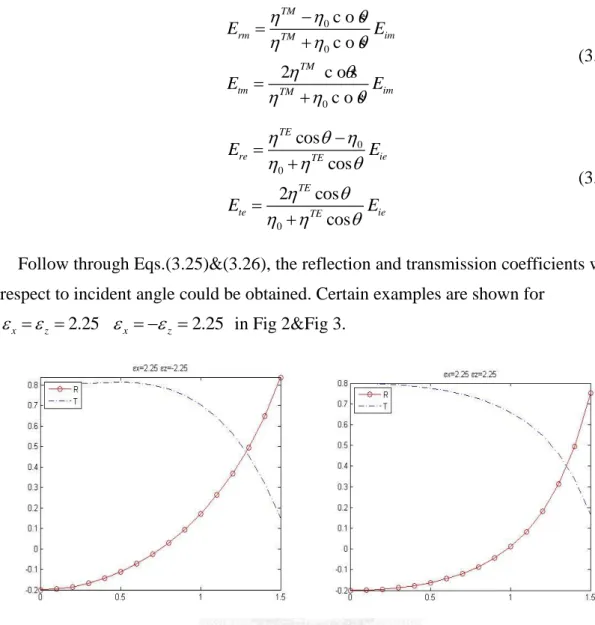
Follow through Eqs.(3.25)&(3.26), the reflection and transmission coefficients with respect to incident angle could be obtained. Certain examples are shown for
x z 2.25
x z 2.25 in Fig 2&Fig 3.
Fig 2 Fig 3
3.6 Negative refraction and backward wave
Many interesting phenomenon emerge when electromagnetic waves incident from a dielectric material to an anisotropic medium. Two of which are negative refraction and backward wave. The definitions of negative refraction and backward wave have been given elsewhere [3]. In brief, negative refraction could be defined when the wave vector in the transmitted medium has an opposite direction with respect to the wave vector along interfacial direction and a plane wave is said to be backward wave if the wave vector has a negative projection onto the Poynting vector. Now suppose permittivity and permeability tensor are along principal axis as defined by Eq.(2.4) and could be negative. Reflection and transmission coefficients, however, could not totally obey Eqs.(3.25)& (3.26) due to the choice of sign of wave vector k in Eq.(3.4) z or (3.6) and need to be derived in terms of incidence wave vector k . Detailed i
9
derivations and physical insight have been studied by I.V.Lindell, S.A.Tretyakov et,al [3] and P.A.Belov [14]. The following shows result for case with x2.25
z 2.25
in Fig 4.
Fig 4
3.7 Slab problem
3.7.1 Layered media
Layered media with multiple interfaces have been an important issue in electromagnetic due to its wide range of application. One of which is to determine the reflection and refraction coefficients and then retrieve material properties by inverse scattering technique. Consider a plane wave normally incident upon a layered structure ABC. Following the method used in[19],the expressions for the fields could be written as
In medium A: (z<-d)
1
1
1
1
( )
( )
( )
( )
1
1
ik z d
i i
ik z d
i i
A ik z d
r r
ik z d
r r
A
E E e x
H E e y
E E e x
H E e y
(3.27)
In medium B: (-d<z<0)
2 2
2 2
1
ik z ik z
B Bt Br
ik z ik z
B Bt Br
B
E E e E e x
H E e E e y
(3.28)
In medium C: (z>0)
10
3
1 3
ik d
C t
ik d
C t
C
E E e x
H E e y
(3.29)
where the wave component EBtand EBr in medium B are forward and backward wave respectively. Using Maxwell’s boundary conditions requiring tangential components of electric and magnetic fields be continuous at two interfaces, we have At z=-d
2 2
2 2
( )
1 1
ik d ik d
i r Bt Br
ik d ik d
i r Bt Br
A B
E E E e E e
E E E e E e
(3.30)
At z=0
1 1
Bt Br t
Bt Br t
B C
E E E
E E E
(3.31)
Solve four unknowns based on four equations, we get
2
2
2
2
2
2 1 3 2 2 1 3 2
2
2 1 3 2 2 1 3 2
2 3
2
2 1 3 2 2 1 3 2
2 2 3
2
2 1 3 2 2 1 3 2
2 2 3
2
2 1 3 2 2 1 3 2
( )
4
( )
( ) cos( ) ( ) sin( )
( )
( ) cos( ) ( ) sin(
ik d
r ik d
ik d
t ik d
Br
Bt
E e
e E e
e E i
i k d k d
E i
i k d k
d)
(3.32)
Although the above formulas are based on dielectric material, lossy medium is also applicable if impedance is in term of complex value. Our result can still be verified by transmission line theory.
3.7.2 Effective medium for periodic grating structure
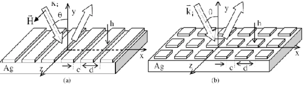
Consider a plane wave normally incident to a periodic grating structure with i 0 as below in Fig 5
11
Fig 5 Periodic grating structure in one (a) and two (b) dimensions. Substrate is silver and the coating film is silver-air array with height h and periodicity d.
Suppose the dimension of geometry structure is much smaller than the excitation wavelength. Such material is termed metamaterial and for one dimension periodicity, could be characterized as uniaxial anisotropic medium with effective longitudinal and transverse permeability.
/ /x
m a
y z m a
d
d c c
d c c
d d
(3.33)
where
m: permeability of silver
a: permeability of air.
We investigate the metamaterial absorption behavior with regard to wavelength of incident wave as well as height of the structure and check whether effective theory is valid. Let incident wavelength range from 300-1000nm and height from 0-1000nm.
We scan for absorption spectrum. Using Eq.(3.33) as layer B impedance, we demonstrate that the smaller periodicity d compared to wavelength, the better the effective medium in Fig 6 resemble real structure Fig 7.
(a) (b)
12
Fig 6 Absorption spectrum of effective medium using c=0.1d (a) and c=0.2d (b).
Note that effective material parameter only depend on volume fraction of air and silver, regardless of absolute value of d.
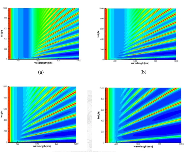
(a) (b)
(c) (d) Fig 7 Absorption spectrum of real structure with c=0.1d while d=10nm (a), d=50nm (b), d=100nm (c) and d=300nm (d).
13
Chapter 4 Chiral medium
4.1 Dispersion relation
Consider bi-isotropic chiral medium with cross coupling but ignore the effect of anisotropy. Isotropic implies the physical property doesn’t depend on direction.
Therefore, the material parameters in constitutive relations could be regarded as scalar quantities, which have the following forms
0 0 0 0
0 0 0 0
0 0 0 0
i i
i
D E H (4.1)
0 0 0 0
0 0 0 0
0 0 0 0
i i
i
B H E (4.1)
Follow the same procedure as in anisotropic case and assume wave vector lie on x-z plane. Using Eqs. (4.1) and (4.1) into Eq.(3.3), two wave vectors are given by
k1 (4.2)
k2 (4.3)
Note that the wave vectors in the isotropic chiral medium are not function of direction angle, which is quite different from anisotropy cases considered in the previous chapter. For nonchiral materials ( 0), the two propagation vectors coincide and become , which is well known in the elementary electromagnetic theory.
4.2 Eigenmodes solution
Once the eigenvalue is obtained, we could go for the eigenvector and determine the wave propagation modes in the material. Based on the results given by Eqs.(4.2)
&(4.3), two eigenvectors could be obtained.
For k1
1E(cos , , sin ) i
E (4.4)
For k2
14
2 E(cos , i, sin )
E (4.5)
From above derivation it can be easily seen that two circularly polarized wave serve as modes for corresponding two wave vectors. The speeds of right circular polarized mode (RHCP) and left circular polarized mode (LHCP) are different due to parameter . Note that TE and TM modes cannot be taken as eigenvectors in chiral medium, which is different from dielectric material.
4.3 Impedance analogy
Impedance could be obtained similar to Eq.(3.12). For bi-isotropic material, the results are even simpler.
1
0
0
z
x x z
y z x
k i
E k k
k I i
E k i E
H E AE (4.6)
Inserting Eqs.(4.4)&(4.5) into Eq.(4.6), impedance could be obtained.
For k1
(RHCP)
11
1
cos , , sin
i i i
E
H
1
(4.7)
For k1
(LHCP)
22
2
cos , , sin
i i i
E
H
2
(4.8)
Note that kx ksin , kz kcos in above derivation and two eigenmodes share the same impedance. This could be seen as the result of isotropic medium.
15
4.4 Poynting vector
Time-averaged Poynting vector is defined as 1 *
2Re
S E H
For k1
(RHCP)2 2
sin
( )
cos
x x
z z
x
S p
E E
S p
p
S (4.9)
For k2
(LHCP)2
sin cos
x z
S E
S
S (4.10)
Isotropic material shows that the direction of energy flow is the same as direction of wave vector, which means the energy and momentum flows are parallel.
4.5 Reflection and transmission in inhomogeneous media
Consider plane wave problem in inhomogeneous layered medium. An incident plane wave from isotropic medium causes reflection and transmission phenomenon when passing through the interface. Suppose an incident wave can be decomposed into TE and TM modes, which can be written as
cos sin
im i x i z ie y
E E
Ei e e e (4.11)
0 0
( cos sin )
im ie
y i x i z
E E
Hi e e e (4.12) where subscripts m and e refer to TM and TE incidence. Reflected wave, however, are not TE or TM wave as in the nonchiral case. Instead, the reflected wave need to be expressed as the elliptical wave form:
0
(cos sin )
1 ( (cos sin ))
r r y r i x i z
r r y r i x i z
E E
E E
E e e e
H e e e (4.13)
Transmitted waves are the linear combination of the two circularly polarized waves, which has the form:
16
1( cos 1 sin 1) 2( cos 2 sin 2)
ik z x ik z x
t tRe tLe
E E E (4.14)
where
1 1 1
2 2 2
(cos sin )
(cos sin )
t tR x z y
t tL x z y
E i
E i
E e e e
E e e e (4.15)
1
E and t E correspond to right and left circular wave respectively. Note that when t2 oblique incidence is taken into account, two polarized wave have different refracted angles due to different values of wave number. Here 1and 2denote refracted angles with respect to RHCP and LHCP. With impedance, magnetic field has the form
1( cos 1 sin 1) 2( cos 2 sin 2)
1 2
ik z x ik z x
t t t
i i
e e
Z Z
H E E (4.16)
where impedance Z
With Maxwell boundary condition, reflection and refracted coefficients could be obtained.
Reflection coefficients:
11 12
21 22
r i
r i
E R R E
E R R E
(4.17)
where
2 2 1 1 1 1 2 2
11 2 2 1 1 1 1 2 2
1 2
12 2 2 1 1 1 1 2 2
1 2
21 2 2 1
( )( ) ( )( )
( )( ) ( )( )
2 ( )
( )( ) ( )( )
2 ( )
( )(
Tm Tm Te Te Tm Tm Te Te
Tm Tm Te Te Tm Tm Te Te
Tm Tm Tm
Tm Tm Te Te Tm Tm Te Te
Tm Tm Tm
Tm Tm Te T
Z Z Z Z
R Z Z Z Z
i Z Z
R Z Z Z Z
i Z Z
R Z Z
1 1 1 2 2
2 2 1 1 1 1 2 2
22 2 2 1 1 1 1 2 2
1 2 1 2
1 2
1 2 1 2
0 0 1
) ( )( )
( )( ) ( )( )
( )( ) ( )( )
cos , cos , cos
cos , cos ,
e Tm Tm Te Te
Tm Tm Te Te Tm Tm Te Te
Tm Tm Te Te Tm Tm Te Te
Tm Tm Te Te
i
Tm Tm Te Te
i
Z Z
Z Z Z Z
R Z Z Z Z
where
Z Z Z Z Z Z Z
0cos2
(4.18)
Transmitted coefficients:
1 11 12
2 21 22
i t
i t
E
E T T
E T T E
(4.19)
17
2 2
11 2 2 1 1 1 1 2 2
2 2
12 2 2 1 1 1 1 2 2
1 1
21 2 2 1 1 1 1 2 2
22
2 ( )
( )( ) ( )( )
2 ( )
( )( ) ( )( )
2 ( )
( )( ) ( )( )
2
Te Tm Tm
Tm Tm Te Te Tm Tm Te Te
Te Te Te
Tm Tm Te Te Tm Tm Te Te
Te Tm Tm
Tm Tm Te Te Tm Tm Te Te
iZ Z
T Z Z Z Z
Z Z
T Z Z Z Z
iZ Z
T Z Z Z Z
T
2 2 1 (1 1 11) 1 2 2
( )( ) ( )( )
Te Te Te
Tm Tm Te Te Tm Tm Te Te
Z Z
Z Z Z Z
(4.20)
where
1 2 1 2
1 2
1 2 1 2
0 0 1 0 2
cos , cos , cos
cos , cos , cos
Tm Tm Te Te
i
Tm Tm Te Te
i
Z Z Z Z Z Z Z
Our results are identical to that given by Bassiri [15] using Post-Jaggard relations.
HereR12,R T T are cross polarizations due to the nature of the circular wave and 21, 12, 21 denominator in each coefficient could be viewed as TM TE coupling. In other words, because both circular waves could be seen as a linear combination of TE and TM wave with phase difference 90 degree, two circular eigenmodes appear and linear polarizations are no longer independent basis. However, physical meaning is obvious if we regard chiral materials as a generalization of isotropic material. Suppose 0, two wave vectors degenerate and only repeated mode exists. From Eqns.(4.18) and (4.20) we reproduce reflection and transmission formula, given by
11
12 21
22
( )
( )
0
( )
( )
Te Te
Te Te
Tm Tm
Tm Tm
R Z Z
R R
R Z Z
(4.21)
11
12
21
22
( )
( )
( )
( )
Te
Te Te
Te
Tm Tm
Te
Te Te
Te
Tm Tm
T iZ Z T Z
Z T iZ
Z T Z
Z
(4.22)
where ZTm Zcos ,t ZTeZcos , i Tm0cos , i Te0cost . Cross reflection coefficients vanish and transmitted coefficients are derived for circular modes. Note that in an isotropic medium, both linear and circular polarized modes could serve as
18
basis.
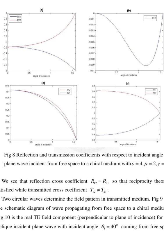
Reflection and transmission coefficients as function of incidence angle are plotted below in Fig 8 through (d) for case of free space entering chiral with parameters
4, 2, 0.5
Fig 8 Reflection and transmission coefficients with respect to incident angle of a plane wave incident from free space to a chiral medium with 4,2, 0.5
We see that reflection cross coefficient R12 R21 so that reciprocity theorem is satisfied while transmitted cross coefficient T12T21.
Two circular waves determine the field pattern in transmitted medium. Fig 9 shows the schematic diagram of wave propagating from free space to a chiral medium and Fig 10 is the real TE field component (perpendicular to plane of incidence) for an TE oblique incident plane wave with incident angle i 400 coming from free space to a chiral material with 2, 0.6.
Fig 9 (a) shows that the left hand space is the total field of incident and reflected wave while the two circular waves combine for the right hand space. For nonchiral case,
2, 0
, two eigenwaves degenerate and only one transmitted wave is
19
observed as expected from basic electromagnetic in Fig 9(b).
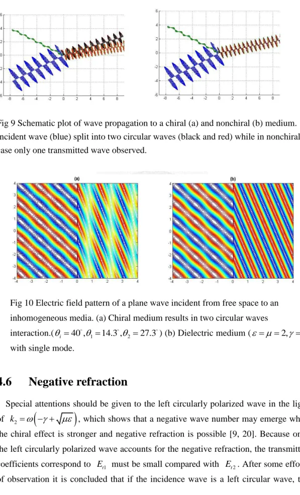
Fig 9 Schematic plot of wave propagation to a chiral (a) and nonchiral (b) medium.
Incident wave (blue) split into two circular waves (black and red) while in nonchiral case only one transmitted wave observed.
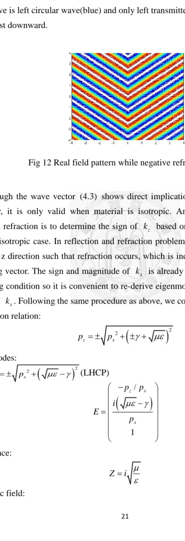
Fig 10 Electric field pattern of a plane wave incident from free space to an inhomogeneous media. (a) Chiral medium results in two circular waves
interaction.(i 40 ,114.3 ,2 27.3 ) (b) Dielectric medium ( 2, 0) with single mode.
4.6 Negative refraction
Special attentions should be given to the left circularly polarized wave in the light of k2
, which shows that a negative wave number may emerge when the chiral effect is stronger and negative refraction is possible [9, 20]. Because only the left circularly polarized wave accounts for the negative refraction, the transmitted coefficients correspond to E must be small compared with t1 E . After some efforts t2 of observation it is concluded that if the incidence wave is a left circular wave, the20
transmitted coefficients may vanish for the right circularly polarized wave in some special cases. We derive criteria as follow:
Suppose LHCP incidence wave:
cos sin
i EiL i xi y i z
E e e e (4.23)
0
(cos sin )
iL
i i x y i z
E i i
H e e e (4.24)
Refracted wave could be decomposed to RHCP and LHCP components:
cos sin
cos sin
r ErR i xi y i z ErL i xi y i z
E e e e e e e (4.25)
0 0
cos sin cos sin
r rR i x y i z rL i x y i z
i i
E i E i
H e e e e e e (4.26)
Transmitted wave in chiral medium has the same form as (4.14) and(4.15). By Maxwell boundary conditions reflection and transmission problem could be given based on LHCP incidence mode.
0 0 1 2
2 2 2
0 0 1 2 0 1 2
0 1 2
2 2 2
0 0 1 2 0 1 2
0 1
( )( ) ( )
2 2 ( ) ( )
2 ( )( )
2 2 ( ) ( )
2 ( ) (
i rR
i
i i
rL
i i
i tR
Z Z cos cos cos
E Z cos Z cos cos Z cos cos cos
Z cos cos cos cos
E Z cos Z cos cos Z cos cos cos
Z Z cos cos cos E
2 2 2 2
0 0 1 2 0 1 2
0 1
2 2 2
0 0 1 2 0 1 2
)
2 2 ( ) ( )
2 ( ) ( )
2 2 ( ) ( )
i i
i tL
i i
Z cos Z cos cos Z cos cos cos
Z Z cos cos cos
E Z cos Z cos cos Z cos cos cos
(4.27)
Special case is conducted for r r 1 and 2, it is seen that EtR 0 and
tL 1
E while both reflected waves vanish. In this case wave number k2 k0 so that angle of incidence is the same as transmitted but twists in negative x direction.
Schematic diagram is plotted in Fig 11 and the electric field is shown below in Fig 12
21
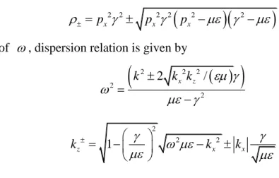
Fig 11 Schematic plot of plane wave with negative refraction. The incident wave is left circular wave(blue) and only left transmitted circular emerge bur twist downward.
Fig 12 Real field pattern while negative refraction occur.
Although the wave vector (4.3) shows direct implication for negative refraction, however, it is only valid when material is isotropic. Another perspective toward negative refraction is to determine the sign of k based on direction of energy flow z as in anisotropic case. In reflection and refraction problem energy must flow toward positive z direction such that refraction occurs, which is indicated by z component of Poynting vector. The sign and magnitude of k is already determined through phase x matching condition so it is convenient to re-derive eigenmode and Poynting vector in terms of k . Following the same procedure as above, we could get: x
Dispersion relation:
22
z x
p p (4.28)
Eigenmodes:
For pz px2
2 (LHCP)
/
1
z x
x
p p i
E p
(4.29)
Impedance:
Z i
(4.30)
Magnetic field: