明新科技大學 校內專題研究計畫成果報告
計畫類別: 任務型計畫 整合型計畫 █個人計畫
計畫編號:MUST-97-資管-04_
執行期間: 97 年 3 月 1 日至 97
年 9 月 30 日
計畫主持人: 邱川峰
計畫參與人員:蘇建銘
張寧馨
處理方式:公開於校網頁
執行單位:資訊管理系
中 華 民 國
97 年
9 月 30
日
點對點同儕網路與網路拓墣架構一致性之研究
英文摘要
In recent years, Peer-to-Peer overlay network is a popular medium especially for
documents or files sharing and have many features including no central server
and peers are equal. But there exists a mis-match problem between peer-to-peer
overlay network and physical network topology. Because when the files are
transmitted between peers that are closed in peer-to-peer overlay network, the
physical network location of the peers are not closed. This results inefficient
transmission or routing between peers in the peer-to-peer overlay network. On
the other hand, the situation will have serious delay in real-time service, for
example streaming service. Therefore, our work proposes a mechanism based on
physical network hop information and situation that is different from traditional
approach that using network delay information as the information to construct
the peer-to-peer overlay network and adjust the arrangement of peer-to-peer
overlay network dynamically. On the other hand, we also design a middleware
implementation of intelligent home network environment to make our proposed
mechanism in practical. By using peer-to-peer overlay network, we also solve
the heterogeneous network topology in intelligent home network environment
design.
Table of Content
1. INTRODUCTION ... 1
2. RELATED WORK... 1
3. PROPOSED METHOD ... 5
3.1. PROBLEM ILLUSTRATION ... 5
3.2. OVERLAY TOPOLOGY IMPROVEMENT SCHEME ... 6
3.2.1. NETWORK HOP TRACER MECHANISM... 6
3.2.2. HOPK-BASED OPTIMIZATION SCHEME... 7
4. PRACTICAL APPLICATION DEMONSTRATION ... 9
4.1 APPLICATION MOTIVATION ... 9
4.2. UPNP OPERATION OVER P2P ... 10
4.2.1. GENERIC MESSAGE MIDDLEWARE... 10
4.2.2. SERVICE DISCOVERY AND ADVERTISEMENT ...11
4.2.3. SERVICE DESCRIPTION ACQUIRING AND CONTROL... 12
4.3. SMART HOME NETWORK ARCHITECTURE ... 13
4.3.1. PROTOCOL STACK ... 13
4.3.2. SOFTWARE ARCHITECTURE ... 14
4.4. SERVICE COLLABORATION FRAMEWORK... 15
4.4.1. SERVICE PLANNING... 15
4.4.2. SERVICE COMPOSITION MECHANISM ... 16
4.4.3. SERVICE EXECUTION ... 18
4.4.4. IMPLEMENTATION... 19
5. CONCLUSION... 22
REFERENCE... 22
Figures
Figure 1 : Overlay Network and Underlying Network Topology ... 1
Figure 2 : An Example of Query Message in Gnutella[6] ... 2
Figure 3 : An Example of Query Message in Freenet[7] ... 2
Figure 4 : An Example of Fasttrack[8]... 3
Figure 5 : An Example of CAN[1]... 3
Figure 6 : An Example of Chord[2] ... 4
Figure 7 : An Example of Revisit Path ... 6
Figure 8 : traceroute tool Example from Minghsin University to Yahoo... 6
Figure 9 : Network Hop Tracer Example... 7
Figure 10 : tracerHop-K Algorithm ... 7
Figure 11 : Argument Network Topology Example ... 8
Figure 12 : HopK-Based Optimization Scheme ... 9
Figure 13 : Generic Message Middleware with P2P overlay network...11
Figure 14 : Overall processing flowchart of UPnP message...11
Figure 15 : MSEARCH message over P2P network... 12
Figure 16 : NOTIFY message over P2P network ... 12
Figure 17 : Service acquiring message over P2P network ... 13
Figure 18 : Control message over P2P network... 13
Figure 19 : Protocol stack illustration ... 14
Figure 20 : The middleware software architecture ... 15
Figure 21 : Service Planning Example... 16
Figure 22 : Service Diagram I... 17
Figure 23 : Service Diagram II ... 17
Figure 24 : Service Diagram III ... 17
Figure 25 : Service Diagram IV... 17
Figure 26 : Service Diagram V ... 18
Figure 27 : Service Planning Example... 18
Figure 28 : Description Language Set of Service Collaboration Framework... 20
Figure 29 : An Example of Service Planning Description Document ... 20
Figure 30 : An Example of Service Execution Description Document ... 21
1. INTRODUCTION
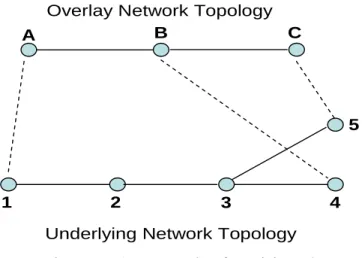
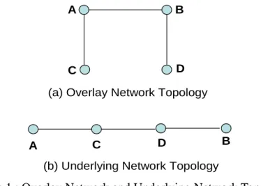
In recent year peer-to-peer overlay network have been became a popular application model to provide several applications including file-sharing, load balance etc.. Peer-to-peer overlay network is a distributed and virtual architecture without considering underlying network topology. Gnutella, Freenet, Naspter, CAN, Chord, Pastry, Tapestry are the famous peer-to-peer overlay network architecture to realize these usage. Because the hosts in the peer-to-peer overlay network are connected in a virtual way, the data transferring do not consider the efficient usage of underlying network topology. When a host transmits a data to another host, the transmission path will be according to overlay network topology. Therefore, the nearby host in peer-to-peer overlay network might have long distance in the underlying network so that the efficiency of transferring might be in worse situation. This problem is called mismatch problem in peer-to-peer overlay network. Now we can consider the overlay network and underlying network topology relationship in Figure 1. When host A transfer a data piece to host B according to the overlay network topology in Figure 1. The actual data transferring path is AÆCÆDÆB according to the underlying network in Figure 1. The actual transmission path is not reflected with the better topology in overlay network. We can consider another scenario according to the Figure 1. When host A send a data piece to host D, the data will be transferred from host A to host D via host B. But the actual transmission path will be AÆCÆDÆBÆD, the path between host B and host D are visited twice and cause the redundant messages to degrade the network performance and overall throughput.
Figure 1 : Overlay Network and Underlying Network Topology
A B
C D
A C D B
(a) Overlay Network Topology
(b) Underlying Network Topology
Therefore, in this research we focus on the investigation of the mismatch problem and consider the solution to resolve. On the other hand, we also apply this result to establish an intelligent home network environment over peer-to-peer overlay network.
2. RELATED WORK
In this section, we will investigation the literatures related with the peer-to-peer overlay network and mismatch problem in overlay network.
Fasttrack/KaZaA[9], BitTorrent[10] etc.. The hosts in these overlay network are connected in a random and distributed way. In order to query the data pieces in overlay network, these overlay network use flooding, random walks or expanding-rich TTL approaches to query data pieces. Figure 2 and Figure 3 shows the search example with respect to Gnutella[6] and Freenet[7]. The query message is sent to other peers to search the needed data pieces and the query message is also forwarded by these intermediate hosts to enhance the query scope. But the problem that message will be sent and reply in a long period will be produced. Therefore, another architecture Fasttrack/KaZaA[10] is proposed to enhance the query performance. In this architecture, a super node is proposed to index the data pieces and the nodes hold the data pieces belong to the super node. The hosts in overlay network are organized as the hierarchy architecture. Figure 4 shows the example of Fasttrack[8].
Figure 2 : An Example of Query Message in Gnutella[6]
Figure 4 : An Example of Fasttrack[8]
Another kind of peer-to-peer overlay network is structured peer-to-peer overlay network. The famous are CAN[1], Chord[2], Pastry[3] and Tapestry[4]. These architectures are based on Distributed Hash Table(DHT) mechanism to allocate the hosts in the overlay network. DHT assign key to the data and compute a value for the key. The (key, value) pair is used for retrieving and locating the data item on a peer. CAN[1] is the first architecture of peer-to-peer overlay network. The hosts are located in a geographic way. The overall hosts’ spaces are divided into d-dimension Cartesian coordinated spaces. Each host in overlay network belongs to on a distinct zone in the overlay network. Figure 5 shows the example of the CAN[1].
Figure 5 : An Example of CAN[1]
Figure 6 : An Example of Chord[2]
The above peer-to-peer overlay networks all have mismatch problem because they do not consider the underlying network topology in constructing the overlay network. Liu et al. propose several solutions to resolve the mismatch problem for unstructured pee-to-peer overlay network. In 2004, Liu et al.[12] propose a location-ware topology matching(LTM) technique to solve mismatch problem in unstructured peer-to-peer overlay network. In LTM host does not require global topology of peer-to-peer overlay network to optimize the overlay network structure. LTM issue a detector to detect the delay information in a constrained range(hops) and hosts collect these information to estimate the optimized overlay network structure. At the same time, Liu et al.[13] also propose another mechanism Adaptive Connection Establishment(ACE) algorithm to resolve the mismatch problem. Hosts collect the delay information by send the probing message and then calculate the minimum spanning tree as the optimized overlay structure according to the collecting delay information. Based on the optimized overlay structure, the host will probe other hosts to find the other closed host and try to establish overlay connection with the better host. Another mechanism scalable bipartite overlay scheme(SBO) is proposed by Liu et al.[31] to resolve the mismatch problem and that is similar with the ACE algorithm. But SBO divide the hosts into two types, one is responsible for collecting delay information and the other is responsible for calculate the optimized overlay structure. Therefore, overall performance of algorithm of finding optimized overlay network is improved.
Xin Yan Zhang et al.[22] propsoe mOverlay to resolve mismatch problem also. They take the locality of the hosts, i.e. distance, into account to construct the overlay network by using dynamic landmark. They introduce the group concept that hosts in group have same distance with group’s neighbors. The group’s neighbors are the dynamic landmark node to find the minimum distance.
Tongqing Qiu et al.[23] propose a generic approach to construct the topology-aware overlay network and they also use landmark as the basic scheme. By using the information from the landmark, the two hosts will be swapped to have better performance in overlay network. The decision for swapping is based on the calculation of delay information before swapping and after swapping. If the performance before swapping is better than after swapping, the two hosts will not swap to exchange hosts’ information. Otherwise, they swapped to have better overlay network topology.
closed host can not be found in the lower hierarchy, they will search for high layer hierarchy to find the closed hosts. Based on the two hierarchy architecture, the locality of the hosts in overlay network can be realized to solve the mismatch problem.
Guoqiang Zhang et al.[25] propose a simple approach to solve mismatch problem by collecting global information from BGP table in Internet. The global information reveals the global information with respect to the hosts in the overlay network. Therefore, the topology-aware topology can be constructed in a simple way.
Zhichen Xu et al.[15] combine landmark clustering and RTT measurement have accuracy information to construct topology-aware overlay network topology. Kai Shen et al.[27] use landmark hierarchy information as the basis to construct self-organized DHT protocol to have better structured peer-to-peer overlay network topology. Sylvia Rantnasamy et al.[28] use landmark information to calculate the network latency and they present binning scheme to divide the hosts into different clusters based the landmark information. Therefore, the hosts in the same cluster will have short distance and the better overlay structure is established. Shansi Ren et al.[16] use the TTL-k flooding and RTT measurement to have the latency information within k hops. Based on the information, they will adaptive estimate the overlay network topology to solve mismatch problem. Demetrios Zeinalipour-Yazti et al.[30] propsoe domain name server ordering scheme to solve mismatch problem by helping with domain name server. The hosts have same domain name server ordering will be closed with respect to the underlying network topology.
The basic solution of the above literatures is to gather the topology status of the hosts in overlay network and then produces the optimized topology. The topology status is defined as the delay information between hosts. But in our opinion, the delay information just reveals the performance of the association path between hosts in overlay network and can not represent the actual topology of the overlay network. Therefore, our proposed method does not consider the delay information only and we also take the underlying network hop information into account.
3. PROPOSED METHOD
3.1. PROBLEM ILLUSTRATION
Figure 7 : An Example of Revisit Path
A B C
Overlay Network Topology
Underlying Network Topology
1 2 3 4
5
3.2. OVERLAY TOPOLOGY IMPROVEMENT SCHEME
3.2.1. NETWORK HOP TRACER MECHANISM
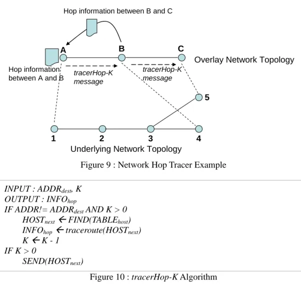
Based on our observation, we introduce network hop-based counting and detect the revisit edges along the query path to make the overlay network topology-aware. In practical, we can use network diagnose tool, traceroute or tracert, to explore the network path. These tools can trace the network address from source host to destination host so that the network hop can be recognized. Figure 8 is an example of that using traceroute tool from Minghsin University to Yahoo homepage.
Figure 8 : traceroute tool Example from Minghsin University to Yahoo
Figure 9 : Network Hop Tracer Example
A B C
Overlay Network Topology
Underlying Network Topology
1 2 3 4
5 Hop information between B and C
tracerHop-K message Hop information between A and B tracerHop-K message
Figure 10 : tracerHop-K Algorithm INPUT : ADDRdest, K
OUTPUT : INFOhop
IF ADDR!= ADDRdest AND K > 0
HOSTnextÅ FIND(TABLEhost)
INFOhopÅ traceroute(HOSTnext)
K Å K - 1 IF K > 0
SEND(HOSTnext)
3.2.2. HOPK-BASED OPTIMIZATION SCHEME
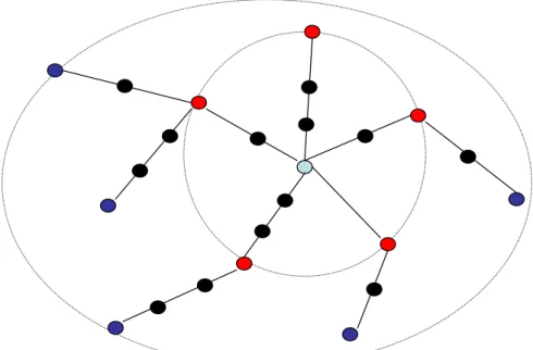
Figure 11 : Argument Network Topology Example
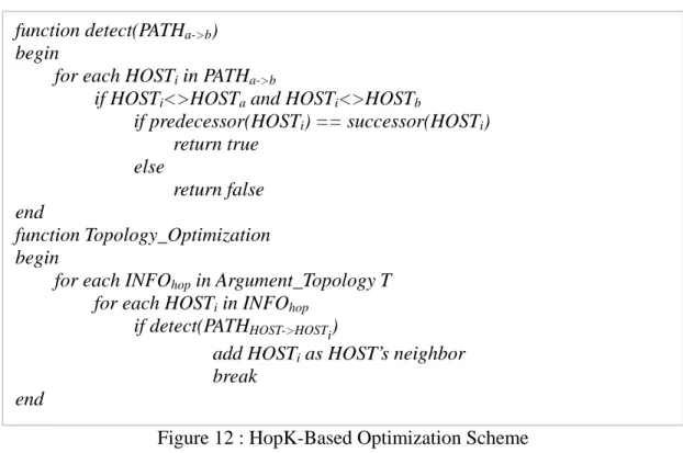
When the host constructs the argument network topology, the host will detect the repeat edges or cycle edges in the argument network topology and add the final host in the path to the host’s neighbor. Figure 12 is the algorithm of the HopK-Based optimization scheme. The algorithm will be executed in each host of peer-to-peer overlay network periodically.
In general, the overall network is a summation of transmission delay, queuing delay, propagation delay and processing delay. Equation (1) is the formula that describes the overall network delay of peer-to-peer overlay network.
∑ ∑
∑ ∑
= + + + = n m i t q p pro n m i host network D D D D D D 1 1 (1)Dnetwork is the overall network delay of peer-to-peer overlay network. Dhost is the network
delay with respect to host of peer-to-peer overlay network. Dt is the transmission delay, Dq is
the queuing delay, Dp is the propagation delay and Dpro is the processing delay. Because our
Figure 12 : HopK-Based Optimization Scheme function detect(PATHa->b)
begin
for each HOSTi in PATHa->b
if HOSTi<>HOSTa and HOSTi<>HOSTb
if predecessor(HOSTi) == successor(HOSTi) return true else return false end function Topology_Optimization begin
for each INFOhop in Argument_Topology T
for each HOSTi in INFOhop
if detect(PATHHOST->HOSTi)
add HOSTi as HOST’s neighbor
break end
4. PRACTICAL APPLICATION DEMONSTRATION
In previous sections, we have illustrated the scheme to resolve topology mismatch in peer-to-peer overlay network to improve the overall performance. In order to make the mechanism practical, we design an intelligent home environment in the following sub sections based on our propose scheme and UPnP protocol[17].
4.1 APPLICATION MOTIVATION
Because of the population of network usage, traditional home network have move on digital era. Home devices in the traditional home network are operating individually and can not communicate with other devices. Through network connection home devices will be connected with each other and work cooperatively. In order to provide seamless connection within home network, UPnP[17] is the most popular technology to realize the home network operations. The most important operation of UPnP technology is device/service discovery. Through device/service discovery, home devices can be aware which devices or services are available to use. However the device/service discovery mechanism is using broadcast messages. There are two major problems arising from the broadcast message. First, each device will send broadcast message to others, so that the network performance will be decreased. Second, because of broadcast message is sent over reserved broadcast IP address, therefore, broadcast message will not be sent across to other network segment. Otherwise, the router or gateway needs to be modified to support broadcasting across to other segments. So the heterogeneous environment will decrease the usage of home network.
underlying network segment. Therefore, we take the advantage of the peer-to-peer overlay network architecture, we propose an implementation for UPnP operations over peer-to-peer overlay network. Through the implementation, the number of broadcast message will be reduced and message can be delivered without affecting by the mixed underlying network architecture.
On the other hand, when home user use their own mobile device, for example, PDA or mobile phone, to control home appliances within home network and move outside home network, home user will not control home device directly. Although we can deploy a home gateway to solve such kind of scenario, this will increase more complicate configuration and cost. Therefore, our work proposed in this research can meet the demand of flexible home usage also.
Besides the seamless integration of different network, to manipulate service easily is also a basic demand for home users and intelligent usage of home service is also an important feature to realize a smart home environment. In this paper, we also propose a service collaboration framework based on service planning to provide an easy use home environment for home users.
4.2. UPNP OPERATION OVER P2P
In this section, we reveal the design of the UPnP message transmission over peer-to-peer overlay network. The following sub-sections describe P2P-based UPnP device/service discovery and advertisement, UPnP service description acquiring, UPnP service control and event.
4.2.1. GENERIC MESSAGE MIDDLEWARE
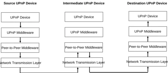
When UPnP device join the home network, the UPnP device perform the join operation of peer-to-peer overlay network and establish the neighbor list of the UPnP devices. And then UPnP message could be sent over peer-to-peer overlay network. Originally, the UPnP message delivery will be sent via network interface directly. The solution of our propose method is to deliver UPnP message via peer-to-peer overlay network which do not need to consider the underlying network architecture. Figure 13 show the message flow over peer-to-peer network. When UPnP device send an UPnP message, the message will be transferred to peer-to-peer middleware which look up the address of destination device. If the middleware could not decide the destination address, the message will be sent to proper intermediate device to look up destination device via peer-to-peer routing mechanism and network transmission layer in advance. Therefore, the next device or destination device will be decided by the peer-to-peer middleware.
Figure 13 : Generic Message Middleware with P2P overlay network
UPnP Device
UPnP Middleware
Peer-to-Peer Middleware
Network Transmission Layer
UPnP Device
UPnP Middleware
Peer-to-Peer Middleware
Network Transmission Layer
UPnP Device
UPnP Middleware
Peer-to-Peer Middleware
Network Transmission Layer
Source UPnP Device Intermediate UPnP Device Destination UPnP Device
Figure 14 : Overall processing flowchart of UPnP message
Generating hash value of the message Lookup receiving pool Exist? Ignore the message Check message type
Generating relay list =
neighborhood list – message sending peer
Reply the message to relay list
Process the message with corresponding
actions
Is destination peer?
Forward the message to next peer with p2p
routing mechanism Receiving message NO YES Service discovery/advertisement
Service description acquiring or service control
YES NO
4.2.2. SERVICE DISCOVERY AND ADVERTISEMENT
Device/service discovery and advertisement are the most important operation in UPnP. When UPnP device join or leave the home network, discovery and advertisement message is used to guarantee the availability of the devices. The discovery and advertisement mechanism comprise two kind of message including MSEARCH and NOTIFY.
overlay network. When a node receives the MSEARCH message, the node responses a reply message to the original node with its device identifier. Figure 15 shows the MSEARCH message over peer-to-peer network. Bold line is the MSEARCH message and dash line is the response message with respect to the MSEARCH message. From the figure, we can observe that intermediate node might receive several duplicate messages. As we described in previous section, first comes message will be processed and later duplicate message will be dropped. In addition, in order to avoid too many response messages on the same path, intermediate node will collect all response messages and package into one response message to the original sending node.
Figure 15 : MSEARCH message over P2P network
Source node MSEARCH MSEARCH MSEARCH MSEARCH MSEARCH MSEARCH MSEARCH MSEARCH Source node MSEARCH MSEARCH MSEARCH MSEARCH MSEARCH MSEARCH MSEARCH MSEARCH
When UPnP device notify the awareness of the device actively, the NOTIFY message will be sent. When NOTIFY message is sent, the peer-to-peer middleware perform the join action to participate the device into peer-to-peer overlay network and intermediate node will relay NOTIFY message to its neighbors. Figure 16 shows the NOTIFY message over peer-to-peer network.
Figure 16 : NOTIFY message over P2P network
Source node NOTIFY NOTIFY NOTIFY NOTIFY NOTIFY NOTIFY NOTIFY NOTIFY Source node NOTIFY NOTIFY NOTIFY NOTIFY NOTIFY NOTIFY NOTIFY NOTIFY
4.2.3. SERVICE DESCRIPTION ACQUIRING AND CONTROL
node will reply the service description to the acquiring peer. The acquiring node will cache the service description in the available service pool for future usage. On the other hand, Service description acquiring is an end-to-end action, but devices are located in different network segment. Therefore, service description acquiring is still transmitted alone with peer-to-peer overlay topology. Figure 17 shows the service acquiring message over peer-to-peer network. Service control action is similar with service description acquiring operation which is an end-to-end action also. Therefore, when a node receives the service control command, the node will work according to the received service control command. Figure 18 shows the service control message over peer-to-peer network.
Figure 17 : Service acquiring message over P2P network Service acquiring Service acquiring Service acquiring Service acquiring
Figure 18 : Control message over P2P network
Control msg.
Control msg.
4.3. SMART HOME NETWORK ARCHITECTURE
In this section, we propose the design of the system architecture. First we will reveal the design of the protocol stack to realize the UPnP message over peer-to-peer network. And then the system software architecture which comprises several computing blocks or procedures will be showed.
4.3.1. PROTOCOL STACK
comprising four portions including user/vendor customization part, UPnP middleware, peer-to-peer network middleware and underlying TCP/IP stack.
User/vendor customization : Application developer can design their application with respect their scenario , idea or, usage. And they do not concern the detail of the underlying complex middleware or stack.
UPnP middleware : This is the traditional part of UPnP implementation including all functionalities of UPnP operations and messages.
Peer-to-peer network middleware : This portion is the basic transmission platform. This middleware will perform node joining, node leaving and topology maintenance. In addition, the peer-to-peer middleware will transmit the UPnP messages to destination node or route the message intermediate node also.
TCP/IP protocol stack : This is the actual network transmission layer. The destination node will be resolved by the peer-to-peer middleware and pass the destination node to the TCP/IP layer to perform actual packet transportation.
Figure 19 : Protocol stack illustration
HTTPMU (Discovery) HTTPMU (Discovery) SSDP SSDP GENAGENA HTTPU (Discovery) HTTPU (Discovery) SSDP SSDP SOAP (Control) SOAP (Control) HTTP (Description) HTTP (Description) HTTP HTTP GENA (Events) GENA (Events) UDP UDP TCPTCP IP IP Peer-to-Peer Middleware Peer-to-Peer Middleware
UPnP-enable Device Implementation
UPnP-enable Device Implementation User/ Vendor
customization UPnP middleware implementation Peer-to-peer network middleware Native TCP/IP protocol stack 4.3.2. SOFTWARE ARCHITECTURE
Figure 20 : The middleware software architecture
Network Interface
Receiving pool Service poolMessage
parser/builder
UPnP command
dispatcher
P2P lookup
middleware
Neighborhood informationUser Interface
4.4. SERVICE COLLABORATION FRAMEWORK
In previous section, we have proposed the design of smart home environment based on peer-to-peer overlay network to seamless connecting home appliances in a feasible way. But in order to share and manipulate home service in a flexible approach, we propose a service collaboration framework in this section. Our proposed mechanism is based on service planning to have a collaboration diagram for home service so that the collaboration framework will reduce user effort. The general principle to achieve collaboration between different services on different home appliances is outlined as following.
Service preference : In order to describe different service capability or constrain, to have a easy understanding preference for service is very important. Fortunately, UPnP protocol described in previous section have defined service description based on XML language. The service preference can be described in common and easily.
Service workflow determination : Service is a basic unit for specified task in home environment. Home user will not understand each atomic service very well. And home user manipulates home service that comprises several services involving usually. Therefore to define a workflow that integrates each service is the tool for home users.
Service composition : After defining service workflow, different services can be composed from different home appliances as an atomic-like service so that user effort will be reduced and manipulate service in a more flexible way. The stage is to collect all of the available services and merge into service collaboration diagram.
Service execution : When service composition based on the service workflow, the composed service will be executed. And according to different service state in the service workflow, some of atomic service can be executed in parallel. Therefore, the service execution performance can be improved compared with traditional service manipulation which uses each service in step by step way. The service execution chain is called service execution flow.
4.4.1. SERVICE PLANNING
following scenario. A home user wants to watch a TV show on its PDA and wants to record the show in a storage place in home. Figure 21 shows the workflow of the above scenario and each circle represents a service task. The workflow will be called service planning in this paper. Service planning is high-level process to describe the service component which might be an atomic service or comprising sub-service components.
Figure 21 : Service Planning Example
TV show input Play on PDA Store TV show
4.4.2. SERVICE COMPOSITION MECHANISM
When the service planning is defined, the planning is complied as a service composition diagram. The compile process will recognize the planning into several detail service components and schedule different execution flow to produce different service diagrams that might have synchronous or asynchronous execution path. The service composition mechanism is a recursive process. Each service component from the service planning will be divided into more detail service component that might be atomic service or another service planning. Figure 27 illustrates the result of service diagram extraction process in a hierarchy architecture. The synchronous or asynchronous execution path is produced according to the following definition.
Definition 1 : Sequencing Flow - When the service A is followed service B, service B has a directed flow to service A. That isA→B.
Definition 2 : Concurrent Flow - When service A and service B are independent, service diagram will split two concurrent flows to perform service A and B. That is A∩ B=φ.
Figure 22~Figure 26 shows several service diagrams of the example that is described in previous sub-section. Service diagram I in Figure 22 means a video stream, called TV show in previous section, is the input for playing on the PDA and storing in home storage. Before playing on PDA, the video stream needs to be transferred to another format to play on PDA. On the other hand, video stream can be stored in home storage without transcoding. Service diagram II in Figure 23 means a video stream is the input for playing on the PDA and storing in home storage. Before storing in the home storage, the video stream needs to be transferred to another format. On the other hand, video stream can be played on PDA directly. Service diagram III in Figure 24 means video stream needs to be transferred to another format first and the format is suitable for both PDA and home storage. Service diagram IV in Figure 25 means the video stream needs to be transferred to another two formats to play on PDA and store in home storage. Because of the PDA and home storage require different video format. Service diagram V in Figure 26 means the video stream does not need to be transferred to another format and can be played on PDA and stored in home storage directly.
Figure 22 : Service Diagram I
Video Show
Playing on PDA
Video Transcoding Video Stroing
Figure 23 : Service Diagram II
Video Show
Playing on PDA Video Transcoding
Video Stroing
Figure 24 : Service Diagram III
Video Show
Playing on PDA Video Transcoding A
Video Stroing Video Transcoding B
Figure 25 : Service Diagram IV
Video Show
Playing on PDA Video Transcoding A
Figure 26 : Service Diagram V
Video Show
Playing on PDA Video Stroing
Figure 27 : Service Planning Example
atomic service
atomic service atomic service
atomic service
atomic service
atomic service atomic service
service component service component service component
original service diagram
divided service diagram
4.4.3. SERVICE EXECUTION
(
)
∑
∑
+ − = j j i i L P Cost α 1 α (2)α is an estimated factor to represent the importance of the home appliance processing time and 0≤α ≤1. 1−α shows the importance factor of the network transmission. Pi is the home appliance processing time of device i and Lj is the network transmission time for edge j between two consequence execution devices. The network transmission time comprise the network delay, propagation delay and queuing delay.
4.4.4. IMPLEMENTATION
Service Preference Service Planning Service composition Service Execution
Service Planning Description Language
Service Diagram Description Language
Service Execution Description Language
Service Planning Description Document
Service Diagram Description Document
Service Execution Description Document Figure 28 : Description Language Set of Service Collaboration Framework
<Service_Planning name=“…..”> <Service_Component> <Component_ID>…</Conponent_ID> <Component_Name>…</Component_Name> <Parent_Component>… </Parent_Component> </Service_Component>
…Other Service Component…… </Service_Planning>
<Service_Diagram name=“…..”> <Service_Planning_Name>…</Serivce_Planning_Name> <Service_List> <Sequence_Number>…</Sequence_Number> <Atomic_Service Name=“…”> <Ancestor_Service>…</Ancestor_Service> <Service_Action Name=“…”> <Service_Parameter> <Paramter_Name>…</Parameter__Name> <Paramter_Value>…</Parameter__Value> <Service_Parameter>
….other service parameter…..
</Service_Action>
…other service action…
</Atomic_Service>
…other atomic service……
</Service_List> …Other Service List…… </Service_Diagram>
Figure 30 : An Example of Service Execution Description Document
Figure 31 : An Example of Service Diagram Description Document
<Service_Execution Name=“…..”>
<Execution_Flow Name=“…” Sequence=“…”> <Atomic_Service Name=“…”>
<Ancestor_Service>…</Ancestor_Service> <Device_URL>…<Device_URL>
<Service_Action Name=“…” URL=“…”> <Service_Parameter>
<Paramter_Name>…</Parameter__Name> <Paramter_Value>…</Parameter__Value> <Service_Parameter>
….other service parameter….. </Service_Action>
…other service action… </Atomic_Service>
…other atomic service…. </Execution Flow>
5. CONCLUSION
In this research, we introduce using network hop information as the estimation factor to resolve mismatch problem between peer-to-peer overlay network and underlying network. From the transmission path analysis, we can discover the propose approach that can improve the peer-to-peer overlay network topology according to the network hop information between each virtual connection hosts. In order to make the method practically, we also propose a middleware implementation for home network to extend the UPnP operations which is originally restricted by broadcast message based on our proposed method. Based on the designed middleware using peer-to-peer overlay network, the home network message can be transmitted cross different network segment and do not need to modify the underlying network equipments. And based on the message transmission over peer-to-peer network, the number of broadcast message can be reduced and make the network usage efficient. On the other hand, in order to provide a smart home service environment, we also propose a service collaboration framework which is based on XML technology. Because our proposed middleware is based on peer-to-peer overlay network, there exists security issue including DoS attack between these peers. Therefore, a better security mechanism will be the most important task in the future. On the other hand, service planning in the service collaboration framework is generated by home users. In order to provide an automatic environment, service semantic composition is also a future research direction.
REFERENCE
[1]. S. Ratnasamy, P. Francis, M. Handley, R. Karp, and S. Shenker, "A scalable content addressable network," in Proceedings of the ACM SIGCOMM, 2001, pp. 161-172 [2]. Stoica, R. Morris, D. Karger, M. F. Kaashoek, and H. Balakrishnan, "Chord: A scalable
peer-to-peer lookup protocol for internet applications," IEEE/ACM Transitions on Networking, vol. 11, no. 1, pp. 17-32, 2003
[3]. Rowstron and P. Druschel, "Pastry: Scalable, distributed object location and routing for large-scale peer-to-peer systems," on Proceedings of the Middleware, 2001
[4]. Y. Zhoa, L. Huang, J. Stribling, S. C. Rhea, A. D. Joseph, and J. D. Kubiatowica, "Tapestry: A resilient global-scale overlay for service deployment," IEEE Journal on Selected Areas in Communications, vol. 22, no. 1, pp41-53, January 2004
[5]. Napster.[Online]. available: http://www.napster.com/
[6]. (2001)Gnutella development forum, the gnutella v0.6, [Online]. Avaliable: http://groups.yahoo.com/group/the_pdf/files/
[7]. Clarke, O. Sandberg, B. Wiley, and T. W. Hong.(1999) Freenet: A distributed anonymous information storage and retrieval system. Freenet White Paper. [Onlin]. Available: http://freenetproject.org/freenet.pdf
[8]. (2001)Fasttrack peer-to-peer technology company. [Online]. Available : http://www.fasttrack.nu/
[9]. (2001)Kazaa mdeia desktop. [Online]. Available: http://www.kazaa.com/ [10]. (2003)Bittorrent. [Online]. Available: http://bitconjurer.org/BitTorrent/
[11]. E Lua,J Crowcroft,M Pias,et al. “A survey and comparison of peer-to-peer overlay network schemes”. IEEE Communications Survey and Tutorial,2005,7(2), pp. 72-93 [12]. Yunhao Liu, Li Xiao, Xiaomei Liu, Lionel M. Ni, and Xiaodong Zhang, "Location
Awareness in Unstructureed Peer-to-Peer Systems," IEEE Transaction on Parallel and Distributed Systems, vol. 16, no. 2, pp. 163-174, February 2005
by Adaptive Connection Establishment,", vol. 54, no. 9, pp. 1091-1103, September 2005 [14]. M. Waldvogel and R. Rinaldi, "Efficient topology-aware overlay network," in
Proceedings of HotNets-I Princeton, NJ, USA, October 2002
[15]. Z. Xu, C. Tang, and Z. Zhang, " Building topology-aware overlays using global soft-state," in Proceedings of ICDCS 2003, pp. 500-508, Providence, RI, USA, May, 2003
[16]. Shansi Ren, Lei Guo, Song Jiang, and Xiaodong Zhang, “SAT-Match: A Self-Adaptive Topology Matching Method to Achieve Low Lookup Lantency in Structured P2P Overlay Networks,” in Proceedings of the 18th International Parallel and Distributed Processing Symposium, New York: IEEE Press, 2004. pp. 83-91
[17]. UPnP Forum, avaliable: http://www.upnp.org.
[18]. Dong-Sung Kim, Jae-Min Lee, Wook Hyun Kwon, In Kwan Yuh, "DESIGN AND IMPLEMENTATION OF HOME NETWORK SYSTEMS USING UPnP MIDDLEWARE FOR NETWORKED APPLIANCES", IEEE Transactions on Consumer Electronics, Vol. 48, No. 4, NOVEMBER 2002, pp. 963-972.
[19]. Young-Guk Ha, Joo-Chan Sohn and Young-Jo Cho, "ubiHome: An Infrastructure for Ubiquitous Home Network Services", in Proceedings of IEEE International Symposium on Consumer Electronics(ISCE 2007), Irving, TX, USA, 20-23 June 2007, pp.1-6. [20]. Xie Li and Wenjun Zhang, "The Design and Implementation of Home Network System
Using OSGi Compliant Middleware", IEEE Transactions on Consumer Electronics, Vol. 50, No. 2, MAY 2004, pp.528-534.
[21]. Kyeong-Deok Moon, Young-Hee Lee, and Young-Sung Son, Chae-Kyu Kim, "Universal Home Network Middleware Guaranteeing Seamless Interoperability among the Heterogeneous Home Network Middleware", IEEE Transactions on Consumer Electronics, Vol. 49, No. 3, AUGUST 2003, pp.546-553.
[22]. Xin Yan Zhang, Qian Zhang, Member, Gang Song, and Wenwu Zhu, "A Construction of Locality-Aware Overlay Network:mOverlay and Its Performance", IEEE JOURNAL ON SELECTED AREAS IN COMMUNICATIONS, VOL. 22, NO. 1, JANUARY 2004, pp18-28.
[23]. QIU Tong-Qing, CHEN Gui-Hai, "A Generic Approach to Making P2P Overlay Network Topology-Aware", Journal of Software, Vol.18, No.2, February 2007, pp.381-390.
[24]. Guangtao Xue, Yi Jiang, Jinyuan You, Minglu Li, "A Topology-Aware Hierarchical Structured Overlay Network based on Locality Sensitive Hashing Scheme", in Proceedings of the second on the Use of P2P, GRID and Agents for the Development of Content Networks(UPGRADE-CN'07), June 26, 2007, Monterey, California, USA. pp. 3-8.
[25]. Guoqiang Zhang, "Agent Selection And P2P Overlay Construction Using Global Locality Knowledge", in Proceedings of the 2007 IEEE International Conference on Networking, Sensing and Control, London, UK, 15-17 April 2007. pp. 519-524.
[26]. Xu, Z., Tang, C., and Zhang, Z. 2003. Building Topology-Aware Overlays Using Global Soft-State. In Proceedings of the 23rd international Conference on Distributed Computing Systems (May 19 - 22, 2003). ICDCS. IEEE Computer Society, Washington, DC, pp.500-508.
[27]. Kai Shen and Yuan Sun, "Distributed Hashtable on Pre-structured Overlay Networks", in Proceedings of 9th International Workshop, WCW 2004, Beijing, China, October 18-20, 2004. pp. 63-81.
Conference of the IEEE Computer and Communications Societies(INFOCOM2002). pp. 1190-1199.
[29]. Shansi Ren, Lei Guo, Song Jiang, Xiaodong Zhang, "SAT-Match: a self-adaptive topology matching method to achieve low lookup latency in structured P2P overlay networks", in Proceedings of 18th International Parallel and Distributed Processing Symposium(IPDPS2004), 2004. pp. 26-30.
[30]. Demetrios Zeinalipour-Yazti, Vana Kalogeraki, "Structuring topologically aware overlay networks using domain names", Computer Networks, Volume 50 , Issue 16 , 2006, pp. 3064–3082.
[31]. Yunhao Liu, Li Xiao, and Lionel M Ni, "Building a Scalable Bipartite P2P Overlay Network", IEEE Transactions on Parallel and Distributed Systems, Vol. 18, No. 9, September 2007, Pages 1296-1306.
APPENDIX
國際研討會論文發表一篇:
The Design of UPnP-based Home Environment over Peer-to-Peer Overlay
Network
Chuan-Feng Chiu, Steen J. Hsu, Sen-Ren Jan Department of Information Management Minghsin University of Science and Technology
E-mail : [email protected]
Abstract
With the population of network usage, it is possible to connect home appliances with each other. The basic demand is to connect home appliances easily with less user intervening. UPnP is the most popular technology for realizing digital home. UPnP provide service and device discovery by sending broadcast message periodically. Therefore, this causes efficiency problem arising from many broadcast messages. In addition, home network is an emergence environment which might comprise several network architecture including ethernet, wireless network, or power-line etc.. Therefore, traditional broadcast will not work well in the complex network architecture. In order to solve the above problems, we propose a middleware implementation to realize UPnP operations over peer-to-peer overlay network.
1. Introduction
Because of the population of network usage, traditional home network have move on digital era. Home devices in the traditional home network are operating individually and do not have communication with other devices. Through network connection home devices will be connected with each other and work cooperatively. In order to provide seamless connection within home network, UPnP is the most popular technology to realize the home network operations. The most important operation of UPnP technology is device/service discovery. Through device/service discovery, home devices can be aware which devices or services are available to use. However the device/service discovery mechanism is using broadcast messages. There are two major problems arising from the broadcast message. First, each device will send broadcast message to others, so that the network performance will be poor. Second, because of
broadcast message is sent over reserved broadcast IP address, therefore, broadcast message will not be sent across to other network segment. Otherwise, the router or gateway needs to be modified to support broadcasting across to other segments.
Therefore, in order to resolve the above problem, we need to reduce the number of broadcast message and generic transfer architecture to support multi-segment network architecture. Fortunately, with the development of peer-to-peer overlay network architecture multi-segment issue can be resolved easily. In peer-to-peer network, messages can be relayed by intermediate peers and do not consider underlying network segment. Therefore, we take the advantage of the peer-to-peer overlay network architecture, we propose an implementation for UPnP operations over peer-to-peer overlay network. Through the implementation, the number of broadcast message will be reduced and message can be delivered without considering the underlying multi-segment architecture.
On the other hand, when home user use their own mobile device, for example, PDA or mobile phone, to control home appliances within home network and move outside home network, home user will not control home device directly. Because UPnP do not work well between in-home and outside-home. Although we can deploy a home gateway to solve such kind of scenario, this will increase more complicate configuration and cost. Therefore, our work proposed in this paper can meet the demand of flexible home usage also.
2. Related work
UPnP[1] is the most popular implementation to realize home network and it can enable data communication between home devices via a set of UPnP commands. The major operations including service discovery, service advertisement service acquiring and service control and these operations are transmitted over HTTP protocol. UPnP comprise several standards such as Simple Device Discovery Protocol, Simple Object Access Protocol and General Notification Architecture to perform service discovery, service description acquiring and service control and notification. Two kinds of roles are defined in UPnP. One is UPnP Control Point and the other is UPnP Device. UPnP Control Point is the device that can issue manipulation command to ask UPnP device to perform some actions. And UPnP Device is to provide the available services for UPnP Control Point. Figure n is the general representation between UPnP Control Point and UPnP Device.
Peer-to-peer network is a popular virtual network architecture in recent year. It can provide resource sharing in a distributed way. It resides on underlying network architecture and is a distributed architecture without central server involving. The first peer-to-peer network is Napster[4]. It deploy a central server as an index server, each peer can find the location of interest data items from the index server and contact the corresponding peer directly. With the development of peer-to-peer network, two peer-to-peer network architectures are appeared. One is Unstructure peer-to-peer network and the other is Structure peer-to-peer-to-peer-to-peer network. Gnutella[3] is such kind of Unstructure peer-to-peer network. Peers are connected in a distributed way and do not need to know overall topology. It uses flooding as the mechanism to send query to find the related information. In Structure peer-to-peer network, it assign key to the data and compute a value for the
key. The (key, value) pair is used for retrieving and
locating the data item on a peer. CAN[5], Chord[6], Pastry[7] and Tapestry[8] are the famous Structure peer-to-peer network system. Unlike flooding in Unstructure peer network, Structure peer-to-peer network routing can be bounded in O(logN) hops. 3. UPnP operations over P2P
In this section, we reveal the design of the UPnP message transmission over peer-to-peer overlay network. The following sub-sections describe P2P-based UPnP device/service discovery and
advertisement, UPnP service description acquiring, UPnP service control and event.
3.1. Generic message middleware
When UPnP device join the home network, the UPnP device perform the join operation of peer-to-peer overlay network and establish the neighbor list of the UPnP devices. And then UPnP message could be sent over peer-to-peer overlay network. Originally, the UPnP message delivery will be sent via network interface directly. The solution of our propose method is to deliver UPnP message via peer-to-peer overlay network which do not need to consider the underlying network architecture. Figure 1 show the message flow over peer-to-peer network. When UPnP device send an UPnP message, the message will be transferred to peer-to-peer middleware which look up the address of destination device. If the middleware could not decide the destination address, the message will be sent to proper intermediate device to look up destination device via peer-to-peer routing mechanism and network transmission layer in advance. Therefore, the next device or destination device will be decided by the peer-to-peer middleware.
UPnP Device
UPnP Middleware Peer-to-Peer Middleware Network Transmission Layer
UPnP Device UPnP Middleware Peer-to-Peer Middleware Network Transmission Layer
UPnP Device UPnP Middleware Peer-to-Peer Middleware Network Transmission Layer
Source UPnP Device Intermediate UPnP Device Destination UPnP Device
Generating hash value of the message Lookup receiving pool Exist? Ignore the message Check message type Generating relay list =
neighborhood list – message sending peer Reply the message to
relay list
Process the message with corresponding
actions
Is destination peer?
Forward the message to next peer with p2p routing mechanism Receiving message NO YES Service discovery/advertisement
Service description acquiring or service control
YES NO
Figure 2. Overall processing flowchart of UPnP message
3.2. Service discovery and advertisement
Device/service discovery and advertisement are the most important operation in UPnP. When UPnP device join or leave the home network, discovery and advertisement message is used to guarantee the availability of the devices. The discovery and advertisement mechanism comprise two kind of message including MSEARCH and NOTIFY.
Source node MSEARCH MSEARCH MSEARCH MSEARCH MSEARCH MSEARCH MSEARCH MSEARCH
Figure 3. MSEARCH message over P2P network If the device wants to know other devices, MSEARCH message will be sent. When MSEARCH message is sent, the message will be relayed to every node of the peer-to-peer overlay network. When a node receives the MSEARCH message, the node responses a reply message to the original node with its device identifier. Figure 3 shows the MSEARCH message over peer-to-peer network. Bold line is the MSEARCH message and dash line is the response message with respect to the MSEARCH message. From the figure, we can observe that intermediate node might receive several duplicate messages. As we described in section 3.1, first comes message will be processed and later duplicate message will be dropped. In addition, in order to avoid too many response messages on the same path, intermediate node will
collect all response messages and package into one response message to the original sending node.
When UPnP device notify the awareness of the device actively, the NOTIFY message will be sent. When NOTIFY message is sent, the peer-to-peer middleware perform the join action to participate the device into peer-to-peer overlay network and intermediate node will relay NOTIFY message to its neighbors. Figure 4 shows the NOTIFY message over peer-to-peer network. Source node NOTIFY NOTIFY NOTIFY NOTIFY NOTIFY NOTIFY NOTIFY NOTIFY
Figure 4. NOTIFY message over P2P network
3.3. Service description acquiring and control
When peer has device identifier and related information, the peer can issue service acquiring message to get the service description over peer-to-peer overlay network. And then acquired node will reply the service description to the acquiring peer. The acquiring node will cache the service description in the available service pool for future usage. On the other hand, Service description acquiring is an end-to-end action, but devices are located in different network segment. Therefore, service description acquiring is still transmitted alone with peer-to-peer overlay topology. Figure 5 shows the service acquiring message over peer-to-peer network. Service control action is similar with service description acquiring operation which is an end-to-end action also. Therefore, when a node receives the service control command, the node will work according to the received service control command. Figure 6 shows the service control message over peer-to-peer network.
Service acquiring Service acquiring
Control msg. Control msg.
Figure 6. Control message over P2P network 4. System architecture
In this section, we propose the design of the system architecture. First we will reveal the design of the protocol stack to realize the UPnP message over peer-to-peer network. And then the system software architecture which comprises several computing blocks or procedures will be showed.
4.1. Protocol stack
In order to make less modification on existing protocol stack, we insert an add-on peer-to-peer network middleware between UPnP middleware implementation and underlying TCP/IP protocol stack. The overall protocol stack is showed in Figure 7. The overall protocol stack comprising four portions including user/vendor customization part, UPnP middleware, peer-to-peer network middleware and underlying TCP/IP stack.
User/vendor customization : Application developer
can design their application with respect their scenario , idea or, usage. And they do not concern the detail of the underlying complex middleware or stack.
UPnP middleware : This is the traditional part of
UPnP implementation including all functionalities of UPnP operations and messages.
Peer-to-peer network middleware : This portion is
the basic transmission platform. This middleware will perform node joining, node leaving and topology maintenance. In addition, the peer-to-peer middleware will transmit the UPnP messages to destination node or route the message intermediate node also.
TCP/IP protocol stack : This is the actual network
transmission layer. The destination node will be resolved by the peer-to-peer middleware and pass the destination node to the TCP/IP layer to perform actual packet transportation. HTTPMU (Discovery) HTTPMU (Discovery) SSDP SSDP GENAGENA HTTPU (Discovery) HTTPU (Discovery) SSDP SSDP SOAP (Control) SOAP (Control) HTTP (Description) HTTP (Description) HTTP HTTP GENA (Events) GENA (Events) UDP UDP TCPTCP IP IP Peer-to-Peer Middleware Peer-to-Peer Middleware UPnP-enable Device Implementation
UPnP-enable Device Implementation User/ Vendor customization UPnP middleware implementation Peer-to-peer network middleware Native TCP/IP protocol stack
Figure 7. Protocol stack illustration
4.2. Software architecture
The protocol stack in previous section reveals the protocol architecture for realizing the home network scenario. In this section, we describe the software architecture for UPnP operations over peer-to-peer network. All messages are received and sent by the underlying network interface. The received packet will passed to message processor which perform message parsing and check whether the message is duplicate or not. Then the message will be passed to peer-to-peer lookup middleware to decide the packet will be relayed or be processing by the UPnP command dispatcher. The UPnP message dispatcher performs the major processing of the UPnP command and responsible for the corresponding actions. If the command is service advertisement, service discovery and service acquiring, the resolving result will be stored in the service pool. In addition, peer-to-peer lookup middleware will be responsible for peer-to-peer topology management, and peer join/leave processing. Figure 8 shows the proposed software architecture.
Network Interface Receiving pool Service pool Message parser/builder UPnP command dispatcher P2P lookup middleware Neighborhood information User Interface
5. Conclusion
In this paper, we propose a middleware implementation for home network to extend the UPnP operations which is originally restricted by broadcast message. Based on the proposed middleware, the broadcast message can be transmitted cross different network segment and do not need to modify the underlying network devices. And based on the message transmission over peer-to-peer network, the number of broadcast message can be reduced and make the network usage efficient. In the future, in order to make service usage more efficient, automatic and intelligent service cooperation is an important issue. On the other hand, because our proposed middleware is based on peer-to-peer overlay network, there exists security issue including DoS attack between these peers. Therefore, a better security mechanism will be the most important task in the future.
6. References
[1] UPnP Forum, avaliable: http://www.upnp.org
[2] E Lua,J Crowcroft,M Pias,et al., "A survey and comparison of peer-to-peer overlay network schemes", IEEE Communications Survey and Tutorial, Vol.7, No.2, 2005, pp. 72-93.
[3] Gnutella development forum, the gnutella v0.6, 2001, Avaliable: http://groups.yahoo.com/group/the_pdf/files/ [4] Napster.[Online]. available: http://www.napster.com/ [5] S. Ratnasamy, P. Francis, M. Handley, R. Karp, and S. Shenker, "A scalable content addressable network", in Proceedings of the ACM SIGCOMM, 2001, pp. 161-172. [6] Stoica, R. Morris, D. Karger, M. F. Kaashoek, and H. Balakrishnan, "Chord: A scalable peer-to-peer lookup protocol for internet applications," IEEE/ACM Transitions on Networking, vol.11, no.1, 2003, pp. 17-32.
[7] A. Rowstron and P. Druschel, "Pastry: Scalable, decentralized object location and routing for large-scale peer-to-peer systems", IFIP/ACM International Conference on Distributed Systems Platforms (Middleware), Heidelberg, Germany, November, 2001, pp. 329-350.
[8] Y. Zhoa, L. Huang, J. Stribling, S. C. Rhea, A. D. Joseph, and J. D. Kubiatowica, "Tapestry: A resilient global-scale overlay for service deployment," IEEE Journal on Selected Areas in Communications, vol. 22, no. 1, January 2004, pp. 41-53.
[9] Dong-Sung Kim, Jae-Min Lee, Wook Hyun Kwon, In Kwan Yuh, "DESIGN AND IMPLEMENTATION OF HOME NETWORK SYSTEMS USING UPnP MIDDLEWARE FOR NETWORKED APPLIANCES", IEEE Transactions on Consumer Electronics, Vol. 48, No. 4, NOVEMBER 2002, pp. 963-972.
[10] Young-Guk Ha, Joo-Chan Sohn and Young-Jo Cho, "ubiHome: An Infrastructure for Ubiquitous Home Network Services", in Proceedings of IEEE International Symposium
on Consumer Electronics(ISCE 2007), Irving, TX, USA, 20-23 June 2007, pp.1-6.
[11] Xie Li and Wenjun Zhang, "The Design and Implementation of Home Network System Using OSGi Compliant Middleware", IEEE Transactions on Consumer Electronics, Vol. 50, No. 2, MAY 2004, pp.528-534.
96 年度
明新科技大學 97 年度 研究計畫執行成果自評表
計 畫 類 別 : □任務導向計畫 □整合型計畫 █個人計畫 所 屬 院 ( 部 ) : □工學院 █管理學院 □服務學院 □通識教育部 執 行 系 別 : 資訊管理系 計 畫 主 持 人 : 邱川峰 職 稱:助理教授 計 畫 名 稱 : 點對點同儕網路與網路拓墣架構一致性之研究 計 畫 編 號 : MUST-97-資管-04_ 計 畫 執 行 時 間 : 97 年 3 月 1 日 至 97 年 9 月 30 日 教 學 方 面 1.對於改進教學成果方面之具體成效: 本計畫讓參與的研究生除理論研究外,也能夠增加實務與實作的能力,與學生之 教學內容相互配合 2.對於提昇學生論文/專題研究能力之具體成效: 藉由本專題計畫之執行,訓練研究生閱讀論文以及理論推演之能力,並訓練學生 撰寫部分論文成果提升其研究能力 3.其他方面之具體成效: 將計畫產生之論文發表於國際研討會增加學校在研究 上之國際能見度計
畫
執
行
成
效
學 術 研 究 方 面 1.該計畫是否有衍生出其他計畫案 □是 █否 計畫名稱: 2.該計畫是否有產生論文並發表 █已發表 □預定投稿/審查中 □否發表期刊(研討會)名稱:The 2008 International Workshop on Mobile Systems, E-commerce and Agent Technology (MSEAT'2008)
![Figure 2 : An Example of Query Message in Gnutella[6]](https://thumb-ap.123doks.com/thumbv2/9libinfo/9022724.308582/7.892.225.625.377.676/figure-an-example-of-query-message-in-gnutella.webp)
![Figure 4 : An Example of Fasttrack[8]](https://thumb-ap.123doks.com/thumbv2/9libinfo/9022724.308582/8.892.223.628.133.393/figure-an-example-of-fasttrack.webp)
![Figure 6 : An Example of Chord[2]](https://thumb-ap.123doks.com/thumbv2/9libinfo/9022724.308582/9.892.129.722.131.377/figure-an-example-of-chord.webp)