車載隨意網路中無碰撞緊急訊息傳送方法
34
0
0
全文
(2)
(3)
(4) 車載隨意網路中無碰撞緊急訊息傳送方法 指導教授:歐家和. 研究生:何維璞. 國立屏東商業技術學院 資訊工程研究所. 近年來,隨著無線網路通訊快速的發展,也進一步的推動智慧型交通運輸系統 (Intelligent Transportation Systems)的應用。車載隨意網路(Vehicular Ad Hoc Network)就是智慧型交通運輸系統應用的代表之一。在車載隨意網路當中,緊急訊息 (Emergency Message)的傳送方式是其中一項重要的議題。傳統的緊急訊息傳送方式 伴隨著廣播風暴(Broadcast Storm)的問題。在目前車載隨意網路緊急訊息傳遞機制 當中,已經有數個基於廣播方式的緊急訊息通知方法。儘管如此,這些方法雖然減少了 再次廣播的次數,但是仍然有造成廣播訊息碰撞的可能性。為了解決這些問題,本論文 提出了一種在車載隨意網路中無碰撞的緊急訊息傳送方式。在我們提出的方法當中,每 一輛車收集鄰近車輛的車輛資訊,並且各自建立一個緊急訊息傳遞路徑來傳送緊急訊息 給其他車輛。在本論文中,我們利用網路模擬器 NS-2 分析和比較其他現存的解決方案。 總體而言,模擬結果顯示我們的方法在道路上達到百分之百的消息普及率以及較少的緊 急訊息接收次數。.
(5) Collision-free Emergency Message Delivery in Vehicular Ad Hoc Networks Wei-Pu He Department of Computer Science & Information Engineering National Pingtung Institute of Commerce Rapid advances in the wireless communications field have prompted the development of many intelligent transportation system (ITS) applications in recent years. Vehicular Ad Hoc Network (VANET) is a representative of ITS applications. With VANETs, the emergency message delivery is one of essential issues. Traditional emergency message dissemination incurs the broadcast storm problem. Several schemes have been proposed for broadcasting emergency message in VANETs. However, these schemes reduce the number of rebroadcast but still may cause message collisions. To solve the problem, this thesis presents a collisionfree emergency message delivery scheme for VANETs. In the proposed method, each vehicle collects beacon messages of its neighbors and create an emergency message delivery path to transmit the emergency message to other vehicles. The proposed scheme is evaluated and compared to existing solutions by the ns-2 network simulator. Overall, the simulation results show that the proposed scheme achieves 100 percent of the message penetration rate and a lower number of emergency messages on the road.. ii.
(6) Acknowledgments I would like to thank my advisor, Prof. Chia-Ho Ou, for his enthusiastic support during my years at the National Pingtung Institute of Commerce. I am exceptionally thankful for his endless effort to provide invaluable guidance and inspired ideas. Many thanks are due to Prof. Kuo-Feng Ssu, Dr. Chih-Hsun Chou, and Dr. Wei-Tong Wang for their contributions to this research and for serving on my thesis committee. I would also like to acknowledge Prof. Chih-Feng Chao for his support during my graduate studies. I appreciate the help from my present and past colleagues at the Wireless Networking Laboratory, including Bing-Yi Wu, Lin-Tasi Hung, and Juan-Shiung Shen. Finally, I would like to express my extreme gratitude to my parents and brother for their infinite love and strong assistance.. iii.
(7) Table of Contents Chapter 1 Introduction . . . . . . . . . . . . . . . . . . . . . . . . . . . . . . . . . . . . .. 1. 2 Related Work . . . . . . . . . . . . . . . . . . . . . . . . . . . . . . . . . . . .. 5. 3 Collision-free Emergency Message Delivery Scheme . . . . . . . . . . . . . . . 3.1 System Environments and Assumptions . . . . . . . . . . . . . . . . . . . . . 3.2 Protocol Design . . . . . . . . . . . . . . . . . . . . . . . . . . . . . . . . . .. 8 8 9. 4 Performance Evaluation . . . . . . . . . . . . . . . . . . . . . . . . . . . . . . 15 4.1 Simulation Settings . . . . . . . . . . . . . . . . . . . . . . . . . . . . . . . . 15 4.2 Simulation Results . . . . . . . . . . . . . . . . . . . . . . . . . . . . . . . . 16 5 Conclusion and Future Work . . . . . . . . . . . . . . . . . . . . . . . . . . .. 21. . . . . . . . . . . . . . . . . . . . . . . . . . . . . . . . . . . . . . . .. 23. Vita . . . . . . . . . . . . . . . . . . . . . . . . . . . . . . . . . . . . . . . . . . .. 25. References. iv.
(8) List of Tables 4.1. Simulation parameters . . . . . . . . . . . . . . . . . . . . . . . . . . . . . . 16. v.
(9) List of Figures 3.1 3.2 3.3 3.4 3.5. The emergency message delivery. . . . . . . . . . . . . . . . . Guaranteed range. . . . . . . . . . . . . . . . . . . . . . . . . . Problem of using the transmission range as the guaranteed range. Relative distances between vehicles. . . . . . . . . . . . . . . . Relay vehicles. . . . . . . . . . . . . . . . . . . . . . . . . . .. . . . . .. . . . . .. . . . . .. . . . . .. . . . . .. . . . . .. . . . . .. . . . . .. 9 10 11 12 14. 4.1 4.2 4.3 4.4 4.5. Total number of emergency messages vs. vehicle density. . . . Average number of emergency messages vs. vehicle density. . Message penetration rate vs. vehicle density. . . . . . . . . . . End-to-end delay vs. vehicle density. . . . . . . . . . . . . . . End-to-end delay in one guaranteed range vs. vehicle density. .. . . . . .. . . . . .. . . . . .. . . . . .. . . . . .. . . . . .. . . . . .. . . . . .. 18 18 19 20 20. vi. . . . . ..
(10) Chapter 1. Introduction The advanced communications and information technology motivates the change from the traditional transportation system to the high-tech Intelligent Transportation System (ITS). ITS can be divided into five categories [1]. First, Advanced Traffic Management System (ATMS) consists of ramp metering, signal and rate control, event management, electronic toll, and HighOccupancy-Vehicle control. Second, Advanced Traveler Information System (ATIS) provides variable information for the drivers, such as traffic broadcasting, car navigation, Internet, telephone, fax back, and cable television. Third, Advanced Vehicle Control and Safety System (AVCSS), including collision warning, collision control, driving assistance and so on, can help drivers to control their cars to decrease the traffic accident and to promote the traffic safety. Forth, Advanced Public Transportation System (APTS) combines ATMS, ATIS, and AVCSS to apply to public transportation systems. Last, Commercial Vehicle Operation (CVO) adopts ATMS, ATIS, and AVCSS for commercial vehicles. It includes automatic vehicle monitoring, fleet management, vehicle scheduling, electronic payment, and so on.. 1.
(11) In the past, dynamic vehicular applications such as GSM, GPRS, W-CDMA, HSDPA and other wireless communication technology have to rely on the base station to establish links with other vehicles. Rapid advances in ITS technology have prompted the development of Wireless Access in Vehicular Environments/Dedicated Short Range Communication (WAVE/DSRC), and ITS depends on WAVE/DSRC as the core technology [2]. WAVE/DSRC is based on IEEE 802.11p and IEEE 1609 standards are designed to support the vehicles to move with high speeds and to use low latency communications. In general, the DSRC device takes the form of an Onboard Unit (OBU) installed on the vehicle or a Roadside Unit (RSU) mounted on roadside infrastructure by using the 5.9 GHz frequency for data transmission. However, in addition to promote the efficiency of ITS, people pay more attentions to the security issue of ITS. Collision Warning System (CWS) is the representative of the security issue of ITS [3–7]. CWS is able to notify the driver if there is any possible danger which may occur on the front road. With CWS, a vehicle can observe the environment around itself, receive the warning messages from other vehicles. CWS also reminds the driver to reduce the speed or leave the road. Furthermore, the system control center can notify the driver any change of weather or traffic status. Vehicle Ad Hoc Networks (VANETs) is the one of the promising ITS application [8–11]. VANETs is a special dedicated network, i.e., a highly customizable mobile ad hoc network, which is composed of moving vehicles and a series of transportation and roadside traffic facilities. VANETs can be divided into two types of communications: vehicle-to-vehicle (or inter-vehicle) and vehicle-to- infrastructure (or vehicle-to-roadside) communications. The main Goal is to make all road users can acquire and share the road information immediately. Besides, VANETs can further improve the driving efficiency, enhance the driving security, and make drivers feel more comfortable.. 2.
(12) Emergency message delivery is an essential issue in VANETs. The most direct way to exchange emergency messages is broadcast. Broadcast has an advantage of sending messages to all neighbors at the same time. However, this technique also produces a problem of broadcast storm in VANETs [12]. The broadcast storm means that there are too many broadcasting packets cause collisions and huge consumption of network bandwidth. Hence, other data packets could not be transmitted normally in the network. A broadcast packet may cause more re-broadcast packets, and each re-broadcast packet incurs much more re-broadcast packets. The broadcast storm is similar to a chain reaction to consume all the network bandwidth. Various mechanisms have been proposed to solve the broadcast storm problem on delivering emergency messages in VANETs [13–15]. The previous studies reduced the number of rebroadcast in order to avoid the broadcast storm. However, if the broadcast coverage scales too large, these schemes will cause considerable broadcasting packets. Because they still have the possibility of collision or receiving duplicate messages. For dealing with the problem, this paper proposes a collision-free emergency message delivery scheme in VANETS. Each vehicle broadcasts its position information within its radio range and collects the location information of its neighbors. Based on the location information, each vehicle creates a Hamiltonian path for transmitting emergency messages. If an accident occurs, the accident vehicle is able to deliver the emergency message to the other vehicles based on its delivery path. Consequently, a vehicle will not receive the same emergency message more than twice. The proposed scheme does not cause collisions on emergency message delivery and thus avoid occurrence of the broadcast storm. The effectiveness of the proposed emergency message delivery scheme is to evaluate a series of simulations performed by using ns-2 [16]. The result shows that the proposed scheme. 3.
(13) can provide a well packet penetration rate and a low number of emergency message packets on the road. The structure of this thesis are shown as follows. In Section 2, we discuss the related research studies. Section 3 presents the proposed collision-free emergency message delivery scheme. Simulation experiments, results, and further discussions are presented in Section 4. Finally, Section 5 is our conclusion and future work.. 4.
(14) Chapter 2. Related Work A. Benslimane proposed a periodic rebroadcasts of the alarm messages by introducing dynamic relays, called Optimized Dissemination of Alarm Messages (ODAM) [17]. In the proposed approach, vehicles in a risk zone organize a dynamic multicast group. Among all vehicles in the same zone, only one vehicle, called relay, is responsible for rebroadcasting the alarm message to inform vehicles which do not receive the message yet. The relay is completely selected in a distributed way. The vehicle receiving an alarm message does not rebroadcast it immediately but need to wait during a deferred time. The value of the deferred time is inversely proportional to the distance between the sender to the receiver. Therefore, the vehicle, the furthest neighbor away from the sender, will become a relay. But the relay also can be replaced if there has another node re-broadcast behind relay. It means that there has another node farther than current relay, so the node will become a relay. After the expiration of the deferred time, the vehicle will be chosen as a relay for rebroadcasting the alarm message if the vehicle does not receive any alarm messages sent by other vehicles. Although ODAM reduces the message overhead, it can not guarantee that only one vehicle will be selected to be a relay in a risk zone.. 5.
(15) When two vehicles are too close to each other, it is possible both the two vehicles may become the relays. The number of rebroadcast packets thus increase. N. Wisitpongphan et al. proposed three probabilistic and timer-based broadcast suppression techniques for VANETs: weighted p-persistence, slotted 1-persistence, and slotted ppersistence schemes [18]. In the weighted p-persistence scheme, the vehicle receives a broadcast packet from the accident vehicle which will check the packet ID first and then rebroadcasts with probability p if it receives the packet at the first time. In the slotted 1-Persistence scheme, it requires the transmission range information in order to agree on a certain value of slot size or the number of slots, and each node rebroadcasts with probability 1 at the assigned time slot. In this method, the farther time slot from sender will have the smaller wait time. In the slotted p-Persistence scheme, each node in this scheme should also buffer the message for a certain period of time and retransmit with probability 1 if no one in its neighborhood rebroadcasts the message. Because of the highly dynamic vehicular networking environment, the proposed algorithms can be executed in a completely distributed manner without using any prior knowledge about the neighbors’ state information. The proposed schemes can provide a fast rebroadcast technique in a well-connected network and also can reduce broadcast redundancy for most multi-hop VANET applications. In order to guarantee 100 percent reachability, another node should rebroadcast the message with probability 1 after a certain period of time, if it does not hear the retransmission from its neighbors. Therefore, it is still have a probability to produce a number of redundant packets on the road. L. Bononi and M. Di Felice proposed a cross-layered MAC and clustering solution for broadcasting in VANETs. The proposed solution creates a dynamic virtual backbone in a VANET. The authors use the term, backbone, to identify a virtual chain of vehicles in a. 6.
(16) vehicular scenario. Each vehicle of a backbone has to connect to the previous and the next hop of the backbone chain. A distributed proactive clustering scheme is introduced in order to dynamically establish a virtual backbone infrastructure. The backbone maintenance is based on Residual Time (RT) of a connection between two vehicles. RT indicates the time that one vehicle will remain within the transmission range of another vehicle. Although the proposed scheme successfully combines the clustering and MAC protocols for dissemination of broadcast messages, additional broadcast packets may be generated. Because each backbone member has the previous and the next hop of the backbone chain, that is to say, each backbone member has two members in its transmission range. Therefore, this kind of infrastructure will produce a certain number of rebroadcast packets.. 7.
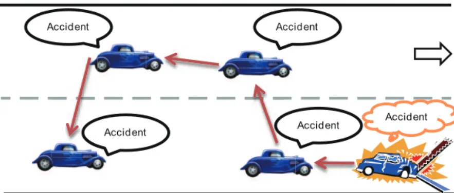
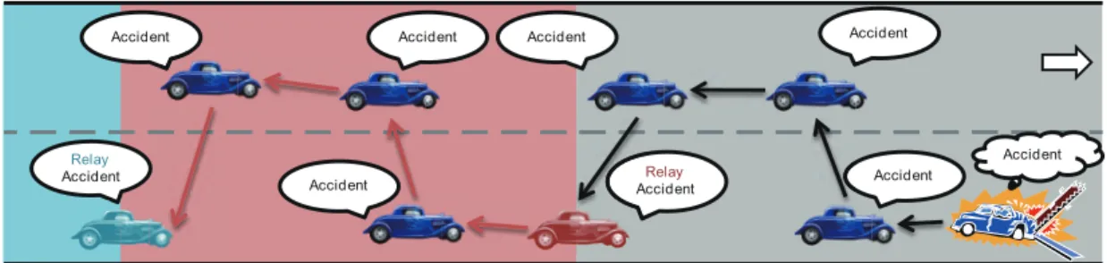
(17) Chapter 3. Collision-free Emergency Message Delivery Scheme 3.1 System Environments and Assumptions With collision-free emergency message delivery scheme proposed in this paper, it is assumed that each vehicle obtains its position based on a Global Positioning System (GPS) receiver [19] and gets the information of road width from RSUs. The network is assumed to be connected. Each vehicle is equipped with a DSRC device and an omnidirectional radio antennas of range R to connect with other vehicles. While travelling on the road, the vehicle uses a wireless transceiver to broadcast its current position through periodic beacon messages. Based on the neighboring vehicles’ beacon messages, the vehicle stores the neighbors’ information in its neighbor list for building a emergency message delivery path originated by itself. As shown in Fig. 3.1, it is further assumed that the vehicles drive along a section of straight road with a length L and a width W and are randomly deployed in the road with different speeds. If an accident. 8.
(18) Accident. Accident. Accident. Accident. Accident. Figure 3.1: The emergency message delivery.. occurs, the accident vehicle is able to transmit the emergency message to other vehicles on the road based with its emergency message delivery path. Based on DSRC’s standard, it provides several channels (seven 10 MHz channels in North America) for communications. In the proposed scheme, the emergency message can be transmitted in a reserved channel separated from the normal data channels.. 3.2 Protocol Design The emergency message delivery protocol consists of three phrases, i.e., beacon broadcast, the delivery path construction and the emergency message delivery. Initially, each vehicle periodically broadcasts a beacon message to its neighboring vehicles. Based on the information of the beacon message, the vehicle constructs its own emergency message delivery path. Once the vehicle is aware of an emergency situation, it delivers the emergency message for warning other vehicles based on its delivery path. In the beacon broadcast phrase, the beacon message contains the vehicle ID, the vehicle position and the vehicle speed. The vehicle then collects the information of beacon messages from its neighbors. While receiving a beacon message sent by a neighboring vehicle, the. 9.
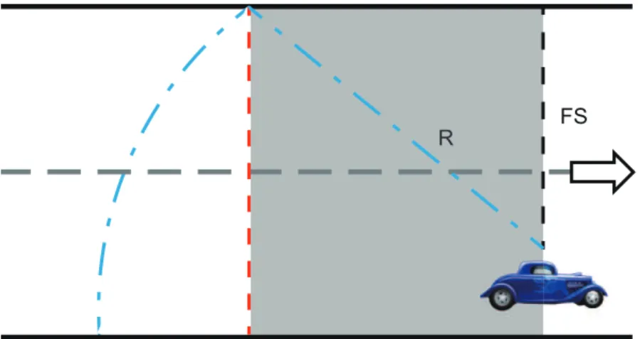
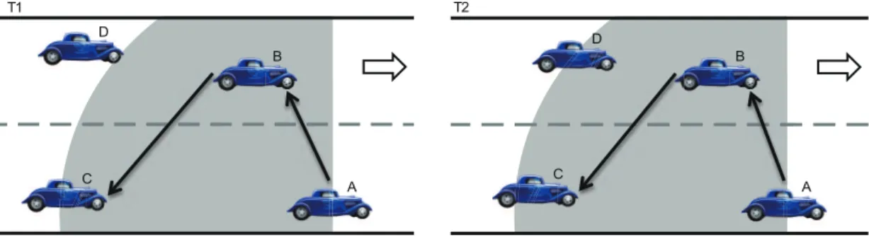
(19) FS R. Figure 3.2: Guaranteed range.. vehicle will check whether the neighboring vehicle’s position is within its guaranteed range (G) according to it position and the neighbor’s current position. The guaranteed range can be calculated as. G=. √. R2 − F S 2 ,. (3.1). where F S is the distance between the farther side of the road and the vehicle’s position. In general, the guaranteed range is always less than the default transmission range, i.e., G < R (see Fig. 3.2). The road will be partitioned into several segments to ensure that every vehicle can be notified of the occurrence of the accident. In fact, the proposed scheme allows the transmission range of each vehicle is different. That is, different transmission ranges will generate different guaranteed ranges. If the vehicle uses R as its guaranteed range, some vehicles may not be included in the emergency message delivery path. Fig. 3.3 illustrates an example of this issue. The vehicle A based on its delivery path (e.g., A → B → C) transmits the emergency message at T1 . However, the vehicle D is not within the transmission range of the vehicle A at T1 . At T2 ,. 10.
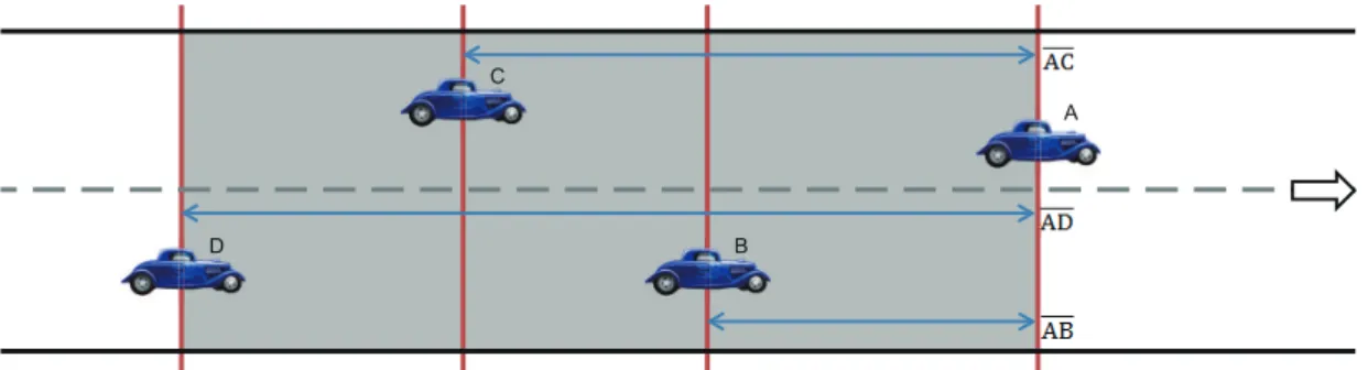
(20) T2. T1 D. D B. B. C. C. A. A. Figure 3.3: Problem of using the transmission range as the guaranteed range.. the vehicle D moving into the transmission range of the vehicle A but will not receive any emergency message form the vehicle A. In the delivery path construction phrase, if the neighboring vehicle is within the guaranteed range, the vehicle will check whether the neighbor’s vehicle ID exists in its neighbor list or not. If the neighbor list has the vehicle ID already, the vehicle updates the relative distance information between the neighbor and itself. If not, the vehicle computes the relative distance and then adds to its neighbor list. While updating or inserting a entry of the neighbor list, the neighbor list will be reordered based on the corresponding relative distance. The neighboring vehicle with the smallest relative distance will be the first order, and so on. Fig. 3.4 illustrates the relative distance between each A’s neighbor and the vehicle A. In Fig. 3.4, vehicles B, C, and D in the vehicle A’s guaranteed range. The vehicle A based on the current positions of B, C, and D to calculate the relative distances. The relative distances are shown as AB, AC and AD. Due to AB < AC < AD, the order of the neighbor list is A → B → C → D. Based on the order of the neighboring vehicles in its neighbor list, an emergency message delivery path can be established by the vehicle A. If two or more vehicles have the same relative distances, the vehicle A selects the vehicle which has the shorter residual time to deliver the emergency message earlier. The residual time of the vehicle V is calculated as. 11.
(21) C A. D. B. Figure 3.4: Relative distances between vehicles.. . residual time =. residual time =. |Vx−axis −(Ax−axis +G)| , Aspeed −Vspeed |Ax−axis −Vx−axis | , Vspeed −Aspeed. if A′ s speed > V ′ s speed (3.2) ′. ′. if V s speed < A s speed. Obviously, a vehicle with longer residual time means its relative speed is faster than other vehicles. Assume that the delivery path is an undirected graph G, it is obviously that the graph G follows the rule of the Hamiltonian path, i.e., a path which visits each node in the graph exactly once. Because the proposed scheme based on the Hamiltonian path to pass the emergency message, any vehicle will not receive the same message more than twice. So, there is no message collisions in the delivery process. In the emergency message delivery phrase, the accident vehicle sends the emergency message to other vehicles based on its delivery path. The emergency message contains the warning information (e.g., the accident type, location, time, and etc.) and the delivery path. Each vehicle in the sender’s delivery path receives the emergency message and then follows the delivery path to transmit the message to the next vehicle. If the vehicle V is the last vehicle of the path, then the vehicle V will become a relay and keep delivering the emergency message with its own delivery path. Algorithm 1 provides an overview of the proposed emergency message delivery algorithm. As shown in Fig. 3.5, the last vehicle of the delivery path in each. 12.
(22) Algorithm 1 Overview of the emergency message delivery algorithm 1: 2: 3: 4: 5: 6: 7: 8: 9: 10: 11: 12: 13: 14: 15: 16: 17: 18: 19: 20: 21: 22: 23: 24: 25: 26: 27: 28: 29: 30:. Each vehicle broadcast a periodical beacon message collect information from neighbors calculate the guaranteed range if the neighbor is within the guaranteed range then check whether the neighbor list already has this information or not if YES then update the relative distance reorder the neighbor list based on the relative distance end if else add as a new entry reorder the neighbor list based on the relative distance else Ignore the message end if Accident or relay vehicle if An accident occurs then transmit the emergency message to the next vehicle in its delivery path wait a predefined period if didn’t receive the ACK message then Act as a relay transmit the emergency message to the next vehicle in its delivery path end if end if Other vehicles if receive a emergency message then follow the sender’s path within the message to transmit the message to the next hop transmit the ACK message to the previous vehicle end if. guaranteed range will act as the relay to re-transmit the emergency message to other vehicles based on its delivery path. For preventing the break of the delivery path, each vehicle in the path receiving the emergency message will send an ACK message to the previous vehicle. That is, after the vehicle transmits the emergency message to the next vehicle, it will wait the ACK message sent by the next vehicle. If the vehicle do not receive the ACK message in a predefined period, the delivery path may be broken. The vehicle will act as a relay to re-transmit the emergency message to other vehicles based on its delivery path.. 13.
(23) Accident. Relay Accident. Accident. Accident. Accident. Accident R Relay Ac Accident. Accident. Figure 3.5: Relay vehicles.. 14. Accident.
(24) Chapter 4. Performance Evaluation The effectiveness of the proposed collision-free emergency message delivery scheme was evaluated by performing a series of numerical investigations using a commonly used network simulation software, the ns-2 simulator (version 2.31).. 4.1 Simulation Settings Five different schemes, i.e., ODAM [17], Slotted p-Persistence [18], Backbone [20], Direct Broadcast, and the proposed collision-free emergency message delivery scheme were implemented for performance comparisons. To analyze the performance of these protocols, the simulation environment considered the model of a length of 1000 m and a width of 200 m highway scenario. The vehicles randomly deployed in the simulation environment and each vehicle was assumed to has a homogeneous transmission range of 250 m. The simulations included different scenarios by varying the vehicle density (from 50 to 250 vehicles) and the vehicle speed (from 90 to 110 km/hr). To ensure the reliability of the simulation results, one hundred simulation runs were performed by using different initial vehicle deployments. In each 15.
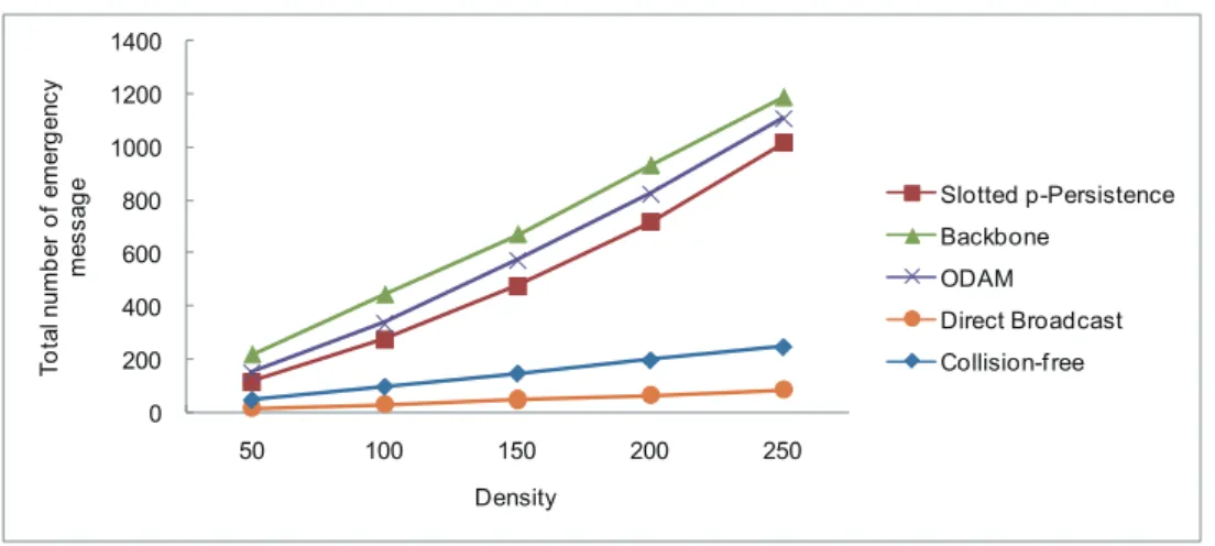
(25) Table 4.1: Simulation parameters Parameter Scenario model Transmission range Vehicles speed Vehicles density. Value(s) 1000 m x 200 m 250 m [90,110] km/h 50, 100, 150, 200, 250 vehicles. run, one accident vehicle transmitted a emergency message once. The parameters applied in the simulations are summarized in Table 4.1. Three metrics used in the simulations are shown as: 1. The total number of emergency messages is defined as the number of messages all vehicles received. 2. The average number of emergency message is defined as the average number of messages each vehicle received. 3. The message penetration rate is defined as the percentage of vehicles received the emergency message.. 4.2 Simulation Results Fig. 4.1 illustrates the total number of emergency messages the vehicles received on the road for Slotted p-Persistence, Backbone, ODAM, Direct Broadcast and the proposed collision-free emergency message delivery schemes. It is obviously that the total number emergency messages went up as the vehicle density increased. Because Direct Broadcast always produced message collisions at its first hop’s rebroadcast, its total number of emergency message packets was the least. ODAM generated more emergency messages than Slotted p-Persistence. This is because the design of Slotted p-Persistence is that each vehicle rebroadcasts the emergency message with probability p. With Backbone scheme, the number of backbone members are not fixed. 16.
(26) (i.e., depends on the vehicle deployment), so there may be a number of backbone members to rebroadcast the emergency message. Hence, more backbone members implies to transmitting more emergency messages. In our emergency message delivery method, each vehicle only received the emergency message once and only passed it to its next hop. The total number of emergency message of our scheme was less than that of ODAM, Slotted p-Persistence, and Backbone schemes. Because Direct Broadcast did not arrange any vehicle to receive the message in a vehicle’s transmission range, so even if using scheme to control the rebroadcast frequency, it is still probable that it will produce a considerable number of packets. Consequently, even the broadcast can provide advantage of fast transmission, but it is still easier to make collision of packet than other protocols. For this reason, many schemes are used to avoid broadcast storm problem by reducing rebroadcast frequency. For instance, the backbone method to appoints some specific vehicles to broadcast warning message, but vehicles still receive the same message again and again. In the other hand, ODAM and slotted p-persistence broadcasting scheme them to design the farthest vehicle to rebroadcast the alarm message, but in sometime they still have the possibility of packet collision in order to two vehicle are parallel to each other. Fig. 4.2 depicts the average number of emergency messages each vehicle received for all schemes. The average number of emergency messages of Backbone, ODAM, and Slotted p-Persistence schemes were about 4.5, 3.9, and 3 times, respectively, more than our proposed scheme. Backbone, ODAM, Slotted p-Persistence schemes still had the possibility of message collisions. When the vehicle density increased, the number of rebroadcast increased as well. With our method, the average number of emergency messages was 1. In this way, the proposed scheme can avoid to cause message collisions.. 17.
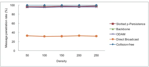
(27) Total number of emergency message. 1400 1200 1000 Slotted p-Persistence. 800. Backbone. 600. ODAM 400. Direct Broadcast. 200. Collision-f ree. 0 50. 100. 150. 200. 250. Density. Figure 4.1: Total number of emergency messages vs. vehicle density.. Average number of emergency message. 5 4 3. Slotted p-Persistence Backbone. 2. ODAM Direct Broadcast. 1. Collision-f ree 0 50. 100. 150. 200. 250. Density. Figure 4.2: Average number of emergency messages vs. vehicle density.. Fig. 4.3 describes the message penetration rate of all schemes. The result of Direct Broadcast only had about 30% of message penetration rate. Due to the collision issue, ODAM, and Slotted p-Persistence had about 96% of message penetration rate. With Backbone scheme, the backbone members used the rebroadcast technique to notify their neighbors. Therefore, the message penetration rate of Backbone is similar to that of the proposed scheme, i.e., providing 100% of message penetration rate.. 18.
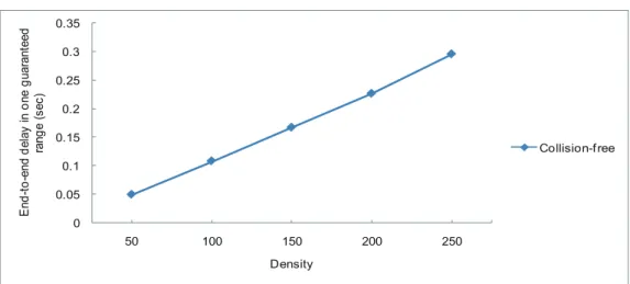
(28) Message penetration rate (%). 100 80 60. Slotted p-Persistence Backbone. 40. ODAM Direct Broadcast. 20. Collision-f ree 0 50. 100. 150. 200. 250. Density. Figure 4.3: Message penetration rate vs. vehicle density.. Fig. 4.4 depicts the end-to-end delay of all schemes. Although the proposed delivery mechanism spent more time than other schemes on delivering the emergency message, the proposed mechanism can reduce the number of emergency message and provide 100% of message penetration rate. ODAM and Slotted p-Persistence transmitted the emergency message faster, but they have to depend on the periodic rebroadcast to reach higher message penetration rate. Each rebroadcast may increase the possibility of collisions. Fig. 4.5 illustrates the endto-end delay in one guaranteed range for the proposed scheme. The proposed scheme only consumed less than 0.3 second to notify the vehicles in the guaranteed range. Based on the result in Fig. 4.5, suppose that a vehicle locates at the border of the guaranteed range. The vehicle with highest speed moves forward about 9.16 m after receiving the emergency message (about 0.3 second). Because the smallest guaranteed range is about 229 m, the vehicle will not overtake the accident vehicle without being notify of the emergency.. 19.
(29) End-to-end delay (sec). 1.4 1.2 1 Slotted p-Persistence. 0.8. Backbone. 0.6. ODAM 0.4. Direct Broadcast. 0.2. Collision-f ree. 0 50. 100. 150. 200. 250. Density. End-to-end delay in one guaranteed range (sec). Figure 4.4: End-to-end delay vs. vehicle density.. 0.35 0.3 0.25 0.2 0.15. Collision-f ree. 0.1 0.05 0 50. 100. 150. 200. 250. Density. Figure 4.5: End-to-end delay in one guaranteed range vs. vehicle density.. 20.
(30) Chapter 5. Conclusion and Future Work In this thesis, the collision-free emergency message delivery scheme is proposed for VANETs. Based on neighbors beacon information, each vehicle can create a Hamiltonian path to deliver emergency messages to its neighbors. The validity of the proposed approach has been confirmed by performing a series of simulations using the ns-2 network simulator. The performance of Collision-free Emergency Message Delivery scheme has been compared to Direct Broadcast, Backbone, ODAM, and Slotted p-Persistence schemes. The results have shown that the proposed scheme does not need to periodically rebroadcast to increase the message penetration rate. With the average or total number of emergency messages, the proposed scheme is lower than other schemes. Although the proposed scheme spends more time on delivering emergency messages, it only takes 0.3 second to notify all of the vehicles in the first guaranteed range. Therefore, the proposed scheme provides an effective way to deliver the emergency message and avoids message collisions. Moreover, the proposed scheme is insensitive to the changes in the vehicle speed and the vehicle density.. 21.
(31) The future work will investigate the performance of the proposed emergency message delivery scheme in realistic environments and consider different kinds of scenarios.. 22.
(32) References [1] Taiwan Area National Freeway Bureau http://www.freeway.gov.tw/Publish.aspx?cnid=1556.. MOTC.. URL. [2] D. Jiang, V. Taliwal, A. Meier, W. Holfelder, and R. Herrtwich, “Design of 5.9 GHz DSRC-based vehicular safety communication,” IEEE Wireless Communications, vol. 13, no. 5, pp. 36–43, Oct. 2006. [3] R. Bishop, “A survey of intelligent vehicle applications worldwide,” Proceedings of the IEEE Intelligent Vehicles Symposium, pp. 25–30, Oct. 2000. [4] T. ElBatt, S. K. Goel, G. Holland, H. Krishnan, and J. Parikh, “Cooperative collision warning using dedicated short range wireless communications,” Proceedings of the 3rd ACM international workshop on Vehicular ad hoc network VANET, pp. 1–9, Sep. 2006. [5] J. Yin, T. ElBatt, G. Yeung, B. Ryu, S. Habermas, H. Krishnan, and T. Talty,, “Performance evaluation of safety applications over DSRC vehicular ad hoc networks,” Proceedings of the 1st ACM international workshop on Vehicular ad hoc networks, pp. 1–9, Sep. 2004. [6] W. Chen and S. Cai, “Ad Hoc Peer-to-Peer Network Architecture for Vehicle Safety Communications,” IEEE Communications Magazine, vol. 43, no. 4, pp. 100–107, Apr. 2005. [7] C. J. Merlin and W. B. Heinzelman, “A study of safety applications in vehicular networks,” Proceedings of the Mobile Ad-hoc and Sensor Systems Conference, pp. 7–10, 2005. [8] H. Hartenstein and K. P. Laberteaux, “A tutorial survey on vehicular ad hoc networks,” IEEE Communications Magazine, vol. 46, no. 6, pp. 164–171, Jun. 2008. [9] S. Yousefi, M. S. Mousavi, and M. Fathy, “Vehicular Ad Hoc Networks (VANETs): Challenges and Perspectives,” Proceedings of International Conference on ITS Telecommunications, pp. 761–766, Jun. 2006. [10] F. Li and Y. Wang, “Routing in Vehicular Ad Hoc Networks: A Survey,” IEEE Vehicular Technology Magazine, vol. 2, no. 2, pp. 12–22, Jun. 2007. [11] E. Royer and C.-K. Toh, “A Review of Current Routing Protocols for Ad Hoc Mobile Wireless Networks,” IEEE Personal Communications, vol. 6, no. 2, pp. 46–55, Apr. 1999. [12] S.-Y. Ni, Y.-C. Tseng, Y.-S. Chen, and J.-P. Sheu, “The Broadcast Storm Problem in a Mobile Ad Hoc Network,” Proceedings of MOBICOM, pp. 151–162, 1999.. 23.
(33) [13] X. Yang, J. Liu, F. Zhao, and N. Vaidya, “A Vehicle to Vehicle Communication Protocol for Cooperative Collision Warning,” Proceedings of ACM MobiQuitous, pp. 121–130, Aug. 2004. [14] X. Qing, M. Tony, K. Jeff, and S. Raja, “Vehicle-to-Vehicle Safety Messaging in DSRC,” Proceedings of the 1st ACM international workshop on Vehicular ad hoc networks, pp. 19– 28, Oct. 2004. [15] N. M. Rabadi and S. M. Mahmud, “Performance Evaluation of IEEE 802.11a MAC Protocol for Vehicle Intersection Collision Avoidance System,” Proceedings of IEEE Consumer Communications and Networking Conference, pp. 54–58, Jan. 2007. [16] The Network Simulator - ns-2. URL http://www.isi.edu/nsnam/ns/. [17] A. Benslimane, “Optimized Dissemination of Alarm Messages in Vehicular Ad-Hoc Networks (VANET),” Proceedings of the 7th IEEE International Conference HSNMC, pp. 655–666, Jun. 2004. [18] N. Wisitpongphan, O. K. Tonguz, J. S. Parikh, P. Mudalige, F. Bai, and V. Sadekar, “Broadcast Storm Mitigation Techniques In Vehicular Ad Hoc Networks,” IEEE Wireless Communications, vol. 14, no. 6, pp. 84–94, Dec. 2007. [19] B. Hofmann-Wellenhof, H. Lichtenegger, and J. Collins, Global Positioning System: Theory and Practice. Springer-Verlag, 1997. [20] L. Bononi and M. D. Felice, “A Cross Layered MAC and Clustering Scheme for Efficient Broadcast in VANETs,” Proceedings of the IEEE International Conference on Mobile Adhoc and Sensor Systems, pp. 1–8, 2007.. 24.
(34) Vita Wei-Pu He was born on February 9, 1987, in Kaohsiung, Taiwan. He received the B.S. degree in Computer Science & Information Engineering from National Pingtung Institute of Commerce, Taiwan, in 2009. He enrolled at the National Pingtung Institute of Commerce as a master student in Computer Science & Information Engineering in September 2009. He worked as a research assistant for Professor Chia-Ho Ou and concentrated his research on vehicular ad hoc networks.. 25.
(35)
數據
+6

相關文件
Central lab was done for toxicity check yet the sampling time is not within the allowable range as stated in protocol. Central lab data was reviewed prior to
2.8 The principles for short-term change are building on the strengths of teachers and schools to develop incremental change, and enhancing interactive collaboration to
NETs can contribute to the continuing discussion in Hong Kong about the teaching and learning of English by joining local teachers in inter-school staff development initiatives..
Courtesy: Ned Wright’s Cosmology Page Burles, Nolette & Turner, 1999?. Total Mass Density
National Central University (NCU) welcomes students with a range of qualifications from all over the world. Eligibility requirements vary according to
• Flux ratios and gravitational imaging can probe the subhalo mass function down to 1e7 solar masses. and thus help rule out (or
2-1 註冊為會員後您便有了個別的”my iF”帳戶。完成註冊後請點選左方 Register entry (直接登入 my iF 則直接進入下方畫面),即可選擇目前開放可供參賽的獎項,找到iF STUDENT
專案執 行團隊
