Development of a Systematic Scheme for Direct Driven Slotless Tubular Linear Generator Design
Cheng-Tsung Liu
Senior Member, IEEE National Sun Yat-Sen University
70 Lien-hai Road Kaohsiung, TAIWAN 80424
Hsin-Nan Lin
National Sun Yat-Sen University 70 Lien-hai Road Kaohsiung, TAIWAN 80424 [email protected]
Abstract – This paper is aimed to present the systematic design scheme of a direct driven slotless tubular linear generator for renewable energy retraction. To reduce operational cogging and increase energy conversion efficiency, the generator stator is equipped with slotless concentrated annular multiphase windings and its mover is encircled by quasi-Halbach arranged permanent magnets. By systematic comparisons and classifications, the preliminary design and operational specifications of supplying maximum flux that can link the stator windings are fulfilled by setting appropriate factor level combinations from the Taguchi’s method. Along with the stator winding selections, potential energy generations from the proposed slotless tubular linear generator can then be estimated.
Verified by three-dimensional finite element analyses, the constructed machine prototype can show its adequacy for the operational and design requirements.
Index Terms—Halbach, linear generator, permanent magnet, Taguchi’s method, tubular.
I. INTRODUCTION
The ever increasing demands for generating electricity from various carbon-free renewable energy sources have drawn the efforts of developing appropriate mechanical and electrical conversion systems that can fulfill these special operational requirements. A tubular linear generator (TLG) [1], with slotless stator windings and quasi-Halbach mover permanent magnet (PM) arrangement [2] that can operate in reciprocating manner to incorporate with those reciprocating energy extraction mechanisms, will be reported in this paper.
Though the design concepts of tubular linear electric machines are quite common [3], detailed electromagnetic characteristics will be required for the operational performance evaluation. In addition, with specific operational requirements and constraints, a compact and systematic scheme that can assist to design the most appropriate slotless tubular linear generator (STLG) is certainly preferred. Since most of the designs on electric machines are conducted from empirical basis, the idea of properly selecting sets of parameters that can supply the optimal combinations with desired performance as commonly adopted in the quality engineering, namely as Taguchi’s method [4], is introduced to perform the relative machine parameter selections and performance assessments.
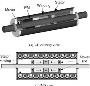
II. THE SLOTLESS TUBULAR LINEAR GENERATOR Fig. 1 shows the conceptual structure of a STLG. The main flux direction in the mover is determined by the magnetization of permanent magnets and the generated voltage level is dominated by the interactions between stator windings and mover fluxes. For those STLGs with traditional axial and radial magnetizations, ferromagnetic materials are generally required to guide the desired flux paths. Inevitably, the operational temperatures and the induced eddy currents in these materials will produce extra system power losses and also degrade the performance of mover PMs. For construction simplicity and cost reduction, by adopting the quasi-Halbach PM arrays onto the mover have been selected to fulfill the STLG mover structure requirements [5], [6]. Due to the inherent flux guidance characteristics of Halbach array, there is more flexibility in the selections of machine axial rod materials.
For such a STLG structure, it is addressed that the interaction rates and directions among stator windings and mover fluxes will determine the generator voltage supplies.
Since this machine is generally designed for direct driven, the maximum mover reciprocating speed is predetermined from
(a) 3-D cutaway view.
(b) 2-D view.
Fig. 1. Conceptual structure of a slotless tubular linear generator with quasi-Halbach arranged permanent magnets on the mover.
PEDS2009
the mechanical driven source. It is thus cleared that the axial- directional magnetic fluxes that can pass through the stator windings will be the dominant factor. Proper selections on the combinations of stator and mover physical dimensions to maximize the fluxes at certain operational constraints are the desired design objectives.
As the induced voltage will be proportional to the total equivalent fluxes that are linking the stator windings, a general design guidance is to seek the maximum number of turns that can be wound on the machine stator. However, with limited space, thinner wires will supply higher system open- circuit voltages but the total stator winding resistances and thus losses will also be increased. Based on the desired operational voltage level, merit and demerit among winding turns and operational performance are also required to be thoroughly assessed in the design.
Due to the asymmetrical stator winding arrangements and mechanical end effects, the induced voltages will be unbalanced in the stator three-phase windings. Besides, with position-dependent operational flux linkages, harmonic distortions on the generated voltages will also affect the operations of such direct driven STLG. Proper performance indices on the voltage waveforms at both the generator AC side and the regulated DC side must be incorporated in the determinations of adequate machine parameters.
III. OPTIMAL DESIGN OF THE GENERATOR A. Problem Definitions
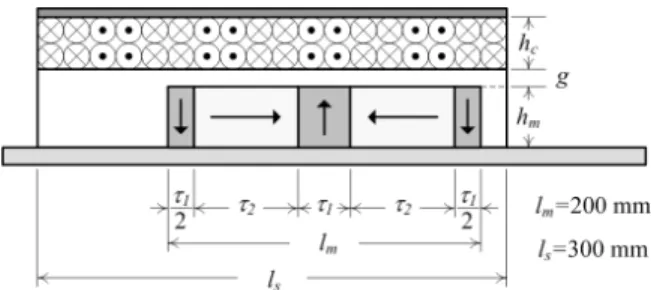
Fig. 2 shows the related design parameters of the STLG.
The objective is to design a laboratory-class generator prototype that is capable of supplying 1/2 hp electricity and its regulated DC-side voltage must exceed 60 V. By selecting some of the key parameters as optimization factors and assigning every factor with three feasible levels, the classified factor-level combination for design are illustrated in Table I.
To find the optimal parameters from these factor-level combinations, the operational objective of achieving maximum axial-directional magnetic fluxes that can pass through the stator windings along with certain constraints are generally specified as:
: ( , , ) ( , , , )
: 0 , 0 ,
m S m
s m s m a c
Maximize r z d B r z d d s
Subject to z l d l l r r r
⎧ = ⋅
⎪⎨
≤ ≤ ≤ ≤ − ≤ <
⎪⎩
∫
G Gφ
φ
φ θ
(1)
where φ is the axial-directional flux passing through the stator winding and BJG
is the flux density inside the generator.
Though there are 34=81 possible combinations of these factors and levels, by introducing an orthogonal array representing the parameter combination space that is allowable in the design, a systematic and efficient search of the optimal factor-level combinations can be done. This scheme is based on the Taguchi’s method as commonly used in quality engineering related designs [4]. The corresponding L9(34) matrix as shown in Table II is then designed for performing the experiments. The desired indices for performance evaluations, axial-directional magnetic fluxes that can passing through the stator windings of the STLG, can then be calculated by using three-dimensional (3-D) finite element analyses (FEA) [7]. As magnetic fluxes are dependent on the mover positions, with a stable reciprocating operation, the exhibited magnetic fluxes and the total harmonic distortion (THD) can be expressed in the forms:
0 1
( , , m) ncos(2 m n) and
n m
r z d F F nd
φ l
φ ∞ π θ
=
= +
∑
− (2a)1 2
THD 1 ( n),
n
F F
∞
=
=
∑
(2b)where Fi is the magnitude of axial-directional flux passing through the stator winding at the corresponding ith space harmonic.
Fig. 2. Related physical parameters of the slotless tubular linear generator for optimization selections.
TABLEI
DESIGN FACTOR AND LEVEL CLASSIFICATIONS OF THE SLOTLESS TUBULAR
LINEAR GENERATOR
Design factor Level 1 Level 2 Level 3
A: τ1 42 mm 33.4 mm 25 mm
B: hm 10 mm 11 mm 12 mm
C: hc+g 9 mm 10 mm 11 mm
D: hc/g 1.57 1.25 1.0
TABLEII
ORTHOGONAL ARRAY FOR CONDUCTING TAGUCHI’S EXPERIMENTS
Experiment Factor-Level combination
A B C D
1 1 1 1 1
2 1 2 2 2
3 1 3 3 3
4 2 1 2 3
5 2 2 3 1
6 2 3 1 2
7 3 1 3 2
8 3 2 1 3
9 3 3 2 1
PEDS2009
B. Optimization Specifications
From the above two index definitions, by taking either the fundamental component or the THD as the target, different optimization designs will be obtained. By using the signal-to- noise ratio (SNR) at two distinct objectives as:
Smaller the better, 2
1
10 log(1 n ) and
STB i
i
SNR y
n =
= −
∑
(3a)Larger the better, 2
1
1 1
10 log( n )
LTB
i i
SNR n = y
= −
∑
, (3b)where n is the number of experiments and yi is the experimental result obtained from the ith experiment.
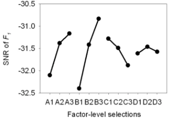
It is apparent that SNRLTB must be picked for the flux fundamental component F1, and SNRSTB must be picked for the flux THD. By taking the averaged effects contributed from individual factor-level, the analyzed results are illustrated in Fig. 3. From these preliminary classified investigations, the resultant optimal combination for providing maximized F1 is A3-B3-C1-D2, and for exhibiting minimized THD is A2-B3-C3-D1. Therefore, to provide optimal system design guidance, compromised selections of
the possible factor-level combinations are required. Since there are three levels for every of the design factor, a systematic analysis of variance (ANOVA) scheme that introduces the sum of squares is defined as:
3
, 1
3 ( )
i ij i all
j
SS m m
=
=
∑
− , (4)where i is the corresponding design factor, mij is the averaged SNR of factor i at the jth level, and mi,all is the averaged SNR of factor i at all three levels.
For evaluating the impacts on the two optimization objectives, contributions from those design factors are summarized in Table III and their relative percentages are depicted in Fig. 4. By selecting the dominant factor-level combinations from Figs. 3 and 4, it can be seen that the corresponding level for the individual factor should be:
Factor A: THD Æ A2, Factor B: F1 Æ B3, Factor C: F1 Æ C1, and Factor D: THD Æ D1.
From this systematic ANOVA, the individual dominant factor-level that will affect the machine design can then be determined. Thus the combination that can provide the optimized solution about the STLG structure, with its axial- directional flux as the design objective, will be A2-B3-C1-D1.
(a) Averaged effects contributed from individual factor-level for maximizing the SNR of fundamental flux component.
(b) Averaged effects contributed from individual factor-level for minimizing the SNR of total harmonic distortion.
Fig. 3. The signal-to-noise ratios of the STLG at different design objectives with various factor-levels.
TABLEIII
IMPACTS OF DESIGN FACTORS ON OPTIMIZATION OBJECTIVES
Design factor
F1 THD
SSi Contribution SSi Contribution A 1.4417 24.88% 0.1560 27.04%
B 3.7606 64.90% 0.2662 46.14%
C 0.5551 9.58% 0.0057 1.00%
D 0.0368 0.64% 0.1490 25.82%
Total 5.7942 100% 0.5769 100%
Fig. 4. Contributions of design factors by ANOVA.
PEDS2009
C. Stator Winding Selections
Based on the operational requirements, the generated 3- phase AC energies from STLG will be rectified to DC for further utilization or storage. The generator stator windings are thus designed based on the desired DC-side voltage level.
For example, at an input speed of 3 m/s, if the objective DC voltage is 80 V with an adjustable range of 10%,± a preliminary investigation shows both of the above devised combinations, A3-B3-C1-D2 and A2-B3-C3-D1, can achieve this voltage level by using the AWG18 or thinner wires.
However, with their different physical dimensions, the compromised one with combination of A2-B3-C1-D1 requires less winding turns and thus smaller resistances, and better electric characteristics can then be expected.
By using the same winding sizes (AWG19), a further comparison is provided in Fig. 5. With the resultant regulated DC-side voltages of the STLG obtained from two factor-level combinations, clearly it can be seen that the generator with settings obtained by systematic design (A2-B3-C1-D1) will not only satisfy the DC-side voltage requirement but also supply an about 30% higher voltage than those obtained from the initial empirical design (A3-B1-C3-D2).
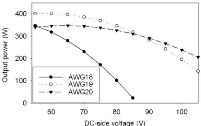
From the above investigations, it is clear that the selections of winding sizes will greatly affect the performance of designed STLG based on different operational specifications. By assembling the generator stator windings using different wires, further detailed comparisons have also been performed based on the same structural design (A2-B3-C1-D1). Fig. 6 shows the output no-load regulated DC-side voltages of the STLG at different mechanical input speeds. With the same geometrical space, it is certain that more turns can be wound by using thinner wires and consequently higher voltages will be induced. In addition to the no-load performance, the output power capabilities of the STLG with different stator windings have also been investigated as shown in Figs. 7 and 8. From these illustrations, possibility of selecting the AWG18 wire can be eliminated due to the relatively poor power output characteristics. While from the two intersection points shown
on the power-speed and power-voltage characteristics, selections of the other two types of wires for the STLG stator winding constructions are clearly determined by the objective operational speed and voltage levels.
Fig. 6. No-load DC-side voltages of the STLG with various driven speeds and stator windings.
Fig. 7. Output power capabilities of the STLG at a fixed speed of 3 m/s with various DC-side voltages and stator windings.
Fig. 8. Output power capabilities of the STLG at a fixed DC-side voltage of 84 V with various driven speeds and stator windings.
Fig. 5. Illustrations of the rectified DC-side voltages of the STLG with two factor-level combinations.
PEDS2009
IV. DESIGN CONFIRMATIONS
The systematic design scheme as provided in the preceding section showed that the A2-B3-C1-D1 structure combined with AWG19 stator windings of the STLG can meet the desired design objective. By using the same wires for stator winding constructions, further comparison investigations on the other structural parameter combinations will be conducted to validate the optimization scheme. These structures are the empirical design (A3-B1-C3-D2), the maximized fundamental flux design (A3-B3-C1-D2), the minimized total harmonic distortion design (A2-B3-C3-D1), and the optimized design (A2-B3-C1-D1) through the proposed systematic scheme.
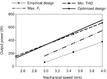
As illustrated in Figs. 9 and 10, the output power characteristics of the STLG at various operational specifications are provided for comparisons. It is evident that neither of the one based on empirical or maximized fundamental flux design will exhibit competitive performance.
Though the one based on minimization of total harmonic distortion will supply larger power output at certain operational ranges (higher output voltages or lower input speeds), the relatively larger power losses in these conditions also downgrade the possibility of selecting such structure. At the rated input mechanical speed of 3 m/s, the STLG with optimized design will supply electric power outputs larger than 340 W if the regulated DC-side voltages are smaller than 84 V. Or if this terminal voltage is fixed, the output powers will be larger than 340 W with higher mechanical speed inputs. The design objectives based on the optimized structure can thus certainly be confirmed from such validations.
V. CONCLUSIONS
A systematic design scheme of a direct driven slotless tubular linear generator for renewable energy retraction has been presented. Based on Taguchi’s method, systematic comparisons and classifications were performed to identify the optimal machine structure for the design objectives.
Appropriate stator windings, by thoroughly estimating the potential power generations from the proposed STLG, can then be selected. From the developed scheme and the constructed machine prototype, adequate guidance for designing the related renewable energy retraction mechanisms has successfully demonstrated.
ACKNOWLEDGMENT
The authors want to express their appreciations to Mr. C.- H. Tu for his assistance on the STLG prototype construction.
Financial supports from the National Science Council, Taiwan, R.O.C. under contract NSC 96-2221-E-110-099- MY3 are also to be acknowledged.
REFERENCES
[1] P. Cancelliere, F. Marignetti, V. Delli Colli, R. Di Stefano, and M.
Scarano, “A tubular generator for marine energy direct drive applications,” Int. Conf. Elec. Mach. and Drives, 2005 IEEE, 15-18 May 2005, pp. 1473 – 1478.
[2] S.-M. Jang, J.-Y. Choi, H.-W. Cho, and S.-H. Lee, “Thrust analysis and measurements of tubular linear actuator with cylindrical Halbach array,” IEEE Trans. Magn., vol. 41, no. 5, pp. 2028-2031, May 2005.
[3] J. Wang, G. W. Jewell, and D. Howe, “A general framework for the analysis and design of tubular linear permanent magnet machines,”
IEEE Trans. Magn., vol. 35, no. 3, Pt. 2, pp. 1986-2000, May 1999.
[4] P. J. Ross, Taguchi Techniques for Quality Engineering: Loss Function, Orthogonal Experiments, Parameter and Tolerance Design, McGraw-Hill, New York, U.S.A., 1996.
[5] J. Wang and D. Howe, “Tubular modular permanent-magnet machines equipped with quasi-Halbach magnetized magnets—Part I: magnetic field distribution, EMF, and thrust force,” IEEE Trans. Magn., vol. 41, no. 9, pp. 2470-2478, Sept. 2005.
[6] J. Wang and D. Howe, “Tubular modular permanent-magnet machines equipped with quasi-Halbach magnetized magnets—Part II: armature reaction and design optimization,” IEEE Trans. Magn., vol. 41, no. 9, pp. 2479-2489, Sept. 2005.
[7] COMSOL AB, COMSOL Multiphysics User’s Guide, Version 3.4, Stockholm, Sweden, 2007.
Fig. 9. Output power capabilities of the STLG at a fixed speed of 3 m/s with various DC-side voltages and optimization objectives.
Fig. 10. Output power capabilities of the STLG at a fixed DC-side voltage of 84 V with various driven speeds and optimization objectives.
PEDS2009