國 立 交 通 大 學
電機資訊學院 資訊學程
碩 士 論 文
泛歐數位式行動電話與網際網路電話以
智慧型網路為基礎之同步振鈴服務
An IN-based One Number Parallel Ring Service to
GSM and IP Phones
指導教授:張明峰 教授
研 究 生:郭晉碩
泛歐數位式行動電話與網際網路電話以
智慧型網路為基礎之同步振鈴服務
An IN-based One Number Parallel Ring Service to
GSM and IP Phones
研 究 生: 郭晉碩 Student: Chin-Shuo Kuo
指導教授: 張明峰教授
Advisors: Prof. Ming-Feng Chang
國 立 交 通 大 學
電機資訊學院 資訊學程
碩 士 論 文
A Thesis Submitted to Degree Program of Electrical Engineering and Computer Science College of Electrical Engineering and Computer Science
National Chiao Tung University in Partial Fulfillment of the Requirements
for the Degree of Master of Science In Computer Science
March 2005
Hsinchu, Taiwan, Republic of China
泛歐數位式行動電話與網際網路電話以
智慧型網路為基礎之同步振鈴服務
學生:郭晉碩
指導教授:張明峰 博士
國立交通大學電機資訊學院資訊學程碩士班
中文摘要
近期電信網路的發展,已經朝向各種類型網路統合的趨勢。因此,如何將幾種電話 網路整合,存在有許多的議題可以探討。各個不同的網路,共同使用同一號碼的想法, 符合簡化的潮流。本文提到的服務方法,不論在何種性質的網路中只要用一個號碼即可 聯絡到對方,這樣的服務尤其適合用戶在國外,當沒有網際網路電話門號的服務時,就 可以用此服務在國外撥接電話,而不需負擔昂貴的行動電話國際漫遊費用。 現有技術諸如網際網路電話號碼對應技術(ENUM),雖然可以讓 GSM 電話用戶撥打 到網路電話,但仍存在許多問題。因此本文設計了幾項機制,並以平行呼叫服務(Parallel Ring Service)實作,這樣就可以在現有行動電話網路中整合網路電話,讓使用網路電話 (尤其是無線網路電話)不需再申請網路電話專屬號碼,也符合單一使用者使用單一隨身 碼的人性化設計原則。System), 版本 R4,均尚未進入真正全封包傳輸網路 (UMTS 第五版) 的時代,與網際 網路電話的流暢互動仍不可行。而第二代泛歐數位式行動電話系統服務的使用者廣大, 為因應網路電話使用者快速膨脹的趨勢,必須把握市場最適當的進入時間。透過本論文 所提出的架構,就可以在現存 GSM 服務業者網路中真正實作可快速上線的多網電話服 務。
An IN-based One Number Parallel Ring Service to
GSM and IP Phones
Student: Chin-Shuo Kuo Advisor: Dr. Ming-Feng Chang
Department of Degree Program of Electrical Engineering & Computer Science
- Master Program of Computer Science
National Chiao Tung University
Abstract
The trend of the recent telecommunication network development is integrating different networks. Many issues still need to be investigated in this domain. The concept of using only one number for each user among different networks fits the current trend of integrating networks with a simpler human operation method. In the service model presented in this thesis, a user can be reached by dialing the user’s GSM phone number, no matter what networks the user is on. For example, when we go abroad, we can a GSM terminating call from an IP phone without having to pay expensive international mobile roaming fee.
Using current technologies, such as ENUM (Mapping an E.164 number to URI using DNS) and Session Initiation Protocol (SIP), a call can be initiated from GSM networks and terminated on the Internet. But, ENUM still has some limitations that hinder the GSM and
IP network integration. In this thesis, we present an IN-based parallel ring service to integrate the service for GSM and IP telephony. A GSM subscriber doesn’t need to apply another IP phone number and can enjoy the one personal number service in both the GSM and IP networks.
3G (3rd generation) All-IP (version R5) network is still not mature in 2005. Thus, the smooth interaction between GSM and IP Telephony still faces a lot of difficulties. With the trend of fast growth of the users in IP-Networks, we present a simple solution that meets the time-to-market requirement and to provide parallel ring service to GSM and IP networks.
誌 謝
能順利完成此篇論文,最要感謝指導老師張明峰教授一年半以來費心的指導。於 受業間,老師的耐心指正和灌輸我正確的為人處事方法,亦是讓我受益良多。在撰寫 論文期間,感謝孟達、文凱和毓麒三位先學幫忙快速認識學校資源與適應環境,感謝 在職班同學朝坤與貴榮的相互砥礪。也要感謝網際網路電話實驗室的同學們,榮泰、 其範、瑋晟和建彰以及學弟們的支持和鼓勵。另外,由衷的感謝我的摯愛,也就是我 的太太,百吟,從大學認識到進入研究所無怨無悔默默的支持我,並全力照顧家庭, 讓我無後顧之憂,是我心靈上最大的支柱。最後要感謝兩位女兒育伶與貞伶的陪伴與 可愛的撒嬌,讓我在工作與課業雙重壓力之下能快速的解壓。 最後,原將此篇論文獻給我所愛的家人與好友。Table of Contents
中文摘要 ...iii
Abstract... v
誌 謝 ...vii
Table of Contents ...viii
List of Figures ...xi
List of Tables ...xii
Chapter 1 Introduction... 1
1.1 The interworking between the PSTN and IP networks using ENUM ... 4
1.2 The advantage of one-number parallel ring service ... 5
1.3 Why ENUM solution not suitable? ... 6
1.4 Motivations, advantages and innovations of this thesis ... 7
Chapter 2 Networks, ENUM and Parallel Ring Service ... 9
2.1 GSM mobile call termination routing... 9
2.2 IN based GSM service... 10
2.2.1 Basic IN service model... 10
2.2.2 IN based GSM service with CAMEL... 11
2.2.3 CAMEL T-CSI trigger and MT user status... 12
2.2.4 An example of signaling procedures using CAMEL... 15
2.3 SIP ... 17
2.4 SIP routing ... 20
2.5 GSM and SIP interworking ... 21
2.6 ENUM ... 24
2.7.2 Parallel ring service using service node ... 27
Chapter 3 An IN and Service Node Integrated Parallel Ring Service to Mobile Phones and IP Phones System Design ... 29
3.1 Parallel Ring Service to GSM and IP Phone ... 29
3.2 IN and service node integrated solution ... 31
3.3 SIP URI bearer in SS7 network design... 33
3.3.1 Q.763 (ISUP) parameters overview... 33
3.3.2 SS7 Q.763 parameter extend for the SIP URI ... 36
3.3.3 Deliver the Q.763 extension parameter in the GSM network ... 39
3.4 SIP location database in SS7 network ... 40
3.4.1 SIP location and status database designed for SCP ... 40
3.4.2 Database requirement and schema ... 41
3.4.3 SIP register and update ... 43
3.4.4 Mapping the MSISDN and SIP URI ... 44
3.5 Use SCP in the GSM and IP networks ... 45
3.6 Service logic design... 47
3.6.1 ISUP and SIP protocols mapping ... 47
3.6.2 Scenarios examples ... 49
Chapter 4 Implementation ... 52
4.1 System setup ...52
4.2 Scenarios... 53
4.2.1 Scenario 1: mobile phone and IP phone are online ... 53
4.2.2 Scenario 2: mobile phone online only ... 54
4.2.3 Scenario 3: IP phone online only... 54
4.2.4 Scenario 4: IP phone call to IP phone with generic MSISDN... 55
Chapter 5 Conclusions... 58 Reference ... 59
List of Figures
Figure 1-1: PSTN-IP number mapping ... 5
Figure 2-1: GSM Mobile Call Termination Routing Procedure... 9
Figure 2-2: Architecture of the GSM Intelligent Network system...11
Figure 2-3: CAMEL Architecture (Phase 2) ... 13
Figure 2-4: IN CAMEL procedure ... 14
Figure 2-5: Mobile Originating Calls... 15
Figure 2-6: Mobile Terminating Calls... 16
Figure 2-7: Do-Not-Disturb Service ... 17
Figure 2-8: SIP Proxy Operation... 20
Figure 2-9: SIP Redirect Operation... 21
Figure 2-10: SIP to GSM Call ... 22
Figure 2-11: GSM to SIP Call ... 23
Figure 2-12: ENUM Mechanism Used in Internet Telephony ... 25
Figure 2-13: IN Parallel Ring Service... 26
Figure 2-14: Service Node Parallel Ring Service ... 28
Figure 3-1: IN Parallel Ring Service to GSM and IP Phone ... 30
Figure 3-2: Service Node Parallel Ring Service to GSM and IP Phone... 31
Figure 3-3: IN and Service Node Integrated Solution... 32
Figure 3-4: SCP send the ISUP parameters to SSP with INAP CONNECT ... 39
Figure 3-5: SIP location and status database ... 40
Figure 3-6: SIP register and update ... 43
Figure 3-7: SCP Query both network’s Databases and then can do the paging strategy... 46
Figure 3-8: SCP for PLMN and IP networks ... 46
Figure 3-9: SIP initiate the call to PSTN... 48
Figure 3-10: PSTN initiate the call to SIP... 49
Figure 3-11: A call to B, B’s GSM Cell Phone Off-line but SIP Phone On-line ... 50
Figure 3-12: A call to B, B’s Cell Phone and SIP Phone are On-line, SIP phone answer ... 51
Figure 4-1: Parallel Ring - Both GSM Cell Phone and IP Phone Online... 53
Figure 4-2: GSM Cell Phone Online Only... 54
Figure 4-3: IP Phone Online Only... 55
Figure 4-4: IP Phone call to IP Phone with generic MSISDN ... 56
List of Tables
Table 2-1: SIP Request ... 18
Table 2-2: SIP response ... 19
Table 3-1: ITU-T Q.763 ISUP (ISDN User Part) ... 34
Table 3-2: Q.763 Message type code ... 35
Table 3-3: ISUP Q.763 parameters ... 35
Chapter 1 Introduction
The trend of the recent telecommunication network development is integrating different networks. In Taiwan, a dual network project, also known as Integrated Beyond 3rd Generation, is one of the pioneer projects which integrates GSM (Global System for Mobile Communications) and VoIP (Voice over IP). Therefore, many issues can be investigated in this domain.
GSM network has evolved from 2nd generation to 2.5 generation GPRS (General Packet Radio Service), and now to 3G (3rd generation) UMTS (Universal Mobile Telecommunications System) version R4. But the 3G All-IP (version R5) network still not mature in 2005 yet. Thus, a smooth interaction between GSM network and IP Telephony still face a lot of difficulties. With the trend of fast growth of the IP phone users, the need to develop such a smooth integration to meet the time to market is urgent.
The concept of using only one MSISDN (Mobile Station Integrated Services Digital Network) number for each user among different wireless networks (including GSM and IP networks) just fits the current trend of ever more complex networks but simpler human operation method. In the future, a user can be present in different networks by using only one personal number, i.e., the user can be reached by dialing the personal number no matter what networks the user is on.
As VoIP service becomes more popular, more calls originated from Internet devices, such as computer soft-phones and hardware IP phones, to the PSTN (Public Switched Telephone Network) or PLMN (Public Land Mobile Network). However, calls originated from the PSTN / PLMN to the Internet are less common. There are reasons explaining this. First, most Internet devices have no E.164 number. Second, the Law is not permitted in most countries to route telephone calls over IP networks, because call monitoring and call record checking mechanisms have not been well developed on IP networks. Another problem is: the lack of interests from conventional telecom operators, since most IP telephony is free of charge.
Using current technologies, such as ENUM (Mapping an E.164 number to URI using DNS) [17] and SIP (Session Initiation Protocol) [16], a call can be initiated from GSM networks and terminated to the Internet. But, ENUM is unsuitable to integrate the GSM and IP networks for two reasons. First, ENUM using the DNS (Domain Name Service) technology. That means ENUM servers maintain mapping records in cache that cannot be updated in a real time fashion. As a result, an IP phone may not be reached when it is not updated. Second, ENUM should be developed and maintained by an international organization. This could take years to complete, and would be too late for the IP phone market. For a telecommunication operator, we should design a solution to ease the using
all networks cannot be supported by ENUM. In this thesis, we present a solution for one mobile phone number with parallel ring service in different networks. The solution consists of four mechanisms: (1) SCP (Service Control Point) service logic for both GSM and IP networks; (2) Location database for mobile SIP phones; (3) SS7 and IP networks call party handling service logic (finite state machine design); (4) An added SS7 Q.763 parameter carrying an IP phone’s URI between SS7 network nodes. With this solution, mobile phone subscribers don’t need an extra IP phone number and can enjoy one personal number service in both the GSM network and IP network.
Take Taiwan’s telecom environment for example, many people own more than one number; one for the cellular phone (GSM), another for home use (PSTN). If the IP Phone numbers have been assigned to identify the IP phones, another number added. If somebody wants to reach a person who owns both the GSM cell phone and IP phone, he or she must remember both numbers. It’s inconvenient. This thesis present a parallel ring service in both networks (GSM and IP) to identify a user who owns GSM cell phone and SIP Phone. Anybody who want to reach this person can only dial GSM MSISDN number and then both phones (the GSM phone and IP phone) ring if both of them are online; any phone can answers and the other one will be released. This kind of application save the communication fee in the caller paid market, such as Taiwan. When a subscriber goes abroad and takes an IP phone with him/her, he or she won’t paid the expensive international communication fee
and can do the same conversation with Caller. With the broadband internet environment now, the IP phone can receive good quality for this kind of service.
Chapter 2 describe basic concepts of the GSM network routing and service architecture, SIP, how these two networks interworking. Chapter 3 describes the detail GSM and IP networks integration mechanisms and parallel ring service architecture system design. And in Chapter 4, the implementation part is described.
1.1 The interworking between the PSTN and IP networks
using ENUM
Because of the law not permitted yet in Taiwan, the calls originated from PLMN/PSTN and terminated to Internet Telephony Network are restricted. With the ENUM, this direction call traffic can be done. Take Japan, US and Taiwan for example, they are waiting for the Law’s open to this market (There still exist the police monitoring and call records issues and they are considered should be solved before the IP Phone Numbers allotting). At first, they require the identification number of the IP Phone been assigned to the operator or ISP (internet service provider) if they want to use the ENUM technology. Second, who will implement such an international ENUM DNS database is another problem.
3. The gateway routes the call to the SIP Proxy.
4. & 5. The Gateway converts the telephone number into an ENUM domain name and queries the ENUM.
6. The ENUM responds with the Internet address of the user.
7. The VoIP service provider will use the Internet address to complete the call to the VoIP phone.
Figure 1-1: PSTN-IP number mapping
1.2 The advantage of one-number parallel ring service
The wireless mobile phone users could use the one personal number service to be reached easily. In spite of GSM or IP networks, user can own the both GSM mobile phone and SIP mobile phone at the same time and chose to pick up the SIP phone to save money, because the IP phone usage is free now. Especially for the International Roamer, they can save lot of international fee while they go abroad.
One number to identify a person in a mobile world no matter what kind of phones (GSM or IP) they use will meet the human’s habit. We believe this kind of service will be accept by customers in very short time.
1.3 Why ENUM solution not suitable?
There’s some ENUM issues should be considered, these issue may cause the ENUM unsuitable to this one number solution.
(1) ENUM use the DNS architecture, it is an overhead to the operator.
(2) There should be a independent and public permitted organization to develop and maintain the ENUM database, it not mature yet. In this fast change world, it will be too late to enter the IP phone market.
(3) DNS uses the Cache mechanism, it will cause the SIP URI update too late (not real time). Especially lot of Internet Users use the dynamic IP Address ADSL in their activation field.
For the operator, how to reduce the impact of the VoIP coming is an big issue. To provide the service to IP phone with the customer’s original GSM MSISDN is one of the solution to attract customer to stay in their network. But, since the ENUM has the issue not solved yet, how operator could implement such a service? If they use this thesis’s solution, the service can be provided immediately. Because (1) Operator can do the fast fresh SIP location database to replace ENUM, and (2) Operator can handle and record the call traffic, so billing and monitor (for Police investigation) is no problem ( to meet US government VoIP consideration, they will make up the Law to restrict the VoIP phone numbers alloting).
1.4 Motivations, advantages and innovations of this thesis
The thesis focus on the GSM operator’s point of view to integrate the VoIP into the PLMN/PSTN network nowadays. If is unnecessary to use an extra number to identify a VoIP Phone, and ease the user behaviour of the GSM and Internet integrated telephony networks. The idea is that everyone just has to use only one number to identify his or her GSM / SIP Phone(s) and others can reach him/her with this only one personal identifier. The four main mechanisms and it’s practice of this thesis will be detail described in chapters 4. In the end of this chapter, the advantages and innovations of this thesis is also introduced.
The advantages of this thesis’s design include: (1) Reduces the Numbers use to identify the Cell Phone and VoIP Phone. User can use only one number to identify both of the 2 different phones. Caller just have to remember only one number to dial and then can reach a person who have both of the GSM cell phone and SIP WIFI Phone. User don’t have to change their calling behavior while the dual network introduced to the telecommunication world. (2) In Taiwan’s environment, this system design could reduced the impact to the main GSM operators (Taiwan Cellular Corp., Chong-Hwa telecom, Fareastone Cellular Corp.) while the VoIP domain becomes large. (3) Speed up the SIP URI Query time (Operator self-owned DB should be faster, specially design using the share memory for RAM Database and is 2-segments indexed)
Phone at the same time (parallel ring service), it’s the pioneer service in this dual mode network. (2) New designed (added) Q.763 ISUP Paramater for deliver Ineternet URI in the SS7 network. (3) New designed SIP location database, and add Status field, its role like VoIP’s HLR for the status and location query. (4) After the Query, SCP could get the GSM cell phone and VoIP phone status at the same time. And then do the right paging strategy. The IP phone status can carried with the new designed Q.763 parameter and the terminal gateway could also get the same IP Phone status (Offline, Online, etc.) Thus the trunk resource would be saved in operator owned network.
Chapter 2 Networks, ENUM and Parallel Ring Service
In this chapter, we describes the background knowledges of the GSM and SIP networks, ENUM, and parallel ring service.
2.1 GSM mobile call termination routing
Parallel ring service is an mobile terminated service which is provided by the called party’s network. In this section, we will describe how a mobile terminated call is handled. In GSM mobile call termination routing, the MS ISDN number (MSISDN) of a subscriber is dialed. GMSC PSTN HLR VLR MSC MSRN MSRN IAM MAP_SEND_ROUTING_INFO (INVOKE)
MAP_SEND_ROUTING_INFO (RETURN RESULT) MAP_PROVIDE_ROAMING_NO (INVOKE)
MAP_PROVIDE_ROAMING_NO (RETURN RESULT)
IAM MAP MAP ISUP ISUP Ring Dial 0935-123456 0935-123456
Step 1. When the MSISDN is dialed by Caller, the call is forwarded to the GMSC, a switch that has the capability to interrogate the HLR for routing information. The HLR requests the current VLR of the MS to provide the routable address,
called a mobile station roaming number (MSRN).
Step 2. The VLR returns the MSRN to the GMSC through the HLR.
Step 3. The GMSC uses the MSRN to route the call to the MS (Callee) through the visited MSC.
MSISDN is part of the ISDN numbering plan defined in ITU-T Recommendation E.164. This number points to the subscriber’s record in the HLR. The HLR record contains the information to locate the MSC where the subscriber is currently located. The basic call termination routing procedure is described in the following steps, and is depicted in Figure 2-1.
2.2 IN based GSM service
In the traditional PSTN and GSM network, value added services are often implemented with the intelligent network (IN) architecture. The basic concept of IN is introduced in this section.
2.2.1 Basic IN service model
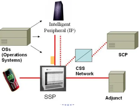
can be deployed throughout the network. This enables an operator to develop and deploy value-added services more efficiently. New capabilities can be rapidly introduced into the network. Once introduced, services are easily customized to meet individual subscriber’s needs. There are several main components in the IN architecture (Figure 2-2).
Figure 2-2: Architecture of the GSM Intelligent Network system 1. A service switching point (SSP) is an IN–capable switching system. 2. A service control point (SCP) provides the service control logics.
3. An intelligent peripheral (IP) provides resources like customized and concatenated
voice announcements, voice recognition, and dual-tone multi frequencies (DTMF) digit collection.
2.2.2 IN based GSM service with CAMEL
enhanced IN feature in GSM networks that enables users to carry personal services with them when roaming into other networks that support CAMEL.
2.2.3 CAMEL T-CSI trigger and MT user status
CAMEL operation requires additional CSI (CAMEL Subscription Information) to be included as part of a mobile subscriber's subscription information in the HLR. This CSI will be forwarded to the appropriate VLR when the mobile attaches and moves around the network. There are two types of CSI in the original CAMEL specfications; they are O-CSI (Originating - CAMEL Subscription Information) and T-CSI (Terminating - CAMEL Subscription Information). The contents of the CSI include gsmSCF Address, Service Key,
Default Call Handling, and TDP (Trigger Detection Point) List. The gsmSCF Address
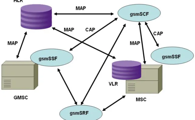
indicates the identity of the CSE (CAMEL Service Environment) to be used for service interaction, The Service Key indicates the OSS of the subscriber and is used to identify the service logic of the gsmSCF. It is administered by the HPLMN and is passed transparently by the VPLMN / IPLMN to the gsmSCF. The Default Call Handling indicates whether the call shall be released or continued when there is an error in the dialogue between the gsmSSF and gsmSCF. The TDP (Trigger Detection Point) List indicates at which detection point CAMEL triggering will take place. Figure 2-3 shows the main components
They are gsmSCF (GSM Service Control Function), gsmSSF(GSM Service Switching Function) and gsmSRF (GSM Specialized Resource Function). Between gsmSSF and HLR, they use MAP (Mobile Application Part) protocol. Between gsmSCF and gsmSSF, they use CAP (CAMEL Application Part) protocol.
Figure 2-3 CAMEL Architecture (Phase 2) Terminologies:
BCSM: Basic Call State Model CAP: CAMEL Application Part CSE: CAMEL Service Environment DP: Detection Points
GMSC: Gateway Mobile Switching Center IPLMN: Interrogating PLMN gsmSCF: GSM Service Control Function MAP: Mobile Application Part gsmSSF: GSM Service Switching Function HLR: Home Location Register gsmSRF: GSM Specialised Resource Function MSC: Mobile Switching Center PIC: Points in Call VLR: Visitor Location Register
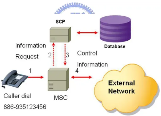
Figure 2-4 depicts a simple scenario of a voice call being made. When a subscriber starts to make a call, this request is received by the network's Mobile Switching Centre
(MSC). Assuming a detection point specified in the O-CSI is triggered, the MSC then sends a message that 'queries' the SCP. Note that the essential element of any CAMEL solution is a Service Control Point (SCP). This unit effectively hosts a database which holds the instructions needed for an intelligent application.
The SCP processes that query, comes up with an appropriate response and then sends a message back to the MSC telling what action it should take with the subscriber request for a specific service. The call is then connected in the most appropriate manner, a process which is transparent to the customer.
Figure 2-4 IN CAMEL procedure
Units (VRUs).
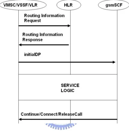
2.2.4 An example of signaling procedures using CAMEL
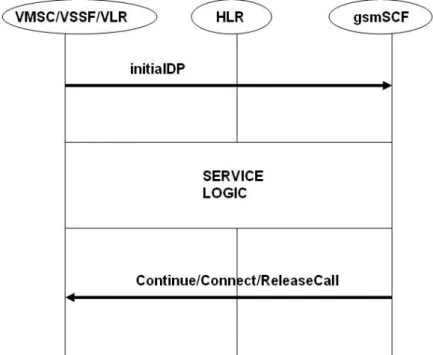
For a mobile originating call. if an active originating CAMEL Subscription
Information (CSI) is found in the VLR during the call set up of a MS (Mobile Station), the Visited Service Switching Function (VSSF) sends an InitialDetectionPoint message to the gsmSCF and the VMSC suspends the call processing. The InitialDetectionPoint shall
Figure 2-5 Mobile Originating Calls
always contain the service key, called and calling party number, calling party category, location number, bearer capability, event type Basic Call State Model (BCSM), location information and the International Mobile Station Identity (IMSI). After receiving the
message, the gsmSCF initiates the service logic processing CAMEL specific handling, as shown in Figure 2-5. For a mobile terminating call, the Gateway MSC (GMSC) in the interrogating PLMN identifies the HLR of the called party with the help of the MSISDN.
Figure 2-6 Mobile Terminating Calls
Then the GMSC sends a RoutingInformation-Request to the HLR. The HLR checks the CSI of the called party and sends the information stored in the subscriber record back to the GMSC. Now, the GMSC acts according to CSI. If the terminating CSI is active and the trigger criteria of a Detection Point (DP) is fulfilled, the call processing is suspended. An InitialDP message, which shall always contain the service key, called party number, event type BCSM and the IMSI, is sent to the CSE and the service logic execution is started.
Figure 2-7: Do-Not-Disturb Service
Figure 2-7 displays a common traditional IN service: do-not-disturb service. This is a service in which the callee (B) has the screening service logic at the SCP. Whenever someone calls him, the service logic determines whether the call should be routed to the callee's cell phone or an announcement (callee is not available now) should be played. In this particular case, when the caller (A) calls the callee (0935-123456), the SCP tells the switching system to route the caller’s call to an announcement. The caller hears that the callee is not available now.
2.3 SIP
Session Initial Protocol (SIP) is an application-layer control protocol that can establish, modify and teardown multimedia sessions, such as Internet telephony calls. SIP can also be
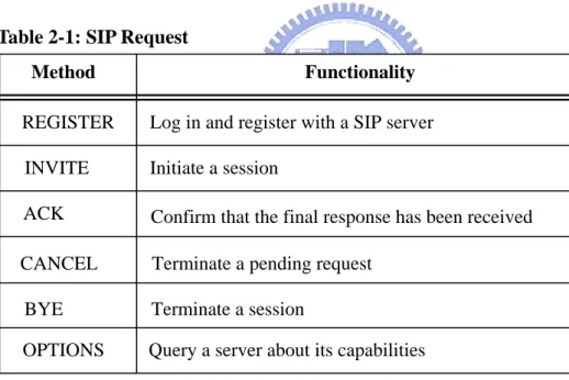
used to invite new participants to already existing sessions for multicast conferences. The Internet Engineering Task Force (IETF) SIP working group is responsible for SIP standardization. SIP can also be used in conjunction with several other IETF protocols, such as Session Description Protocol (SDP), to handle the setup, modification and teardown of multimedia sessions. SIP defines five types of network entities: (1) User Agent Client, (2) User Agent Server, (3) Registrar, (4) Redirect Server, and (5) Proxy Server. More detailed information can be found in RFC 3261 [16]. There are six methods and six classes of response, as listed in table 2-1 and table 2-2:
Table 2-1: SIP Request
Method Functionality REGISTER INVITE ACK BYE CANCEL OPTIONS
Log in and register with a SIP server Initiate a session
Confirm that the final response has been received Terminate a pending request
Terminate a session
Query a server about its capabilities
A SIP server can be stateless or stateful. The stateless implementation provides good scalability and the server need not remember anything about the call. SIP uses the format and syntax of HTTP. The SIP message is opaque (it can be any syntax); it can be described
Language (XML). SIP identifies a user with a Uniform Resource Identifier (URI), which can be placed in web pages, e-mail message or printed literature, to provide the user the ability to initiate and maintain a communication session.
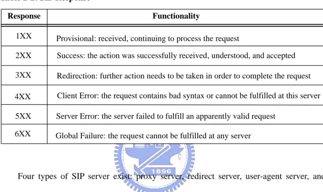
Table 2-2: SIP Response
Response Functionality 1XX 2XX 3XX 5XX 4XX 6XX
Provisional: received, continuing to process the request
Success: the action was successfully received, understood, and accepted Redirection: further action needs to be taken in order to complete the request Client Error: the request contains bad syntax or cannot be fulfilled at this server Server Error: the server failed to fulfill an apparently valid request
Global Failure: the request cannot be fulfilled at any server
Four types of SIP server exist: proxy server, redirect server, user-agent server, and registrar. A proxy server acts in a similar way to a proxy server used forwards for web access from a corporate local area network (LAN). Clients send requests to the proxy and the proxy either handles those requests itself or forwards them on to other servers, perhaps after performing some translation. A redirect server is a server that accepts SIP requests, maps the destination address to zero or more new addresses, and returns the new address to the originator of the request. Thereafter, the originator of the request can send requests directly to the address(es) returned by the redirect server. A redirect server does not inititate any SIP requests of its own. A user-agent server accepts SIP requests and contacts the user.
A response from the user to the user-agent server results in a SIP response on behalf of the user. A registrar is a server that accept SIP REGISTER requests. Typically, a registrar will be combined with a proxy or redirect server. SIP includes the concept of user registration, whereby a user indicates to the network that he or she is available at a particular address. The use of registration enables SIP to support personal mobility. Same as the GSM routing, we will introduce how SIP is routed in the next section.
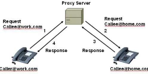
2.4 SIP routing
Two basic types of routing methods are exists. They are SIP Proxy Operation and SIP Redirect Operation. Figure 2-8 shows an example of the operation of a proxy server. If the message from the caller to Callee in is an invitation to participate in a call, the net effects is that the call is forwarded to Callee at home. Of course, it is necessary that the proxy be aware that Callee happens to be at home instead of at work.
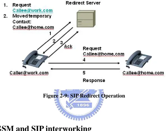
Figure 2-9 shows an example of the operation of the operation of the redirect server. The redirect server simply provides the information necessary to enable the originating client to correctly route the call, after which the redirect server is no longer involved.
Figure 2-9: SIP Redirect Operation
2.5 GSM and SIP interworking
For the SIP and GSM interworking, gateway (network gateway, NGW) will be required to provide the conversation from circuit-switched media to the packet and vise versa. Not only must there be media interworking, but there must also be signaling interworking. After all, SIP is a signaling protocol. If calls are to be established between a SIP-based network and the GSM network, then the SIP network must be able to communicate with the GSM according to the signaling protocol used in the GSM Network. In most cases, this protocol is SS7. For the establishment, maintenance, and teardown of
speech calls, the applicable SS7 protocol is the ISDN User Part (ISUP).
Figure 2-10: SIP to GSM Call
Figure 2-10 shows the scenario that call from SIP to GSM network. If SIP enables a SIP URI to have the form of a telephone number. The INVITE includes such a URI in the To: field, which is mapped to the calling party number of the initial address message (IAM). The from: field of the INVITE could also have a URI in the form of a telephone for the calling party. This would enable the called party to still avail itself of the GSM Caller-ID Service.
The GSM switch responds with an ACM, which is mapped to the SIP 183 (session progress) response. This response contains a session description and enables in-band information to be returned from the called switch to the SIP caller. Once the call is answered,
have an updated session description, since the session description in the 183 response is considered temporary and is part of an early dialog.
Figure 2-11: GSM to SIP Call
If the call from the PSTN to SIP (Figure 2-11), the 180 ringing response is used instead of the 183 session progress response, but this is for example purpose only. In this example, the 180 ringing is used by the NGW to trigger a ringing tone towards the calling party locally. Alternatively, the called SIP user agent might return a 183 (session progress) response, with an early media description (such as a ringing tone) to be played to the caller.
Although these two interworking examples might seem quite straight forward, seamless interworking between two different protocols is not often quite that easy, because rarely does a one-to-one mapping messages and parameters take place between on protocol and the other.
2.6 ENUM
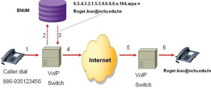
Electronic Number (ENUM) is a protocol defined in the IETF, RFC 2916 [17], for fetching Universal Resource Identifiers (URIs) given an E.164 number." More simply put, ENUM is a technology that enables a user to store contact information that can be accessed by another person through the use of one phone number. For instance, one could store a fax, voice, voicemail, e-mail, and home address all in a single ENUM Naming Authority Pointer (NAPTR). By using the ENUM, another person could access all the personal contact information contained within the NAPTR. Figure 2-12 shows a sample that describes ENUM mechanism use in Internet Telephony. The scenario is:
1. The caller dials the telephone number.
2. The caller’s VoIP service provider converts the telephone number into an ENUM domain name and launches a query to the ENUM.
3. The ENUM responds with the Internet address of the user. 4. The VoIP switch routes the call to the Internet.
5. The Internet routes the call to the VoIP service provider. 6. The VoIP service provider completes the call to the user.
ENUM is suitable for the PSTN / PLMN to static IP address’s SIP phone call (But not good for dynamic address SIP phone, like ADSL). While Caller dial an E.164 number
The SIP phone could be find in this mechanism.
Figure 2-12: ENUM Mechanism Used in Internet Telephony
2.7 Parallel ring service
We use the Parallel Ring Service Solution to provide one number service to GSM and IP network phone calls. So we simply describe the Parallel Ring Service here.
Parallel Ring Service is a mobile terminating (MT) service allows you to specify a second phone number to ‘Also ring’ – you can then choose which phone you answer the call on. For example, you could set the phone to also call your mobile so that if you are out of the office or not at home you won’t miss the call.
We can implement such service by several solutions, conventional, we have the Pure IN solution and Service node solution.
2.7.1 IN parallel ring service
If Parallel Ring is implemented by pure IN architecture, the SSP should have the version SR10 (GSM MSC Specification) functionalities, the most important is the Call Party Handling function. With this function, the IN (SCP) could use the ‘connect’ command to ‘grow’ several legs to the call terminating callees. So, in Parallel Ring’s case, if we want to page 2 phones parallelly, the Call Party Handling (CPH) Function should handles 3 legs concurrently. If more phones would be paged, the CPH function will be very complex, because all of the different situations of each call legs should be considered.
IN (gsmSCF) SSP (GMSC) SR10 (CS2 CPH) HLR T-CSI MSC SINAP7a MAP Subscriber MS #1: 0935000001 MSC ISUP Interrogating T-CSI initialDP: MT Call triggering Connect#1 #2:
Call party handling (CPH)
Subscriber DB Service Logic ISUP MAP3 AnyTimeInterrogating MS(s) #1, #2 MAP_SendRoutingInfo. MS(s) #1: 0935000001, #2: 0935000002 IAM IAM ABC: Message ABC : Protocol Subscriber MS #2: 0935000002 MT incoming line #1: 0935000001
Figure 2-13 shows how it works:
1. Caller dial Parallel Ring Service subscriber phone number. SSP interrogate this mobile terminated call to HLR.
2. HLR T-CSI shows the subscriber has an IN service, and then the call is triggered to the IN.
3. IN query database for the phones have to be paged and then ‘connect’ these phone numbers
Usually, the SR-10 version SSP is very expensive. Not for the special purpose, the operators will save the cost and just use the lower version SSP. That’s why some other solution, like service node and IN–service node integrated solution are introduced.
2.7.2 Parallel ring service using service node
In Service Node Solution, the Service Node implement the Call Party Handling (CPH) function. All of the call termination legs trunks are reserved. So, the trunk resources are wasted while any callee’s phone not online. (IN solution can solve this problem, because when IN interrogate the HLR, HLR returns mobile phone is offline, and then IN won’t paging this phone.)
Figure 2-14 shows that the procedure of the service node based Parallel Ring Service. 1. Caller dials Parallel Ring Service subscriber phone number. SSP interrogate this
mobile terminated call to HLR.
2. HLR informs the SSP route the call to a Service Node for a next stop.
3. Service Node query database for the phones have to be paged and then ‘connect’ these phone numbers.
Chapter 3 An IN and Service Node Integrated Parallel
Ring Service to Mobile Phones and IP Phones System
Design
Since IP phones have become more popular in recent years, one number parallel ring service to mobile phones and IP phones is attractive to mobile subscribers. In this chapter, we will describe an IN-based One Number Parallel Ring Service to GSM and IP Phones. Including system architecture, components functionality, and how it works.
3.1 Parallel Ring Service to GSM and IP Phone
In Parallel Ring Service, if we want to extend the mobile termination calls to both GSM mobile station and SIP phone, we should add the network gateway (NGW) in the middle of the GSM SSP (GMSC) and Internet. So according to the 2.7.1 and 2.7.2, we have the pure IN solution (Figure 3-1) and Service Node solution (Figure 3-2).
IN Parallel Ring Service to GSM and IP Phone(Figure 3-1):
1. A caller initiate a call and the call is routed to the gateway SSP of the called party. The SSP interrogate the HLR about this mobile terminated call. The HLR return the T_CSI of the called party to the SSP.
2. The T-CSI indicates the calle party subscribes an IN service, and then the SSP queries the gsmSCP, as indicated in the T-CSI, for instructins to handle the call. 3. The gsmSCP queries the subscriber database for callee’s service logic, if both of
call to callee’s mobile phone and SIP network gateway (NGW) and connect to callee’s SIP phone parallelly
IN (gsmSCF) SSP (GMSC) SR10 (CS2 CPH) HLR T-CSI MSC SINAP7a MAP MSC Interrogating T-CSI initialDP: MT Call triggering Connect#1 #2:
Call party handling (CPH)
Subscriber DB Service Logic ISUP MAP3 AnyTimeInterrogating MS(s) #1, #2 MAP_SendRoutingInfo. MS(s) #1: 0935000001, #2: 0935000002 IAM ABC: Message ABC : Protocol Subscriber MS #1: 0935000001 MT incoming line #1: 0935000001 ISUP IAM ISUP/SIP Gateway (NGW) SIP Subscriber MS #2: 0935000002 INVITE
Figure 3-1: IN Parallel Ring Service to GSM and IP Phone Service Node Parallel Ring Service to GSM and IP Phone(Figure 3-2):
1. A caller initiate a call and the call is routed to the gateway SSP of the called party. The SSP interrogate the HLR about this mobile terminated call. The HLR inform MSC the call should be routed to Service Node.
2. The Service Node queries the subscriber database for callee’s service logic,
3. If both of callee’s mobile and SIP phones are online, then Service Node forks the call into two branches: one to the called party’s mobile phone and the other to a SIP phone. Once any one of the phones is answered, the Service node connect the call and start the call session.
SSP HLR MSC MSC ISUP Service Node
Call Party Handling (CPH) Logic Subscriber DB MS(s) #1: 0935000001, #2: 0935000002 Subscriber MS #1: 0935000001 IAM MAP_SendRoutingInfo. IAM MT incoming line #1: 0935000001 ISUP IAM ISUP/SIP Gateway (NGW) SIP Subscriber MS #2: 0935000002 INVITE
Figure 3-2: Service Node Parallel Ring Service to GSM and IP Phone
3.2 IN and service node integrated solution
To provide parallel ring service without the support of the Call Party Handling (CPH) function in GSM SR-10 (GSM Specification) MSC, we can use an integrated IN and Service Node solution to save the circuit resource in GSM network.
Since the SSP does not provide the CPH function, we can implement the CPH function in a Service Node to provide Parallel Ring Service. Figure 3-3 depicts the atchitecture of this solution:
of replacing the MSC:
(1) GSM SR-10 is a very expensive MSC. Instead of upgrading the MSC, it is much cheaper to use an integrated IN and Service Node solution to provide the Call Party Handling Function.
(2) Trunk use can be saved with IN feature (Service Node will reserve the trunk once the paging activity started). Since trunk resource is also expensive in GSM network.
IN (gsmSCF) SSP SR8 (NO CPH) HLR T-CSI MSC SINAP7a MAP
Subscriber‘s SIP Phone ISUP
Interrogating T-CSI
Subscriber DB Service Logic
Subscriber’s Mobile Phone
SIP MSC SIP Location DB Multi-Protocol Service Node E 1 C P U 3 S I P S S 7 D S P SN AP server SCP AP server Multi-Protocols CPH Logic ISUP AnyTimeInterrogating MSISDN initialDP: MT Call triggering
ConnectSN /w MSISDN & SIP-URI IAM IAM IAM Invite Register / Update SIP MT incoming line 0935000001 MS: 0935000001 SIP: [email protected] MAP_SendRoutingInfo. MS: 0935000001 SIP: [email protected]
Figure 3-3 IN and Service Node Integrated Solution
1. A caller initiate a call and the call is routed to the gateway SSP of the called party. The SSP interrogate the HLR about this mobile terminated call. The HLR return the T_CSI of the called party to the SSP.
callee’s mobile and SIP phones are online, and then instructs the SSP to connect the call to a Service Node
4. The Service Node forks the call into two branches: one to the called party’s mobile phone and the other to a SIP phone. Once any one of the phones is answered, the Service node connect the call and start the call session.
3.3 SIP URI bearer in SS7 network design
Now we will start the description of the solution detail. We will discuss How to carry the SIP URI in the SS7 (GSM / PSTN core network) first.
SS7 Q.763 (ISUP) [11] is the recommendation which defined by ITU-T (International Telecommunication Union - Telecommunication Standardization Sector). It defines the protocol used to set-up, manage, and release trunk circuits in GSM network. In order to carry the IP phone status and information (eg. SIP URI) in SS7 network, extending the Q.763 ISUP parameter would be a doable method. This section will describe how to extend the parameters in Q.763 and how to carry it among the SS7 network nodes with intelligent network technology.
3.3.1 Q.763 (ISUP) parameters overview
ITU-T Q.763 Recommendation [11] specifies the formats and codes of the ISDN user part messages and parameters required to support basic bearer services and supplementary services.
The ISDN User Part (ISUP), a key protocol in the SS7 signalling system, defines the protocol and procedures used to set-up, manage, and release trunk circuits that carry voice and data calls over the GSM network between different switches. ISUP is used for both ISDN and non-ISDN calls. Table 3-1 shows the Q.763 Protocol Structure. (The ANSI and ITU-T have slightly different ISUP message format. Table 3-1 shows the ITU-T ISUP message format)
Table 3-1 ITU-T Q.763 ISUP (ISDN User Part)
Routing label (5bytes) Circuit identification code (2 bytes)
Message type code (1 byte)
Parameters varies according to message type values
Four parts of the signal just follow tha ASN.1 format, these four parts are: (1) Routing
label - The routing label is used by the relevant user part to identify particulars to which the
message refers. It is also used by the Message Transfer Part (MTP) to route the message towards its destination point. (2) Circuit identification code - The allocation of circuit identification codes to individual circuits is determined by bilateral agreement and/or in accordance with applicable predetermined rules. (3) Message type code - The message type code uniquely defines the function and format of each ISDN User Part message. Each message consists of a number of parameters. The message type code consists of a one-octet
function and format of each ISDN user part message. (4) Parameters – the parameters shows the parameters each message carried. It varies according to message type values. We will extend this part for carry more information of SIP phone. Detail will describe in following section.
Table 3-2: Q.763 Message type code
Message type Code
Address complete 0 0 0 0 0 1 1 0 Answer 0 0 0 0 1 0 0 1 Blocking 0 0 0 1 0 0 1 1 … … User-to-user information 0 0 1 0 1 1 0 1 … … Reserved for future extension 1 0 0 0 0 0 0 0
The message type code (table 3-2) consists of a one-octet field and is mandatory for all messages. The message type code uniquely defines the function and format of each ISDN user part message. Take “Answer” for example, it means the callee answer the call. In ISUP, we often call it ANM message.
Each ISUP message may carry several parameters, these parameters are defined at this document and looks like Table 3-3. Take user to user information parameter for example, we may use it for transfering application data between SS7 components.
Table 3-3: ISUP Q.763 parameters
Parameter name Code
Access delivery information 0 0 1 0 1 1 1 0 Access transport 0 0 0 0 0 0 1 1 Automatic congestion level 0 0 1 0 0 1 1 1 Backward call indicators 0 0 0 1 0 0 0 1
… … User-to-user information 0 0 1 0 0 0 0 0
… … Reserved for future extension 1 0 0 0 0 0 0 0
3.3.2 SS7 Q.763 parameter extend for the SIP URI
If we want to carry the SIP URI information in Q.763, the best method is insert it into the parameters. So we will describe the parameters and how to extend it to carry the SIP URI.
Each parameter has a name which is coded as a single octet. The length of a parameter may be fixed or variable, and a length indicator for each parameter may be included.
Table 3-4/Q.763 parameters
Parameter name Code
Access delivery information 0 0 1 0 1 1 1 0
Access transport 0 0 0 0 0 0 1 1
Table 3-4/Q.763 parameters
Parameter name Code
Backward GVNS 0 1 0 0 1 1 0 1
Call diversion information 0 0 1 1 0 1 1 0 Call diversion treatment indicators 0 1 1 0 1 1 1 0 Call history information 0 0 1 0 1 1 0 1 Call offering treatment indicators 0 1 1 1 0 0 0 0 Call reference (national use) 0 0 0 0 0 0 0 1
… …
Generic number 1 1 0 0 0 0 0 0
… … Original called number 0 0 1 0 1 0 0 0
… …
Redirecting number 0 0 0 0 1 0 1 1
… … User-to-user information 0 0 1 0 0 0 0 0
… … SIP-URI (Reserved for future extension) 1 0 0 0 0 0 0 0
Code 3-1 Signalling Interface Unit (SIU) connect message parameters
/* Argument used by Connect operation */ typedef struct { INAPAPI_DTYPE_InvokeID invokeID; INAPAPI_DTYPE_DestinationRoutingAddress destinationRoutingAddress; INAPAPI_DTYPE_AlertingPattern alertingPattern; INAPAPI_DTYPE_CorrelationID correlationID; INAPAPI_DTYPE_CutAndPaste cutAndPaste; INAPAPI_DTYPE_ISDNAccessRelatedInformation iSDNAccessRelatedInformation; INAPAPI_DTYPE_OriginalCalledPartyID originalCalledPartyID; INAPAPI_DTYPE_RouteList routeList; INAPAPI_DTYPE_ScfID scfID;
INAPAPI_DTYPE_Extensions extensions; INAPAPI_DTYPE_Carrier carrier; INAPAPI_DTYPE_ServiceInteractionIndicators serviceInteractionIndicators; INAPAPI_DTYPE_CallingPartyNumber callingPartyNumber; INAPAPI_DTYPE_CallingPartysCategory callingPartysCategory; INAPAPI_DTYPE_RedirectingPartyID redirectingPartyID; INAPAPI_DTYPE_RedirectionInformation redirectionInformation; INAPAPI_DTYPE_DisplayInformation displayInformation; INAPAPI_DTYPE_ForwardCallIndicators forwardCallIndicators; INAPAPI_DTYPE_GenericNumbers genericNumbers; INAPAPI_DTYPE_ServiceInteractionIndicatorsTwo serviceInteractionIndicatorsTwo; INAPAPI_DTYPE_INServiceCompatibilityResponse iNServiceCompatibilityResponse; INAPAPI_DTYPE_ForwardGVNS forwardGVNS; INAPAPI_DTYPE_BackwardGVNS backwardGVNS; INAPAPI_DTYPE_CallSegmentID callSegmentID; INAPAPI_DTYPE_LegID legToBeCreated; INAPAPI_DTYPE_LocationNumber locationNumber; INAPAPI_DTYPE_BearerCapability bearerCapability; INAPAPI_DTYPE_SuppressionOfAnnouncement suppressionOfAnnouncement; INAPAPI_DTYPE_OCSIApplicable oCSIApplicable; INAPAPI_DTYPE_ForwardingCondition forwardingCondition; INAPAPI_DTYPE_Ellipsis ellipsis; } INAPAPI_ARG_Connect;
See the table 3-4 design, extending the parameter (use the reserved row) for containing the SIP URI information. Thus the SIP URI could be delivered in SS7 network. In Code 3-1, the Signaling Interface Unit (SIU) C/C++ program header extraction shows the SCP connect information parameters. The existence SS7 network could only send these parameters from SCP to the service node or trunk gateway. According to the experience
in Code 3-1 could be successfully pass the test (These messages could be carried from SCP to service node in SS7 networ. So, for the real implementation in this time, we use these parameters instead the use of New Added SIP-URI parameter.
3.3.3 Deliver the Q.763 extension parameter in the GSM
network
IN (gsmSCF) SSP SR8 (NO CPH) SINAP7a Service Logic SIP Location DBMulti-Protocol Service Node E 1 C P U 3 S I P S S 7 D S P SN AP server SCP AP server Multi-Protocols CPH Logic ISUP Connect IAM SIP: [email protected]
Transmit SIP Address carried by extended SS7 Q.763 Parameters
SINAP7a CONNECT (message)
SIP-URI CALLER CALLEE Redirect# 0935000001@ 172.30.9.15 0922-440530 0935-999999 0935-555888
SS7 ISUP IAM (message)
SIP-URI CALLER CALLEE Redirect# 0935000001@ 172.30.9.15 0922-440530 0935-999999 0935-555888
Figure 3-4 SCP send the ISUP parameters to SSP with INAP CONNECT
After we can extend the Q.763 parameters, now SCP (IN) can use the CONNECT command to transfer the SS7 and SIP information.
service node. Fot the requirement of this thesis, it may carry the calling party number, called party number, and SIP_URI parameters.
3.4 SIP location database in SS7 network
If we want to integrate the SIP network into the traditional PLMN network, there should be a database that contains the SIP phones’ status and related information. Therefore, a well designed database is required.
3.4.1 SIP location and status database designed for SCP
Figure 3-5 SIP location and status database
We need a database that maintain the SIP phone location and Status in IN and Service Node integrated architecture. Here it is. This database integrates the SIP registratar and
like online, offline…etc. Also, this database maintains the URI of each SIP phone. And, the most important is that it will return the URI to SCP while the SCP query this database by MSISDN (E.164) number. This is just like the ENUM project works.
But, it not total the same as ENUM. ENUM is a DNS based database. But for the requirement of this integrated dual network system, we have to consider how to improve the performance issue (DNS is an hierarchical database, query may be an overhead), and have to do some change of the design. Thus the query will be faster.
3.4.2 Database requirement and schema
At first, we will describe the database schema requirement.In order to satisfy the requirement of the input (E.164 number) and output (SIP URI) and also have to meet the need of the SIP registratar, at least following field should be included in this database.
(1) MSISDN VARCHAR2 (28) (2) SIP_URI VARCHAR2(56)
/* use two SS7 Q.763 parameters to carry */ (3) SIP_ ID VARCHAR2(50)
(4) SIP_ STATUS INTEGER (5) PORT_NUMBER INTEGER
Second, we will describe the database speed up method. That is, using (1) the Linux system IPC (InterProcess Communication) tool – share memory technology, and (2) MSISDN 2 segment index. Because the E.164 MSISDN GSM cell phone number in
Taiwan’s National Format could be often write in 10 digits (the number distributed from telecom communication government department follow this rule), like 0935123456. So, for the local design, this number been segmented by the front 4 digits and other 6 digit, like 0935-123456. (Government agency often distributed the number to operator by front 4 digits, like 0935, for Taiwan Cellular Corporation). With the Linux system, we may use the share memory to implement such database and indexed by front 4 digits and then can reduce the full scan search time and update time. Like the following example:
0922 - 123456 123457 123458 234567 … 0935 - 123456 123457 123458 234567 …
After the row id of the database retrieved, then the other fields could be know almost at the same time. So, this design can speed up the query speed and quickly return the information to SCP. Since the architecture is centralized mechanism, the performance of the database query is an important issue have to be solved.
3.4.3 SIP register and update
Following we will describe how the SIP phone register and up date this database. The user agent (SIP phone) must register with a registrar. The registrar is a special SIP entity that receives registrations from users, extracts information about their current location (IP address, port and username in this case) and stores the information into location database. Purpose of the location database is to map sip:[email protected] to something like sip: [email protected]:5060. The location database is then used by called party's proxy server. When the proxy receives an invitation for sip:[email protected] it will search the location database. It finds sip:[email protected]:5060 and will send the invitation there. A registrar is very often a logical entity only. Because of their tight coupling with proxies registrars, are usually co-located with proxy servers.
Figure 3-6 shows a typical SIP registration. A REGISTER message containing Address of Record sip:[email protected] and contact address sip:[email protected]:5060 where 140.113.1.1 is IP address and 5060 is IP port of the phone, is sent to the registrar. The registrar extracts this information and stores it into the location database. If everything went well then the registrar sends a 200 OK response to the phone and the process of registration is finished.
Each registration has a limited lifespan. Expires header field or expires parameter of Contact header field determines for how long is the registration valid. The user agent must refresh the registration within the lifespan otherwise it will expire and the user will become unavailable.
3.4.4 Mapping the MSISDN and SIP URI
Now we may extend the SIP registratar with the MSISDN and then the database mechanism would be completed. To simplify the practice, we may use the
[email protected] for sample. This means the SIP ID would be the MSISDN. When SIP phone registry, separate the ID before the ‘@’, indexed and then can finished the
database insert. After this, mapping interface for the query will be the last job in this design. And then, others can query the MSISDN and SIP URI mapping information.
3.5 Use SCP in the GSM and IP networks
The brain of the value-added service in traditional PLMN is Service Control Part (SCP). If we want to integrate the SIP Phone controlling mechanism into the traditional PLMN, first, we should consider the SCP’s information. In this thesis, we add the SIP location database for the SCP, therefore, SCP could also know the status and related information of the SIP Phone.
The parallel ring service can be implemented with intelligent network technology. Using the parallel ring system, users could use the GSM mobile phones and SIP phones at the same time with same identifier (MSISDN). It won’t change the user behaviour a lot, and believed could be accepted by the subscribers in very short time.
In traditional PLMN Intelligent Network, Service Control Point (SCP) could get the GSM cell phone status (online, offline, call forward…) after interrogate the Home Location Register (HLR). Combine the SIP location database which is the Internet Telephone User Status Register Database, the different networks subscriber’s status could be both known at SCP, and then SCP could decide the paging behavior (Mobile Termination). This is shown in Figure 3-7:
IN (gsmSCF) HLR T-CSI Subscriber Profile Service Logic SCP AP server AnyTimeInterrogating MSISDN SIP Location DB 1. ConnectSN /w MSISDN & SIP-URI
SSP SR8 (NO CPH) MSC MSC Multi-Protocol Service Node 2.ConnectMSISDN 3. ConnectSN /w SIP-URI
ATI return values:
SIP Location DB/ Registar return values: (1) Idle (2) Not Reachable (3) Assumed Idle (1) Busy (2) Not Reachable (3) Assumed Idle (4) Not Provided From VLR
MS Live (3)||(4) SIP Live (1)||(3)
IVR(Interactive voice response)
4. Connectto Announcement MS Live (3)||(4) SIP Dead (2) MS Dead(1)||(2) SIP Live (1)||(3) MS Dead(1)||(2) SIP Dead(2)
1
2
3
4
LIVE LIVE DEAD DEAD initialDP: MT Call triggeringVMS (Voice Mail Server)
Figure 3-7 SCP Query both network’s Databases and then can do the paging strategy
First step scp query the SIP location database with key: MSISDN (0935-123456), and then step 2, the database return the SIP URI. And this time SCP finish the information gathering process (both MT GSM phone and SIP phone status).
Figure 3-8 shows how SCP play it role in this architecture. With this design, SCP could know both the GSM ad VoIP phones status at same time.
3.6 Service logic design
In this section, we will describe how to map the SS7 network and SIP network service logic and protocols, and will gives some examples for finite state machine design
3.6.1 ISUP and SIP protocols mapping
Figure 3-9 and figure 3-10 show the simple mapping signaling messages between SIP and ISUP. Detail will describe below:
Figure 3-9 shows the SIP initiate call to PSTN side. In this case, When SIP-INVITE send to the SIP-PSTN gateway, gateway will map the INVITE to IAM and send to PSTN network. When ACM comeback from PSTN side, gateway map ACM to SIP-183 (session progress) session description, and then SIP could hear the ringback tone from PSTN side (one-way audio). After gateway receive ANM, and then gateway send the 200 OK to SIP phone and start 2-way conversation.
Figure 3-9 SIP initiate the call to PSTN
Figure 3-10 shows that PSTN initiate call to SIP phone. When ISUP – IAM send to the gateway, and then gateway send the SIP – INVITE to SIP phone. SIP phone send 180 ring to gateway and translate as ringback to PSTN. At this case, gateway should generate the ringback tone to PSTN side. After the SIP phone return 200 OK to the gateway, and then gateway issue the ANM to PSTN. The conversation starts.
Figure 3-10 PSTN initiate the call to SIP
3.6.2 Scenarios examples
With the service node in PLMN, we can design the trunking gateway service logic and do the parallel ring service. The signaling is base on the mapping between 2 side networks. It not a easy program because the exception cases are too much and there’s 3 legs have to control. Take ISUP call to ISUP and SIP for example, there’s a MO - ISUP leg and MT – one ISUP leg and another SIP leg. This callcontrol logic should handle all of these legs and each leg has its own protocol. Every protocol’s signaling come from each leg should be a
handling function waiting there. And then do the right mapping according to the service logic scenarios. Following 2 cases introduce the example of the 3 legs call control. Let’s see how it works. For the carrier grade service, at least more than 10 scenario should be considered, here we show 2 of them:
Case 1: MO GSM - MT GSM offline, IP online, GSM pickup
Figure 3-11 shows the scenario that A call to B, B’s GSM Cell Phone Off-line but SIP Phone On-line situation. It’s an simple scenario because that B’s GSM cell phone reject the call.
Figure 3-11 A call to B, B’s GSM Cell Phone Off-line but SIP Phone On-line
Case 2: MO GSM – MT GSM online, IP online, IP Phone answer, GSM release
Figure 3-12 shows the scenario: A call to B, B’s GSM Cell Phone On-line and SIP Phone also On-line, at last B’s SIP-Phone pickup, system Release GSM Cell Phone. This
the GSM mobile phone.
There exist more scenarios like GSM phone online, SIP phone online, GSM phone answered, SIP phone released…and so on…too much scenarios and exceprions, expecially when there have to consider the condition of the call forward and call waiting.
Chapter 4 Implementation
This is the implementation part of this thesis using the IN and service node integrated architectrure. I practice the parallel ring service and design 5 Call Scenarios. Following sections are the architecture and explanation.
Most of them are satisfied the basic rule: When SCP Query SIP location Database, SCP could know IP Phone’s status and after Mobile terminating procedure, SCP also know the GSM mobile handset status. Then, SCP could do the right decision to see if redirect the call to the voice mail, announcement, just paging SIP phone, just paging the GSM cell phone, or do the parallel ring.
4.1 System setup
We implement this solution in SIEMENS GSM network (Version SR-8). SCP is a Signaling Interface Unit of INTEL. And Service Node and Trunk gateway is EXCEL Swich of the EXCEL Switching Corporation. Both SCP and EXCEL Switch are programmable. We use the IPCs (Operating System is Linux) of Advantech Company to host the application. SIP phone and stack are provided by Taiwan ITRI (Industrial Technology Research Institute) CCL(Computer and Communication Laboratory).
4.2 Scenarios
4.2.1 Scenario 1: mobile phone and IP phone are online
The scenario is (Figure 4-1):
(1) Caller dial callee’s MSISDN. After enter the mobile terminating process - query HLR, T_CSI (Termination CAMEL Service Info) trigger are detected, according to the Service Key and Global Titletranslation Trigger is executed, and waiting for SCP’s command.
(2) SCP query SIP location Database, get the SIP Phone’s status and SIP URI, and use the MAP_AnuTimeInterrogation (ATI) to query the status of the mobile station.
(3) SCP insert the SIP information in ISUP Q.763 new extended field (SIP_URI) and SS7 carry the parameter to the termination service node (trunking gateway)
(4) Paging the phones (GSM handset and SIP phone) at the same time (parallel). In Programmable Anymedia Switch do the design of Service Logic Call Party Handling Finite State Machine. For example, if SIP Phone Pickup, tear down GSM Phone circuit, connect SIP Phone.
SIP Location DB Multi-Protocol Service Node E 1 C P U 3 S I P S S 7 D S P H 3 2 3 SN AP server B is 0935-000001 Desk IP Phone WIFI Phone Soft Phone MSC GMSC IN (gsmSCF) SCP AP server HLR MT incoming line 0935000001 Internet Telephony PLMN ATI (Live) SIP DB Query Register / Update InitDP (trigger) Connect T-CSI Query IAM IAM IAM Invite