國立交通大學
材料科學與工程學系
博士論文
應用於 OLED 封裝之紫外光硬化環氧樹脂膠材
之性質與改善研究
A Study and Property Modification of UV-curable
Epoxide Resins Applied to OLED Packaging
學生姓名:江姿萱(Tzu-Hsuan Chiang)
指導教授:謝宗雍
博士(Dr. Tsung-Eong Hsieh)
應用於 OLED 封裝之紫外光硬化環氧樹脂膠材之性質與改善研究
學生姓名:江姿萱 指導教授:謝宗雍 博士 國立交通大學 材料科學與工程學系摘 要
本論文研究應用在有機發光二極體元件(OLEDs)封裝用之紫外光硬化樹脂 的特性和改質方法。OLEDs 需要氣密性優良的封裝結構以防止發光層及高活性 的陽極金屬因水氣入侵而劣化,良好的黏著性質為達成此一目標的必要性質之 一;本研究因此探討紫外光硬化環氧樹脂之組成對黏著以及各種相關物理性質之 影響,進而提出改善黏著等性質的方法。 本論文的主要研究項目包含:(i)單體種類對於樹脂黏著強度的影響;(ii) 偶合劑對於樹脂黏著強度的影響;(iii)三級胺對樹脂之紫外光/熱硬化、黏著強 度及黃化的影響;(iv)含 hBN(六方氮化硼)無機填充材之環氧樹脂做為覆晶 IC 封裝之填充底膠之研究。第一部分研究聚醇類、乙烯酯類和壓克力酸類單體, 對於樹脂縮收率、紫外光轉化率及玻璃接著強度的影響,實驗結果顯示聚醇類單 體效果最佳,其在進行陽離子光聚合反應時,擁有最小的縮收率(1.72%)、最慢 的光聚合轉化率(0.09 sec−1)和最大的黏著強度(153.35 kg/cm2)。第二部分研 究填加不同種類之偶合劑的樹脂在 ITO 玻璃上之黏著強度的影響,偶合劑種類 包含乙烯類、胺類、環氧類,乙基類及壓克力酸類;實驗結果顯示乙烯類偶合劑 可以促進自由基聚合,當其添加量在1.0 wt.%時,樹脂在 ITO 玻璃及玻璃基板有 最大的接著強度,其值分別為91.42 kg/cm2及153.35 kg/cm2。第三部分研究添加 不同種類三級胺的紫外光硬化樹脂之特性,其種類包含咪唑、1,2-二甲基咪唑、 2,4,6-三(二甲基胺-甲基)酚、1-甲基咪唑和 2-甲基咪唑;實驗結果顯示 2,4,6-三(二 甲基胺-甲基)可提高樹脂的玻璃轉化溫度(Tg = 72.3°C)、降低熱膨脹係數(CTE= 70.8 ppm/°C),在玻璃(> 199 kg/cm2 ),ITO 玻璃(> 182 kg/cm2)、PET(約 115 kg/cm2)和不銹鋼(約232 kg/cm2 )等基板上亦有最大的黏著強度,此外,2,4,6-三(二甲基胺-甲基)酚亦有最高的紫外光反應性和最佳的黃化改善效果(黃化指數 = 11.27;顏色參數 = 6.48)。 前述之研究成果亦被應用於 IC 之填充底膠製備研究,其利用六方氮化硼 (hBN)做為無機物填充物,添加量為 9.2 至 25.7 vol.%,並對電氣性質、熱性 質、硬化動力學、接著強度及黏度進行探討。與商用含二氧化矽之底膠比較發現, 當hBN 添充量在 15 vol.%以上時,擁有較高的 Tg與較低的CTE 值;當 hBN 添 充量在25.7 vol.%時則有最大的熱傳導係數(= 1.08 W/m°K);hBN 添加量愈高對 於基材的黏著強度愈低,對於不同的基材之黏著強度大小依序為氧化鋁 > 矽晶 片 > 錫鉛基板。
A Study and Property Modification of UV-curable Epoxide Resins
Applied to OLED Packaging
Student: Tzu-Hsuan Chiang Advisor: Dr. Tsung-Eong Hsieh Department of Materials Science and Engineering
National Chiao Tung University
Abstract
This thesis studies the properties and modifications of UV-curable epoxide resins applied to the packaging of organic light-emitting devices (OLEDs). A hermetic packaging structure is essential to OLEDs since the light-emitting layer and highly active cathode electrode inside the devices are rather vulnerable to moisture attack. Since good adhesion is one of the key properties for sealing resins to achieve such a purpose, a thorough study on the UV-curable epoxide resins was hence carried out so that an in-depth understanding on the effects of resin constitution on adhesion and methods of property improvements could be obtained. The main topics included in this works are: (i) the effects of monomer types on adhesion strength of resins; (ii) the effects of organo-functional silanes on adhesion strength of resins; (iii) the effects of tertiary amines on UV/thermal curing, adhesion strength and etiolation of resins; (iv) epoxide resins containing hBN (hexagonal boron nitride) as inorganic filler for underfill of flip-chip interconnection.
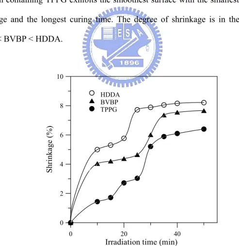
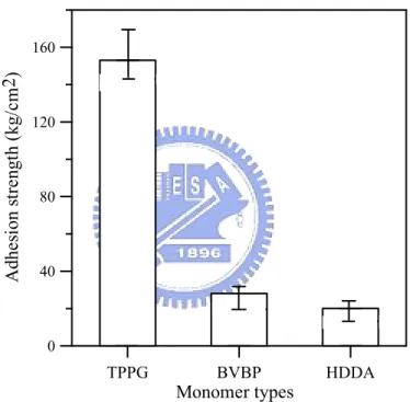
In part (i), epoxide resins containing polyol, vinyl ether and acrylate monomers were prepared and their effects on resin shrinkage, conversions and adhesion strength on glass substrate were investigated via a pull test. The polyol monomer was found to be the best since it provided the smallest shrinkage (1.72%) for cationic
photopolymerization, the slowest rates of polymerization at 0.09 sec−1 and the highest adhesion strength (153.35 kg/cm2). In part (ii), epoxide resins containing various organo-functional silanes including vinyl, epoxy, amino, methacrylic and acrylic groups were prepared and the adhesion strengths on indium tin oxide (ITO) substrate were studied. The vinyl silane was found to be able to promote the free-radical polymerization and the sample containing 1.0 wt.% of vinyl silane possessed the highest adhesion strength of 91.42 kg/cm2 on ITO glass and 153.35 kg/cm2 on glass substrate. In part (iii), various tertiary amines including imidazole, 1,2-dimethylimidazol, 2,4,6-tris(dimethylamino-methyl)phenol, 1-methylimidazole, and 2-methylimidazole were respectively added into the UV-curable epoxide resins. The addition of 2,4,6-tris(dimethylamino-methyl)phenol offered the highest glass transition temperature (Tg = 72.3°C), the lowest coefficient of thermal expansion
(CTE = 70.8 ppm/°C) and the highest adhesion strengths on glass (> 199 kg/cm2),
ITO (> 182 kg/cm2), PET (∼ 115 kg/cm2), and stainless steel (∼ 232 kg/cm2)
substrates. 2,4,6-tris(dimethylamino-methyl)phenol also exhibited the highest UV reactivity and the best efficiency on the etiolation improvement that the values of ∆YI and ∆E*ab as low as 11.27 and 6.48 were achieved in the UV-curable epoxide resins.
The knowledge acquired from the studies presented above was also applied to the preparation of underfill resin containing hBN filler for flip-chip interconnection. It was found that the hBN-resin possesses better dielectric properties in comparison with conventional underfill resins containing SiO2 filler. The hBN-resin also exhibited a
lower CTE and a higher Tg and, for the resin containing 25.7 vol.% hBN, it possessed
the largest thermal conductivity (1.08 W/m°K). The adhesion strengths of the composite resins decreased with the increase of hBN content and the adhesion strengths on various substrates was found to be in the order of alumina (Al2O3) > Si
誌 謝
首先要感謝我的父母親,因為他們的包容與支持,使我無顧之憂,得以完成 這最後一個階段的學業。 其次,我要感謝實驗室的學弟妹們,如羽筠、佳瑩和婉琪,與她們相處很愉 快,排解我在實驗時的低潮與苦悶;另外,我要感謝在實驗中協助過的朋友及學 長,如小余、明樺、沈明傑、王欽宏及陳建明學長等等;有這朋友及學長的幫忙, 才能使我的實驗能順利完成。 最後要感謝我的指導教授謝宗雍博士,平時對我的關心與鼓勵,讓我慢慢從 錯誤中成長,讓我學會獨立思考及獨立運作的能力;期望能以過去四年所學,在 未來翱翔出自己的一片天空。 最後在此再一次感謝大家,成就現在的我。Contents
Chinese Abstract ...i
Abstract ... iii
Acknowledgments...v
Contents ...vi
Figure Captions... viii
Table Captions ...xi
List of Symbols ...xii
Chapter 1 Introduction ...1
Chapter 2 Literature Review...5
2.1. Introduction of OLED Packaging ...5
2.2. Sealing Technologies of Electronic Devices...7
2.3. Requirements of Sealing Resins for OLED Packaging ...9
2.4. Comparisons of UV- and Thermal-curable Resins...10
2.5. Comparison of UV-Curable Epoxy and Acrylic adhesives ... 11
2.6. Commercial Sealing Resins for OLED Packaging ...15
2.7. Formulations of UV-curable Epoxide Resins ...16
2.7.1. Reaction Mechanisms of Photoinitiators ...16
2.7.2. Reaction Mechanisms of Monomers ...18
2.7.3. Effects of Silane Coupling Agents on Adhesion Strengths...26
2.7.4. Effects of Tertiary Amines on Etiolation ...27
2.8. Adhedion Strengths of Polymer Resins ...29
2.9. Underfill for Flip-chip IC Packaging...31
Chapter 3 Experimental Methods ...34
3.1. Experimental Methods of Sealing Resins for the OLED Packaging ...34
3.1.1. Materials ...34
3.1.2. Experimental flow...37
3.1.3. Characterization Methods ...38
3.2. Underfill Resins for Flip-chip Interconnections ...44
3.2.1. Materials ...44
3.2.2. Sample Preparation ...45
3.2.3. Dielectric Properties...46
3.2.4. Curing Kinetics of Resins ...46
3.2.7. Morphology...49
3.2.8. Adhesion Strengths ...49
3.2.9. Viscosity Measurement ...49
Chapter 4 Results and Discussion...50
4.1. Effects of Monomer Types on Adhesion Strengths of UV-Curable Resins..50
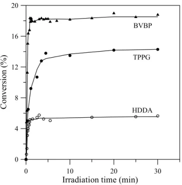
4.1.1. Kinetics of Photo-Polymerization of Resins...50
4.1.2. Effects of UV Curing Times on Shrinkages of Resins...52
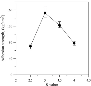
4.1.3. Effects of R Values...55
4.1.4. Effects of the Number of Hydroxyl Functional Groups ...57
4.1.5. The Effects of BPO and UV Reactivity ...59
4.2. Effets of Organo-Functional Silanes on Adhesion Strengths of UV-Curable Resins...62
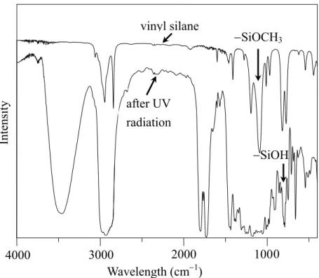
4.2.1. Chemical Reaction of Silane Containing Alkoxy Groups ...62
4.2.3. Effects of Silane Functional Groups on Adhesion Strengths...74
4.2.4. Effect of Weight Percentage of Vinyl Group Silane on Adhesion Strengths...75
4.3. Effets of Teritary Amines on UV-Curable Epoxide Resins...76
4.3.1. UV Conversions of Tertiary Amines...76
4.3.2. Tertiary Amines React with BPO under UV Irradiation ...77
4.3.3. Effect of Tertiary Amines on Thermal Conversions ...81
4.3.4. Effect of Tertiary Amines on Adhesion Strengths...85
4.3.5. Effects of BPO Contents on Amine-free Samples on Etiolation ...88
4.3.6. Effects of UV Irradiation Times on Etiolation...89
4.3.7. Effects of Post Curing Temperatures on Etiolation...91
4.3.8. Effects of Amine Types and Contents on Etiolation ...91
4.4. Study of Underfill Resins Containing hBN for Flip-chip Interconnection...94
4.4.1. Dielectric Properties...94
4.4.2. Curing Kinetics ...97
4.4.3. Effects on Coefficient of Thermal Expansion (CTE) ...100
4.4.4. Effects on Thermal Conductivity...101
4.4.5 Effects on Adhesion Strengths ...103
4.4.6. Viscosity of hBN-Resin ...105
Chapter 5 Conclusions ...106
Prospective Researches... 111
References... 116
Figure Captions
Figure 2-1. Schematic structure of the OLED device...6 Figure 2-2. Encapsulation methods for conventional bottom-emitting OLEDs ...7 Figure 2-3. Encapsulation methods utilizing transparent, multiple organic and
inorganic barrier coatings for FOLEDs. ...8 Figure 2-4. Monomer types can be utilized in photoinitiated cationic polymerization.
...19 Figure 3-1. Experimental flow...37 Figure 3-2. (a) The form and size of the truncated glass substrate and (b) the test
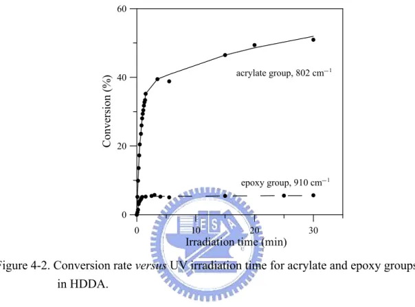
scheme of adhesion strength. ...43 Figure 3-3. Test assembly of thermal conductivity measurement...48 Figure 4-1. Conversion versus the time of UV irradiation for various monomers. ...51 Figure 4-2. Conversion rate versus UV irradiation time for acrylate and epoxy groups
in HDDA...52 Figure 4-3. Shrinkage change versus UV curing time of resin containing TPPG,
BVBP and HDDA monomers. ...53 Figure 4-4. Surface morphology of epoxide resins containing (a) TPPG (b) BVBP
and (c) HDDA after UV curing...54 Figure 4-5. Adhesion strength and scatter range for the various monomers. ...55 Figure 4-6. The R-value versus adhesion strength of resins containing polyol
monomer. ...57 Figure 4-7. Adhesion strength versus numbers of hydroxyl group of polyol
monomers...58 Figure 4-8. Surface morphology of epoxide resins containing (a) EOM (b) PCAT
after UV curing. ...59 Figure 4-9. 1H-NMR spectra of vinyl silane (a) before UV irradiation and (b) after
UV irradiation. ...60 Figure 4-10. Conversions of resin samples evaluated by absorbance change of peak
corresponding to (a) −SiCH=CH2 group located at 975.4 cm−1 and (b) epoxy
group at 910 cm−1 of FTIR spectra versus the UV irradiation times ...61 Figure 4-11. FTIR spectra of vinyl group silane and silane blended with
Figure 4-12. 13C-NMR spectra of (a) the alkoxy group of vinyl silane and (b) vinyl silane blended with photoinitiator after UV curing. 1H-NMR spectra of (c) the alkoxy group of vinyl silane and (d) vinyl silane blended with photoinitiator after UV curing. ...65 Figure 4-13. 13C-NMR spectra of (a) the epoxy silane and (b) epoxy silane blended
with photoinitiator after UV curing. 1H-NMR spectra of (c) the epoxy silane and (d) epoxy silane blended with photoinitiator after UV curing. ...67 Figure 4-14. 1H-NMR spectra of (a) vinyl silane and (b) vinyl silane blended with
photoinitiator after UV curing...69 Figure 4-15. 1H-NMR spectra of (a) acrylic silane and (b) acrylic silane blended with
photoinitiator after UV curing...70 Figure 4-16. 1H-NMR spectra of (a) methacrylic silane and (b) methacrylic silane
blended with photoinitiator after UV curing...71 Figure 4-17. 1H-NMR spectra for (a) amino silane and (b) amino silane blended with
photoinitiator after UV curing...72 Figure 4-18. OM images of epoxide resins containing: (a) vinyl, (b) epoxy, (c) amino,
(d) acrylic, (e) methacrylic slianes and (f) free of silane additive after UV curing ...73 Figure 4-19. Adhesion strength of epoxide resins containing various types of silanes
to ITO glass...75 Figure 4-20. Adhesion strengths of epoxide resins containing different weight
percentages of vinyl silane to ITO glass. ...76 Figure 4-21. UV conversion versus the irradiation time of resin samples containing
various amounts of 3-amine...77 Figure 4-22. 4-amine mixed with BPO before and after UV irradiation. ...79 Figure 4-23. H1-NMR spectra of 4-amine mixed with BPO (a) before UV irradiation
and (b) after irradiation. ...80 Figure 4-24. Structure of radicals generated by reactions of singlet oxygen with
(a)1-amine, (b) 2-amine, (c) 3-amine, (d) 4-amine and (e) 5-amine...80 Figure 4-25. 1-amine mixed with BPO before and after UV irradiation. ...81 Figure 4-26. Thermal conversion of resin samples containing various types of amines
subjected to post-curing at 80oC. ...84 Figure 4-27. (a) Adhesion strengths of resins containing 3-amine and 5-amines cured
various types of amines on (b) glass and (c) ITO substrates (d) shore D hardness of resins contained 1- to 4-amises. Adhesion strengths of resins contained various types of amines on (e) PET and (f) stainless steel substrates...87 Figure 4-28. The transmittance changes versus the BPO contents of resin samples. ..89 Figure 4-29. (a) ∆E*ab and (b) ∆YI values of resin samples containing various type of
tertiary amines subjected versus the UV irradiation time. ...91 Figure 4-30. (a) ∆E*ab and (b) ∆YI values of resin samples containing various type of
tertiary amines subjected versus the post-curing temperatures...92 Figure 4-31. Transmittance of resin sample containing various amounts of 3-aimine.
...93 Figure 4-32. Dielectric constants of hBN-resins as a function of test frequency. ...95 Figure 4-33. Dielectric constants of composite resins as a function of filler content
measured at 1 GHz...96 Figure 4-34. Tangent loss of composite resins as a function of filler content measured
at 1 GHz. ...97 Figure 4-35. Isothermal DSC thermograms of hBN-resins obtained at 150°C. ...98 Figure 4-36. Conversion of hBN-resins...99 Figure 4-37. Isothermal DSC thermograms of hBN and SiO2-resins containing 25.7
vol.% filler...100 Figure 4-38. CTE as a function of hBN and SiO2 content...101
Figure 4-39. Thermal conductivity of an EMC with various volume fractions of filler. ...102 Figure 4-40. SEM morphology of (a) hBN-resin and (b) SiO2-resin. ...102
Figure 4-41. Adhesion strengths of hBN- and SiO2-resins on various types of
substrates...104 Figure 4-42. Adhesion strengths as a function of filler content of hBN-resin on
Table Captions
Table 2-1. A comparison of thermal- and UV-curable resins... 11
Table 2-2. Comparison of free-radical and cationic polymerization resins. ...12
Table 2-3. Commerical Sealing Resins for OLED Packaging. ...15
Table 2-4. A summary of studies related to momomers for cationic polymerization. .20 Table 2-5. Dielectric properties of inorganic fillers...32
Table 3-1. The types and chemical structures of monomers...35
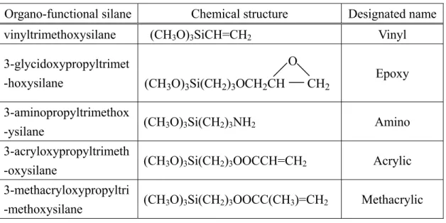
Table 3-2. Structures and designated names of organo-functional silanes. ...36
Table 3-3. Chemical structures and designated names of tertiary amines. ...36
Table 4-1. Number of hydroxyl group (–OH) of various poly monomers...58
Table 4-2. Curing times of samples containing various silanes...74
Table 4-3. CTE and Tg of resin samples containing various types of amines...84
Table 4-4. ∆L*, ∆a*, ∆b*, ∆E*ab and ∆YI of resin samples with different BPO content...89
Table 4-5. ∆L*, ∆a*, ∆b*, ∆E*ab and ∆YI of resin samples containing tertiary amines. ...93
Table 4-6. Tg of hBN-resins measured by DSC. ...99
List of Symbols
dbefore Density of sample before curing
dafter Density of a resin after curing
∆HT Total enthalpy change
CTE Coefficient of thermal expansion Tg Glass transition temperature
∆L* Degree of lightness
∆a* Coordinates designate the positions on red or green ∆b* Coordinates designate the positions on yellow or blue X, Y, Z Tristimulus values
Rp Polymerization rate
[Mo] Initial molar concentration of monomer before irradiation.
∆E*ab Color parameter
∆YI Yellowness index
ε Dielectric constants tanδ Tangent loss
κ Thermal conductivity
εc Dielectric constants of the composite ε1 Dielectric constants of filler
ε2 Dielectric constants of resin matrix
(tanδ)c Tangent loss of the composite
(tanδ)1 Tangent loss of the filler
(tanδ)2 Tangent loss of the resin matrix
Chapter 1
Introduction
Organic light-emitting device (OLED) become one of the promising flat panel displays (FPDs) technologies in the new millennium due to its excellent properties such as low power consumption, high efficiency, wide viewing angle, fast response time and compact and lightweight natures [1]. At present, bottleneck for the realization of OLEDs is the packaging technologies that must offer excellent hermetic sealing in order to prevent the moisture/oxygen attack on light-emitting materials and highly active cathode electode in the devices. Sealing of electronic devices can be accomplished by three ways: plastic, ceramics and metal. Conventinoal plastic packaging is impractical to OLEDs since it utilizes thermal molding to achieve the sealing. This is opposite to the fact that the light-emitting materials in OLEDs cannot tolerate high-temperature thermal processes [2], not even mention the high pressures involve during the hardening of sealing resins. Besides, plastic packaging is non-hermetic. Ceramic and metal packagings both provide good hermetic capability; unfortunately, they are not applicable to OLED packaging since their sealing processes often required high temperatures. Localized sealing methods such as welding could avoid overall heating of devices, however, it is unlikely to perform such a process on the ITO substrates of OLEDs due to the existence of anode electrode. In the sealing of conventional bottom-emitting OLEDs, first the UV-curable sealing resin is dispensed on the edge of ITO substrate that already contains sequent layers of light-emitting material and cathode electrode. A metal or glass lid is then pressured on the frame-like resin region and the whole structure is sent to the ovens for UV curing and post thermal baking to complete the sealing. The UV-curable resins
with good physical/chemical properties are thus specifically required for packaging of OLEDs. In addition, as the developing trend switches from bottom-emitting OLEDs to top-emitting OLEDs (TOLEDs) and flexible OLEDs (FOLEDs), encapsulation of devices is accomplished all over the light-emitting area so that transparency of resins becomes a further requirement for sealing resins [3-4].
The key components of UV-curable resins include oligomer, monomer and photoinitiator. According to either monomer type or photoinitiator type, the UV-curable resins can be classified into two main catalogies: free-radical photo-polymerization and cationic photo-polymerization. Most of the UV-curable resins are free-radical polymerization; however, they are not suitable for OLED packaging due to its inferior adhesion, low resistance to oxygen permeation and high etiolation under UV irradiation. As to the UV-curable epoxide resins via cation polymerization, their advantages include low shrinkage, good mechanical properties and high adhesion strengths on various substrates. Recently, many researches efforts have been poured on the developments of UV-curable epoxide resins specifically for OLED packaging [5]. The primary purpose of this work is hence to explore the UV-curable epoxide resins so that a collaboration development of sealing resins for OLEDs packaging can be accomplished. We respectively studied at the effects of monomer type, organo-functional silane types and tertiary amine types on the curing process, adhesion and related physical properties of the epoxide resins. The effects of tertiary amine types on the etiolation improvements of resins were also investigated in detail. With the knowledge obtained above, the resins with satisfactory properties were also adopted to prepare the underfill resin containing hBN inorganic filler for filp-chip interconnection.
of epoxide resins were investigated. It is found that the resin sample containing polyol monomer possesses the lowest polymerization reaction rate, the smallest shrinkage and the highest adhesion strength on glass substrate. Thus resin containg polyol monomer was also chosen as the base for subsequent studies related to organo-functional silane and tertiary amines.
In the part of study related to organo-functional silanes, vinyl, epoxy, amino, methacrylic and acrylic groups were chosen and the adhesion strengths of resins containing various silanes on ITO and glass substrates were studied. The vinyl silane was found to be able to promote the free-radical polymerization and the sample containing 1.0 wt.% of vinyl silane possessed the highest adhesion strengths of 91.42 kg/cm2 on ITO glass and 153.35 kg/cm2 on glass substrate.
Etiolation of UV-curable resin was resulted from the residual free radicals generated by photolysis of photoinitiator, polymer or photosensitizer. Though imidazole and other types of tertiary amines have been widely studied in the field related to thermal polymerization [6-9], their effects on the UV-curable epoxide resins and key physical properties are rarely reported. In this part of work, tertiary amines including imidazole, 1,2-dimethylimidazol, 2,4,6-tris(dimethylamino-methyl)phenol, 1-methylimidazole, and 2-methylimidazole were respectively added into the UV-curable epoxide resins and their effects on UV curing process, etiolation and adhesion were examined. The experimental results indicated that the addition of 2,4,6-tris(dimethylamino-methyl)phenol provided the best curing characteristics and physical property improvements of UV-curable epioxide resins. In addition to the best improvements of adhesion strengths on various substrates, such as glass, ITO, PET and stainless steel, appropriate amount (about 1.0 wt.%) of 2,4,6-tris(dimethylamino- methyl)phenol added in the reisns also offered the highest UV reactivity, highest Tg (=
∆E*ab as low as 11.27 and 6.48, respectively) of the UV-curable epoxide resins.
In the part of study related to underfill resin containing hBN filler, it was found that the addition of hBN is able to improve the dielectric properties of resin. It may also improve the physical properties such as CTE, Tg and thermal conductivity.
However, increase in hBN content might deteriorate the adhesion strength of the composite resins and the adhesion strengths of hBN resin on various substrates was found to be in the order of alumina (Al2O3) > Si > eutectic PbSn solder.
Chapter 2
Literature Review
2.1. Introduction of OLED Packaging
Figure 2-1 depicts the typical structure of OLEDs consisting of ITO glass substrate with anode electrode, hole-transport layer, hole-injection layer, light-emitting layer, electron transport layer, and cathode electrode [10]. The light-emitting layer inside can be either small-molecule or polymer based. The anode electrode is transparent conducting material with good hole injecting capability. It can be either ITO or a combination of ITO and poly(ethylenedioxy) thiophene (PEDOT). Insertion of hole transport material such as N,N′-diphenyl- N,N′-(3-methylphenyl)-[1,1′ biphenl]-4,4′-diamine (TPD) is for the enhancement of thermal stability and decrease of energy gap between hole transport layer and anode [11].
Various organic light-emitting materials have been developed for RGB color requirements. Tang and van Slyke adoped tris(8-hydroxyquinoline)aluminum (Alq3)
as light-emitting/electron transport layer, triaryl amine as hole transport layer to prepare the first thin-film type OLED [10]. Alq3 was subsequently utilized as the
singlet host material in the guest-host doped emitter systems, a key concept on the development of OLEDs, and incoperated with various dopants to emit desired lights. For instance, Alq3 can be doped with various coumarin compounds to emit orange,
green and blue lights, respectively [12]. Further, anthracene and its derivatives (ADN) have been widely used as the blue light-emitting materials [13]. The cathode electrode must possess good electron injecting properties and low work function. Presently, the available metals and alloys satisfied such requirements include Ca, Ag, Al, AlLi, Mg, MgAg, etc. However, they are highly active and may not be exposed in air ambient
during device operation. Besides, it is known that the light-emitting layers are vulnerable to the attack of moisture/oxygen [14]. A hermetic packaging structure is thus required for OLEDs.
Figure 2-1. Schematic structure of the OLED device [10].
There are many studies relating to the deterioration of OLEDs [15]. Most of them agreed that the dominant degradation mechanism in un-encapsulated OLEDs is the exposure of the organic-cathode interface to ambient moisture and oxygen. This leads to the oxidation and delamination of the active cathode as well as the chemical reactions of the light-emitting layers during device operation [16]. In order to inhibit the degradation, the packaging of OLEDs are commonly accomplished by first dispersing the UV-cured sealing adhesive around the active part of the device. After attaching a metal or glass lid on the frame-like resin region on ITO substrate, the UV curing is then carried to complete the sealing [17]. A schematic packaging structure of conventional bottom-emitting OLED is illustrated in Fig. 2-2. The sealing process must be carried out in an extremely dry ambient (< 1 ppm v/v; dew point = –76°C) [18] or at least in an atmospheres purged with dry nitrogen or argon. Desiccant such as calcium oxide (CaO) or barium oxide (BaO) is often spread on the device side of lid so as to getter the residual moisture/oxygen in the package or the undesired
Electron transport layer
Anode electorde Cathode electrode
Glass substrate
Hole injection layer Hole transport layer Light-emitting layer
V
substances diffusing through the sealing resin afterward [10]. Further, in order to terminate the photo-polymerization, increase the crosslinking density and eliminate residual stress of sealing resin, a post thermal curing at 80°C for 1 hr is usually performed.
Figure 2-2. Encapsulation methods for conventional bottom-emitting OLEDs.
Conventional lid-attachment packaging methods described above become inapplicable as the developments of OLEDs switching to TOLED and FOLEDs. The metal lid is incompatible with TOLEDs since it is not transparent; it may be replaced by glass lid or the devices may be encapsulated directly by resins with suitable transparancy. FOLEDs cannot be capped by metal or glass lid due to its rigidity. As shown in Fig. 2-3, encapsulation methods utilizing transparent, multiple organic and inorganic barrier coatings for FOLEDs has been demonstrated [19-20].
2.2. Sealing Technologies of Electronic Devices
The sealing technologies in electronic packaging can be classified into ceramic packaging, metal packaging and plastic packaging according to packaging structure and material usage. Ceramics/glasses and metals have relatively low moisture and gas permeability and hence ceramic packaging and metal packaging are known as the hermetic packaging. In these two types of packagings, hermetic sealing is achieved by
ITO substrate UV-curable sealing resin
Glass or metal lid
Desiccant OLED device layers
Figure 2-3. Encapsulation methods utilizing transparent, multiple organic and inorganic barrier coatings for FOLEDs [14].
one of the following methods: welding, brazing, soldering or glass frit sealing. However, these sealing methods all demand relatively high processing temperatures (e.g., commercial soldering process reaches as high as 350°C) that would definitely destroy the light-emitting material in OLEDs. Furhter, welding, brazing and soldering all require certain type of sealed interface metallization that is incompatible with the substrate fabrication of OLEDs. Brazing and soldering may also leave flux to reside in the packaging, which is harmful to the reliability. As a result, it may rule out the applications of ceramic packaging and metal packaging to OLEDs.
It seems plastic packaging is the only choice for OLED packaging. Plastic packaging indeed provides advantages such as thin outline appearance, ease of automation and low cost. However, it does not offer the hermetic sealing since the encapsulation resins are polymeric that do not resist well to moisture/gas permeation. Modification of resin structure to suppress its permeability is hence a must if plastic packaging were applied to OLEDs. Further, conventional plastic packaging employs thermal molding, radical spray or stencil printing to achieve the device sealing. They are impractical to OLED packaging since in these processes the polymeric resins are directly encapsulated on the device parts. In addition, these processes use
UV-curable epoxy
Barrier layers
Flexible polymer substrate Flexible polymer lid OLED device layers
thermosetting resins, i.e., the high temperatures and pressures involved in subsequent thermal curing of resins would definitely damage the light-emitting layer and active cathode electrode of OLEDs. In order to suppress the possible deteriorations caused by thermal effects, OLEDs hence requires UV-curable resins to achieve the sealing. The packaging structure commonly seen in conventional bottom-emitting OLEDs is illustrated in Fig. 2-2.
2.3. Requirements of Sealing Resins for OLED Packaging
For the sealing resins for OLED packaging, appropriate thermal properties compatible with those of substrate materials, high mechanical strengths, low outgassing, low oxygen permeability (< 10−5 cc/m2/day) and moisture permeability (< 10−6 g/m2/day) are generally require for satisfactory reliability [21]. In application points of view, low curing temperature, fast polymerization rate, high Tg, high
adhesion strengths on various substrates and appropriate flow properties are specifically demanded.
In addition to the diffusion through the resin matrix, moisture and oxygen atoms may also permeate into the device via the resin/substrate and/or resin/lid interfaces to induce the degardation. Hence, good adhesion properties of resin on substrate and anode electroden are required. Meanwhile, it may enhance the permeation and adhesion strength of resin by the addition of appropriate inorganic fillers [22]. Therefore, the choice of monomer is essential for the synthesis of resins for OLED packaging because the momoner type affects the reaction rate, shrinkage and adhesion strength of resin.
Outgassing of resins may result from the following sources: moisture in resin formulation, silane coupling agent, by-product of resin and cationic photoinitiator [23]. The outgassing phenomenon can be eliminated by: (i) curing at room-temperature and
reducing the curing time so as to avoid the evaporation of low molecular weight elements in coupling agent; (ii) utilizing the resin with solvent-free formula; (iii) utilizing the low volatility, high-purity elements for resin synthesis; (iv) increasing the crosslinking density of resin to suppress the permeation path of moisture and oxygen.
2.4. Comparisons of UV- and Thermal-curable Resins
During the past two decades, the science and materials related to photopolymerization have grown from esoteric researches into various industrial applications and become one of importance topics in polymer science and technologies. Inherency of these studies is the use of a specific photoactivator system that is able to absorb the incident UV and/or visible radiation and convert monomer or prepolymer into polymer or crosslinked network. In recent years, many studies related to the synthesis and photochemical properties of novel photoinitiators with more desirable properties haven been proposed [24-25]. The photoinitiators are virtually 100% “solids” and essentially there is no solvent or moisture entrapped in the adhesive stratum. Compare to traditional solvent-based or water-based thermal-curable resins, the UV-curable resins generally possess less shrinkage [26]. A comparison of thermal- and UV-curable resins is given in Table 2-1.
According to Table 2-1, though the thermal-curable resins exhibit higher Tg,
lower CTE and higher adhesion strengths than those of UV-curable resins, they do not fit to OLED applications due to higher curing temperatures, longer curing times and solvent-contained. As a result, how to improve the properties such as Tg, CTE and
adhesion strength of UV-curable resins becomes a challenge for their applications to OLED packaging.
Table 2-1. A comparison of thermal- and UV-curable resins.
Properties Thermal-curable resins UV curable resins
Propagation Thermal UV light
Curing temperature High Low (room temperature)
Curing time Long Short
Solvent Yes No
Shrinkage Large Small
Tg High Low
CTE Low High
Adhesion strength High Low
2.5. Comparison of UV-Curable Epoxy and Acrylic adhesives
UV-curable resins have been widely used in many applications such as coatings, encapsulation, inks, adhesives, and in the preparation of assembly substrates due to its fast curing and solvent-free features [27]. According to photoinitiator or monomer type in the resins, UV-curable resins can be classified into epoxy and acrylic resin systems that their photo-polymerization are via cationic polymerization and free-radical polymerization, respectively. Table 2-2 presents the comparison of chemical/physical properties, advantage and disadvantage of free-radical and cationic polymerization resins.
The mechanisms of free-radical polymerization include radical formation from initiator, initiation, propagation and termination [28]. As shown in Eq. (2-1), free radicals formed when the photoinitiator is irradiated by UV light. The free radicals then couple with monomers to initiate more free radicals as shown in Eq. (2-2). Initiation creates a free radical of polymer and a hydrogen atom with an unpaired electron. Propagation involves a variety of reactions (see Eq. (2-3)) and one of these is the reaction of free radical with an oxygen molecule to form a peroxy radical (Eq. (2-4)). The termination of photodegradation can be achieved by mopping up the free radicals to create inert products (Eq. (2-5)). This occurs naturally by the combination
of free radicals or can be assisted by using stabilizers in the polymer.
Table 2-2. Comparison of free-radical and cationic polymerization resins. Chemical/physical property Free-radical polymerization Cationic polymerization
Main component Acrylic Epoxy
Polymerization rate High Moderate
Initiation UV UV
Propagation UV UV and thermal
Post thermal curing No Yes
Oxygen resistance Poor Good
Moisture resistance Good Poor
Shrinkage Large Small
Adhesion strength Moderate High
Chemical resistance Moderate Good
Outgassing Poor Good
Advanteges
(1) Fully cured in seconds. (1) Excellent pot life; (2) Multi-performance
after cured (heat resistance/low shrinkage).
Disadvantages
(1) Poor oxygen inhibition; (2) Poor adhesion; (3) High shrinkage; (4) High outgassing. (1) Poor moisture resistance; (2) Photo-polymerization inhibited by alkali compound;
(3) Fully cured in mins.
Radical formation from photoinitiator: I⎯⎯→hν R• (2-1)
Initiation: R• +M→RM• (2-2) Propagation: • + • + → 1 RM M RM i (2-3) • • +O →ROO R 2 (2-4) Termination: RRM• +RM• →RM −M (2-5)
The mechanisms of cationic polymerization include photolysis, initiation, propagation and termination [29]. Photolysis occurs as the UV irradiation generates a number of reactive species (see Eqs. (2-6) and (2-7)) that subsequently react with the monomer to release the Brønsted acid (2-8). In the propagation step, ring-opening polymerization takes place by the attack of Brønsted acid to the epoxy groups and then repeating the addition of molecules of the monomer on to the oxiranium ion of polymer chain end as show in Eq. (2-9). Termination of the growing ionic chain can be caused by hydrogen-donating molecules as shown in Eq. (2-10). In cationic polymerization, termination process is relatively slow and is known to responsible to the dark cure phenomenon.
Photolysis: Ph3S+X− ⎯⎯→hν
[
Ph3S+X−]
∗ (2-6)[
Ph S+X−]
∗ +RH→Ph S+Ph• +R• +H+X− 2 3 (2-7) Initiation: H+X− +M→HM+X− (2-8) Propagation: H+X_ O R + O R H + X_ (2-9) Termination: O R H + + O R n O R n O+ R (2-10)The activation steps are similar in free-radical and cationic polymerization, however, initiation and propagation of free-radical polymerization are faster than those of cationic polymerization.
The UV-curable epoxy resins are the specifically applicable to OLED packaging due to their small shrinkage, excellent adhesion strengths and good resistance to chemical/oxygen permeation. Oligomers of UV-curable epoxy resins via cationic polymerization include glycidyl ether [30], cycloaliphatic epoxide [31] and oxetanes [32-33]. The cycloaliphatic epoxide containing epoxycyclohexane rings that possesss higher polymerization rate in comparison with other known epoxide monomers such as glycidyl ethers, glycidyl esters, and epoxides of α-olefins [34]. The ester and ether groups in glycidyl ethers are considerably less reactive than oxiranium cations in cycloaliphatic epoxide. The presence of ester and ether groups in monomers thus depresses their reactivity [35]. In addition, the ring strain of ethylene oxide (epoxy group) are known to be 114 kJ/mole while that for oxetane is 107 kJ/mol [36]. At the same time, the basicity (pKa) for above two ethers is 3.7 and 2.02 [37], respectively. Thus, with similar steric factors and ring strains in both cyclic ethers, the basicity of oxetane is considerably larger than that of ethylene oxide. Oxetanes is then more reactive than cycloaliphatic epoxides during the cationic photo-polymerization. The order of polymerization rate is oxetanes > cycloaliphatic epoxide > glycidyl ether, therefore adhesion strength of glycidyl ether will be the lowest when the three cyclic ethers are subjected to the same exposure time span of UV irradiation [34]. Further, adhesion strength of oxetanes is lower than that of cycloaliphatic epoxide due to its small mocular weight and fewer hydroxyl groups [38]. The cycloaliphatic epoxides thus become the most appropriate oligomer type for UV-curable epoxy resins applied to OLED packaging.Cycloaliphatic epoxides were hence adopted as the oligomer for
2.6. Commercial Sealing Resins for OLED Packaging
Most of the commercially available UV-curable resins for OLED packaging are of cation polymerization due to the advantages such as less outgassing during UV irradiation. Table 2-3 lists the products and properties of UV-curable resins for OLED packaging currently available in the market [39].
Table 2-3. Commerical Sealing Resins for OLED Packaging [39].
Company Nagase Chemtex Kyoritsu
Chemicals Taiyo Ink. Mitsui Chemicals. Products XNR5516HP XNR5516HV 8723K3 Phermetic Seal
PHS-100 Structbond
Main resin Epoxy Epoxy Epoxy Epoxy Epoxy
Exteriority Ivory Ivory Undertone-biscuit
and opaque -- Ivory
Viscosity -- -- 10 ∼ 100 Pas EHD-type, 2.5 rpm 150 Pas 25°C, E-type, 5 rpm 60 ~ 150 Pas EHD 3o Corn, 2.5 rpm
Tg 131°C (DMA) 134°C (DMA) 155±5°C (TMA) 80°C (TMA) 120±10°C (TMA)
CTE 37 ppm/°C 39 ppm/°C 88 ppm/°C --- 50±10 ppm/°C Shrinkage 4% 3% --- --- --- Moisture absorption 1.0 % 25°C, 168 hrs 1.0 % 25°C, 168 hrs --- --- 1.0 % 100°C, 30 min Adhesion strength 140± 50 kgf/cm2 Pull test 140± 50 kgf/cm2 Pull test --- 1 MPa Corning#1737 150±30 kgf/cm2
Glass cross peel
Mositure permeability 16 g/m2-day 60°C/90%RH, thickness: 100 µm 16 g/m2-day 60°C/90%RH, thickness: 100 µm 10.6 g/m2-day (85°C/85%RH) 4.9 g/m2-day; (65°C/95% RH) 20 g/m2-day 65°C/90%RH, thickness: 100 µm 8.5 g/m2-day 65°C/90%RH, thickness: 100 µm 70±10 g/m2-day 80°C/95%RH, thickness: 100 µm 9±2 g/m2-day 40°C/90%RH, thickness: 100 µm Cure conditions 6 J/cm2 + 80°C/1hr 6 J/cm2 + 80°C/1hr 6 J/cm2 + 100°C/10min or 80°C/30min 2 J/cm2 + 80°C/1hr 8 J/cm2
2.7. Formulations of UV-curable Epoxide Resins
There are three essential components of UV-curable epioxide resins: oligomer, photoinitiator and monomer. The maximum amount of oligomer is determined by its molecular weight that, in turn, is determined by the maximum viscosity that could be handled by the end user. In addition, a high molecular weight and low functionality ensure the small shrinkage and thereby the good adhesion strenghts. The photoinitiator and monomer determine the reactivity, viscosity, physical properties and reaction mechanism of resin during UV irradiation. Other additives such as silane coupling agent and tertiary amines are for the promotion of adhesion strength, acceleration of thermal crosslinking desity, and suppression of etiolation. In below, reaction mechanisms of the photoinitiator, monomer, silane coupling agent and tertiary amines in epoxide resins during UV irradiation are discussed.
2.7.1. Reaction Mechanisms of Photoinitiators
Photoinitiators available for cationic polymerization include aryladiazonium salts, diaryliodonium salts and triarylsulfonium salts, phenacylsulfonium, 4-hydroxyphenylsulfonium salts, sulfoxonium salts and mixed-ligand arene cyclopentadienyl metal salts [40]. The most widely used cationic photoinitiators are the onium salts, in particular the triarylsulfonium and diaryliodonium salts. Onium salts and mixed ligand arene cyclophentadienyl metal salts with complex metal halide anions are the commercially available photoinitiators for crosslinking the epoxy groups via cationic polymerization. The onium salts are thermally stable ionic compounds with good solubility properties in both organic solvents and water. The most important property of onium salts is their ability to decompose and efficiently generate acid upon UV irradiation. The rates of polymerization depend on the acids
− 6
AsF < − 6
SbF . In addition, the nucleophilicity of the counterions decreases as − 4 BF > − 6 PF > − 6 AsF > − 6
SbF . The tendency of the propagating chains was related to F− abstraction and hence the highest termination of cationic chain ends by −
6
SbF [41]. This study adopted triphenylsulfonium salts as the photoinitiator since they contain the anion with the faster polymerization rate, SbF6−. The photolysis of
triphenylsulfonium salts was first reported by Knapzyck and McEwen [42-43] and the reaction mechanism was studies by Crivello et al. in 1978 [44]. In particular, diaryliodonium salts and triarylsulfonium salts are also investigated as photoinitiator and thermal initiators of cationic polymerization [45]. Triarylsulfonium salts possess high thermally stability; they undergo rapid photolysis when irradiated by UV light of wavelengths ranging from 200 to 300 nm. Both homolytic and heterolytic cleavage mechanisms are involved in the photolysis of the triarylsulfonium salts photoinitiator. In the homolytic process, the excited state first cleaves to release diphenylsulfinyl radical cation, phenyl radical and anion. Equation (2-11) depicts the reactive species including aryl radicals, aryl cationic radicals, aryl cations and the Brønsted acid
( + −
6
SbF
H ) generated by the photolysis of the photoinitiator [44-46].
S S R UV R S S S S R 2 monomer SbF6 SbF6 + + + SbF6 H+ (2-11)
2.7.2. Reaction Mechanisms of Monomers
In UV-curable epoxide resins, monomers determine the properties of reacting systems and final cured products according to their chemical structures. As described previously, free-radical and cationic polymerizations can also be classifiec according monomer types. The components containing electron-rich centers, such as the double bonds in vinyl ethers and the oxirane groups in epoxy resins, are suitable for cationic polymerization. On the contrary, electron-deficient double bonds such as those in acrylates and maleate systems may be readily polymerized in the presence of free radicals induced by appropriate photoinitiators [47].
Cationic photopolymerization was first studied by Crivello, et al. [41] who adopted diaryliodonium salts to react with various monomers such as cyclic ethers, cyclic formals and acetals, lactones, vinyl monomers, sulfur containing monomers, organosilicone monomers and monomers containing the epoxide group. They also discussed the cationic polymerization of multifunctional vinyl ether monomers [48] and the reactivity of cycloaliphatic epoxide [31]. Furthermore, a series of cationic photopolymerizable epoxide monomers cantaining benzyl, ally, propargyl acetal and ether groups that can stabilize free radicals were synthesized [41]. These monomers may enhance the reactivity of cationic photopolymerization in the presence of onium salt photoinitiators [49].
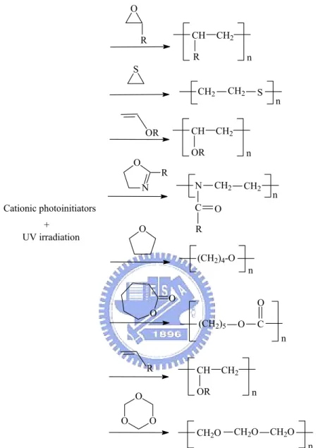
Figure 2-4 list the monomer types reported by Crivello [50] that can be utilized in cationic photo-polymerization and their nucleophilicities determines the rate of the attack by a cationogen and by the subsequent attack of additional monomer molecules on the growing cationic center. Among these, the most popular monomer is the epoxy group. Oxetanes monomer was also studied by Crivello et al. and it is the monomer type with the fastest polymerization rate [32,33,51]. In addition to epoxy monomer,
investigated in details and the related studies are summarized in Table 2-4. O R CH R CH2 n S CH2 CH2 S n OR CH OR CH2 n N O R CH2 n N CH2 C R O O (CH2)4-O n O O (CH2)5 O C O n R CH OR CH2 n O O O CH2O CH2O CH2O n Cationic photoinitiators + UV irradiation
Table 2-4. A summary of studies related to momomers for cationic polymerization.
Monomer References Triethyleneglycol divinyl ether Decker et al. (1996) [52]
Synthesis of Silicon-containing vinyl ether Itoh et al. (1997) [53]
Caprolactone polyols Wu et al. (1999) [54]
Poly(ε-caprolactone) polyols Yagci and Schnabel (1999)
[55]
Synthesis 1-butenyl and 1-pentenyl ethers Kaur et al. (1999) [56] Poly(tetrahydrofuran), poly(caprolactone triol) and
ethylene glycol
Tilbrook et al. (2000) [57] Diethylenglycol divinylether and isobutylvinylethr Toba, Y. (2000) [58] Aliphatic urethane divinylether, isophtalate divinylether
Aliphatic ester divinylether
Decker et al. (2001) [5] Cycloaliphatic epoxide resin, DGEBA and SU8 Boey et al. (2001) and
(2002) [59,60] Ethyleneglycol divinyl ether, di(ethyleneglycol) divinyl
eher, tri(ethyleneglycol) divinyl ether, butanediol vinyl ether, cyclyhexanedimethanol divinyl ether and glycidyl vinyl ether
Chappelow et al. (2002) [61]
Butyl vinyl ether and methyl methacrylate mixtures Braun et al. (2002) [62] Cyclic acetals (1,3-dioxolane, 1,3-dioxpane and
1,3,6-trioxocane)
Pantiru et al. (2002) [63]
1-propenyl-vinyl ether Sangermano, et al. (2002)
[64] Siloxane functionalized polyols, cycloaliphatic epoxide resin and ε-caprolactone derived polyols
Chen and Soucek (2003) [65-66]
5,5-dimethyl-1,3-dioxane-2-thione Yonet (2003) [67]
Epoxy-functional siloxane monomers and oligomers Jang and Crivello (2003) [68]
Oxetane Monomers, fluorinated oxetane monomer and silicon-containing oxetane monomers
Sangermano et al. (2004) [69,70]
Oxiranes and oxetanes Falk, et al. (2005) [51]
In this work, curing behaviors of resins containng various monomers such as polyol, vinyl ether and acrylate via cationic polymerization were investigated. The
described as follows:
(1) Reaction Mechanisms for Epoxide Resin:
Equations (2-12) and (2-13) depict the two processes involved in the initiation of photoinitated cationic polymerization. TheH+SbF6− is the strong Brønsted acid protonation which may induce the cationic polymerization of epoxide resin to produce oxiranium ion as presented in Eq. (2-12). The cationic polymerization then takes place by attacking protonated epoxide on another epoxide resin as shown in Eq. (2-13).
+ O C O O CH2 O O C O O CH2 O H H+SbF6 SbF6 + O C O O CH2 O H + O C O O CH2 O O C O O CH2 O O C O O CH2 OH + + SbF6
(2) Reaction Mechanisms for Polyol Monomer:
Cationic polymerization of the resin samples containing polyol monomer is the similarly depicted by Eqs. (2-11) and (2-13). The growing oxiranium ion chain, the product of Eq. (2-12), undergoes nucleophilic attack by the polyol to generate protonated ether as shown in Eq. (2-14). Penczek et al. [72] demonstrated that in the presence of polyols, the attack of the hydroxyl at the propagating oxonium ion chain end takes place more rapidly than usual ring opening mechanism. According to this, hydroxyl group of the polyol intercepts the oxonium ion terminus of the growing polyether chain. Deprotonation of hydroxyl groups of the polyol caused by the (2-13) (2-12)
epoxide monomer, the products of Eq. (2-14) [73], results in the termination of the growing polymer chain and transfers to the monomer to start new chains as shown in Eq. (2-15). Repetition of above process generates a hydroxyl end group for continuing the termination and transfer processes. This mechanism is expected to occur to some extent during cationic ring-opening polymerization initiated by Brønsted acids because terminal hydroxyl groups are always formed as end groups shown in Eq. (2-16). Therefore, the presence of polyols has considerable effect on the cationic ring-opening polymerization of UV-curable epoxide resins [74].
O C O O CH2 O H R'OH C O O CH2 O R' H HO O + + SbF6 SbF6 O C O CH2 O R' HO + O HSbF6 O C CH2 O R' HO O C O CH2 O O O O O O
(3) Reaction Mechanisms for Vinyl Ether Monomer:
Vinyl ether monomers possess a much more pronounced tendency toward cationic polymerization and do not undergo free-radical polymerization because they contain electron-rich centers, e.g., the highly nucleophilic double bonds caused by (2-14)
(2-15)
onium ions and alkoxyl groups [62,75]. Vinyl ether monomers, featured by a combination of π-donor (C=C) and n-donor (R−O+(R)2, onium ions), contain two nucleophilic sites [76]. The polymerization mechanisms for resin samples containing vinyl monomer are the same as shown in Eqs. (2-11) to (2-13). From Eq. (2-17), the formation of active species for the initiation of cationic polymerization takes place by the attack of nucleophilic on a vinyl ether group to generate the alkoxycarbenium ion. In Eqs. (2-12) and (2-17), only the attack by protons is shown because they are the most prominent species involved in the initiation. The rates of both reactions are expected to be fast. The carbocation, formed by the initial protonation of the vinyl ether groups, can induce polymerization of either other vinyl ether or an epoxide group as shown in Eqs. (2-18) and (2-19) [50,77]. Cationic polymerization of the protonated epoxide of Eq. (2-19) and oxiranium ion can take place by the nucleophilic attack of vinyl ether group as shown in Eq. (2-20). It results in the termination of the growing polymer chain and transfers to the monomer that thereafter can form start new chains shown in Eq. (2-21). The two possible reactions, the propagating oxiranium ions are converted into alkoxycarbenium ions and vice versa, are shown in Eqs. (2-19) and (2-20). Similar crossover reactions can be written for any reactive chain end generated during the course of the polymerization and the positions of these equilibriation are dependent on the relative stabilities of the two types of reactive species and the corresponding reactivities of the two monomers. Repetition of this process regenerates an ether end group that continues the termination and transfer processes. This mechanism is expected to occur to some extent during the cationic epoxide ring-opening polymerizations initiated by Brønsted acids because terminal alkoxyl groups always form as the end groups as shown in Eq. (2-22). Cationic polymerizations of vinyl ether adhesive resin system are shown in Eqs. (2-13) and
(2-20) either does not occur or takes place very slowly due to the relatively high stability of the oxiranium ion compared to that of carbocation.
+ H2C CH OR H3C CH OR + H+SbF6 SbF6 CH OR H3C + H2C CH OR CH OR H3C CH2 CH OR + + SbF6 SbF6 CH OR H3C + O O C CH2 O O C O O CH2 O CH OR H3C + + O SbF6 SbF6 O C O O CH2 O H C O O CH2 O HO H2C CH OR OR C H3C + + SbF6 SbF6 O C O CH2 O HO + CH OR H3C HSbF6 O C O CH2 HO O C O CH2 O O O O H2C O CH OR H2C CH+ OR (2-17) (2-18) (2-20) (2-21) (2-19) (2-22)
(4) Reaction Mechanisms for Acrylate Monomer:
Fast polymerization is particularly easy to obtain in the resin samples containing acrylate monomers due to the existence of electron-deficient double bonds. Acrylate is often with the structure of H2C=CHCOOR in which R is an arbitrary group that does
not significantly affect the mechanism of the polymerization. The phenyl free radicals produced by the photolysis of the cationic photoinitiator has sufficient energy to initiate the free-radical polymerization [78]. During cationic polymerization, photoinitiator and dicycloaliphatic epoxide may also react with acrylate monomer to undergo the free-radical polymerizations. The mechanisms are depicted in Eqs. (2-11) to (2-13) and Eqs. (2-23) to (2-25). The free-radical polymerization can be divided into three classes: the photochemical event leading to the first monomer radical, the propagation, and the termination process of the reaction as shown in Eqs. (2-23) to (2-25) [79]. Phenyl radical (see Eq. (2-11)) can react with acrylate monomer to induce grafting in accord with a homopolymerization reaction shown in Eq. (2-23). The addition of acrylate monomer to a macroradical results in a larger macroradical, as shown in Eq. (2-24) and termination occurs when the macroradicals are recombined as shown in Eq. (2-25). C OR' O CH2 + CH C OR' O CH CH2 C OR' O CH CH2 C OR' O CH2 CH + C OR' O CH CH2 C OR' O CH CH2 (2-24) (2-23)
C OR' O CH CH2 C OR' O CH CH2 C OR' O CH CH2 C OR' O CH CH2 + C OR' O CH CH2 C OR' O CH CH2 C OR' O CH CH2 C OR' O CH CH2
2.7.3. Effects of Silane Coupling Agents on Adhesion Strengths
Silane coupling agents are commonly adopted as the surface modification species and primarily serve as adhesion promoters in composite materials to achieve strong bonding of polymers on metals, glass, minerals etc. [80]. Silane coupling agent typically possesses alkoxy groups (OR) and an organo-functional group (R'). The alkoxy groups hydrolyze in the aqueous environment and form covalent bonds with hydroxyl groups on the surface as well as with other hydrolyzed silane molecules. The organo-functional group may also reacts with the matrix resin [81-82]. A properly chosen organo-functional group for a specific application increases the interfacial strength significantly. In some cases the adhesion enhancement is due to the formation of covalent linkages with the polymer via chemical interactions to produce so-called interpenetrating polymer network (IPN) [83]. The widespread usage of organic-functional silanes prompts an in-depth study of the mechanisms of adhesion reinforcement. In this study, the organo-functional group was chosen according to its reactivity and compatibility with the photoinitiator. Silane coupling agents with organo-functional groups of amine [84], epoxy [85], methacrylic [86], acrylic [87] and vinyl [88,89] are utilized for adhesion enhancement. Depending on the method of application, a silane coupling layer normally consists of several monolayers. There are basically four different methods of applying silane coupling agents: deposition (2-25)
from aqueous solutions, deposition from organic solutions, integral blend method and deposition as a primer [90]. Among these, deposition from organic solutions was used in this work.
2.7.4. Effects of Tertiary Amines on Etiolation
Transparancy becomes an important property of UV-curable resins for direct encapsulation of advanced OLEDs such as TOLEDs and FOLEDs. A common detriment to transparency of UV-curable resins is the etiolation phenomenon resulted from the poor resistance to subsequent UV irradiation. Etiolation of UV-curable resins is induced by: (i) residual photoinitiators that promote the photo-yellowing reactions [91-93]; (ii) hydrogen-atom was abstracted by the residual photoinitiator [94]; (iii) oxidization caused by the presence of functional groups containing residual free radicals in resins [95]; and (iv) hydroperoxidation resulted from the formation of conjugated unsaturated carbonyl products with strong UV absorption at the wavelength of 275 nm [96].
The etiolation of resin samples was resulted from the residual free radicals generated by photolysis of sulfonium slat photoinitiator, polymer or photosenizate. The radicals react with oxygen in air to produce free radicals via the oxidation reaction shown in Eq. (2-26) [97]. As depicted by Eqs. (2-27) and (2-28), the free radicals further react with polymer (RH) and other free or phenol radicals to form hydroperoxide (ROOH) and ester, respectively. It is known that the emergence of hydroperoxide induces the etiolation of resins [79,98-99]. The ROOH then decomposes into alkoxy and hydroxide radicals in accordance with Eq. (2-29) [100,101] and subsequently reacts with RH to form alkyl radical (Eqs. (2-30)). The alkyl radicals are continuously formed by the repetition of reactions shown in Eqs. (2-26) to (2-31). The more residual free radicals generated in the resin samples, the
more hydroperoxide were produced and the severer etiolation occurred in the UV-curable epoxide resins.
• • +O →ROO R 2 (2-26) • • +RH→ROOH+R ROO (2-27) ROOR R ROO• + • → (2-88) • • + →RO OH ROOH (2-29) • • +RH→ROH+R RO (2-30) O H R RH OH• + → • + 2 (2-31)
Etiolation suppression of UV-curable resins utilizing monoacrylate of a cyclic carbamate [102], monoacrylate of a cyclic urethane [102] and amine acrylate [96,103] have been reported. Etiolation of UV-curable resin improved by the addition of tertiary amines could be explained by the oxygen scavenging processes as depicted by Eqs. (2-32) to (2-34). During UV irradiation, singlet oxygen was produced by a triplet energy transfer from photosensitizer (i.e, the free radical initiators such as BPO) to ground-state oxygen [104].The singlet oxygen may react with tertiary amines via an electron transfer process to produce α-aminoalkyl radicals in accordance with Eq. (2-32) [105]. The α-aminoalkyl radicals depicted by then react with oxygen to produce α-hydroperoxyamine (HOOCH2NR2) and α-aminoalkyl radical via the
reactions shown by Eqs. (2-33) and (2-34) [46,101].
N CH3 R R + 1O 2 CH2 N R R + HO2 (2-32)
N CH2 R R + O2 CH2 N R R OO CH2 N R R H N CH2 R R OOH + CH2 N R R (2-34)
Tertiary amines are common thermal accelerators in epoxy resins to reduce curing temperatures and promote thermal conversions. One of the special features of tertiary amines is that they may react with carbonyl compounds, singlet oxygen and other species via an electron transfer process to improve the low ionization potential property [102].
2.8. Adhedion Strengths of Polymer Resins
Adhesion strength of polymer resins is resulted from the formation of chemical bonds between main chain of polymer resin and the substrate. Attraction resulted from van der Waals force of molecules in polymer resin and substrate is another source of adhesion [103]. In addition, crosslinking in resin inhibits the sliding between molecule chains so as to enhance the adhesion strength. However, the resin becomes stiff when crosslinking density is too high. The interfacial stress thus cannot be released and fracture may occur along the resin/substrate interface.
In order to enhance the adhesion strength, functional groups are commonly selected to promote interfacial chemical bonds or specific interactions that may produce hydrogen bonds. In general, chemical bonds is much more effective than hydrogen bonds in the adhesion enhancement. Some useful functional groups for adhesion enhancement are briefly described below [104].
(i) Carboxyl groups promote the adhesion on metals, glass, and polymers. They can be incorporated into resins by copolymerization with carboxyl monomers, or
using additives containing carboxyl groups.
(ii) Hydroxyl, methylol and nitrogen-containing groups promote the adhesion on various organic and inorganic substartes.
(iii) Epoxide groups promote adhesion on various organic and inorganic substrates containing active hydrogens such as hydroxyl, carboxyl, amino and amide groups.
(iv) Highly reactive isocyanate groups promote adhesion on substrate surfaces containing hydroxyl, carboxyl, amino or amide groups.
(v) Phosphoric acid group can be incorporated into a polymer by reacting phosphoric acid with a polymer containing an epoxide group. Such a functional group promotes adhesion on metal and ceramic substrates.
(vi) Sulfonic acid group can be incorporated into a polymer by copolymerizing with sulfoethyl methacrylate. Such copolymers improve adhesion on a variety of substrates.
Furthermore, several compounds are known to promote adhesion by chemical coupling between resin and substrates. These include silanes, esters of phosphoric, phosphonic, or phosphorous acid, chromium complexes and titanates.
There are a variety of adhesion test methods, e.g., single lap joint tests (thin susbtartes), thick substrate shear test, double lap joint tests, strap joint test, scarf joint of overlap test, shear joint tests, T-peel test, flexible-to-rigid peel test, pull-off, test butt joint tests and pull-out tests of tension pull tests [105]. These test methods in general determine the adhesion strength from the force required to pull a resin sample off the substarte surface (or a part from the substrate surface). In this work, pull-off test was adopted to evaluate the adhesion strengths of resin samples on various substares.
is also important when reporting the data of adhesion test. The locations of breakage/fracture can be classified as follows [106]:
(i) Substrate breaking: breakage occurs in substrate;
(ii) Cohesive breaking: breakage occurs in the resin matrix;
(iii) Interface breaking: breakage occurs along the resin/substrate interface; (iv) Mixture breaking: A combination of above types of breakages.
2.9. Underfill for Flip-chip IC Packaging
The pursuit of high speed and high performance of electronic products raises the size and device density of IC chips. Power consumption increases accordingly and, for the development of encapsulation resins for IC chips, the ability for the resins to satisfactorily dissipate heat is essential. Unederfill was originally served as sealant and mechanical support for flip-chip (FC) joints on IBM mainframe computer modules in 1964 [107]. The early work led to the discovery that thermo-mechanical fatigue could be reduced by filling resin in between the solder bump joints. The underfill technology hence becomes essential for the improvements of reliability, in particular to the assembly of flip-chip ICs on organic boards in which the CTE mismatches are sigificant. The underfill is a polymeric adhesive that serves to reduce the strain of the solder joints between the die and the substrate. Thus, the application of underfill would enhance the reliability performance of flip-chip on board assembly by at least one to two orders of magnitude over that of a nonunderfilled one.
Epoxide resin is one of the most popular organic materials for encapsulation due to its relatively low price, excellent processing ability, and low viscosity. Its deficiencies include low thermal conductivity and high CTE. According to their publications, it has been shown that in general the dielectric properties of polymers and blends are depended on their structure, crystallinity, morphology, and the
presence of inorganic fillers or other additives such as silica [108-110], silicone carbide (SiC) [111-112], alumina (Al2O3) [112-113], aluminum nitride (AlN) [114-116]
and boron nitride (BN) [117]. However, the dielectric constants of SiC, Al2O3, AlN,
etc. are relatively high as shown in Table 2-5, and are undesirable for electronic packaging that always requires low dielectric properties. At present, most of flip-chip interconnections are underfilled by silica-filled epoxy resins that have been used in IC industry for almost 30 years because of their good mechanical and electrical properties, low cost and much easier to process than inorganic encapsulants. The advantages provided by epoxy/silica composites have received a lot of attentions in electrical insulation applications such as outdoor high-voltage installations for the replacement of ceramic insulators [118].
Table 2-5. Dielectric properties of inorganic fillers.
Filler Dielectric constant (at 1 MHz) Tangent loss (×10−4, at 1 MHz)
SiC 40 ∼ 42 500 [119]
Al2O3 8.5 ∼ 8.9 2 ∼ 3 [119]
AlN 8.8 ∼ 8.9 1 ∼ 5 [119]
SiO2 4 2 [120]
hBN 3.9 < 2 [121]
The signal integrity, as it propagates through the package, is a direct function of the conductor’s resistivity, dielectric constant and the loss tangent. It is important to recognize that the dielectric constant and tangent loss can be strong functions of the frequency. In general, the dielectric tangent loss is not a strong function of frequency for ceramic packages, while the tangent loss is generally large and can have strong resonances at higher frequencies for plastic packages, especially above 1 GHz. In addition, underfill adhesion is crucial to the integrity and reliability of the assembly. It