1943-0655 (c) 2015 IEEE. Translations and content mining are permitted for academic research only. Personal use is also permitted, but republication/redistribution requires IEEE permission. See
Efficiency Enhancement of Organic Light-Emitting Diodes on
Flexible Substrate with Patterned Inverted Conical Structure
Yi-Jun Wang1, Jian-Gang Lu1, 2*, and Han-Ping D. Shieh1, 3, Fellow, IEEE1. National Engineering Lab for TFT-LCD Materials and Technologies, Department of Electronic Engineering, Shanghai Jiao Tong University, Shanghai, 200240, China
2. State Key Laboratory of Luminescent Materials and Devices, South China University of Technology, Guangzhou, 510641, China 3. Dept. of Photonics & Display Institute, National Chiao Tung University, Hsinchu, 300, Taiwan
Abstract: The total internal reflection (TIR) effect in conventional electroluminescent devices causes a large amount of light energy trapped in the devices and induces the heat energy that adversely affects the performance of the device. In order to enhance the light out-coupling efficiency without sacrificing the electrical properties, a patterned inverted conical (PIC) structure fabricated by focused femtosecond laser on flexible substrate was demonstrated. Compared with the conventional flexible OLED, the OLED with PIC structure exhibited the current efficiency increased by a factor of 2.6 without any emission spectrum altered. In addition, the flexible OLED with PIC substrate can avoid the mirror reflection effect under the strong ambient light for a better visual experience. This highly effective method is compatible with current device fabrication process and is applicable for full-color OLED display and lighting.
Index Terms: Micro-optical devices,Optoelectronics,Microstructure fabrication.
1. Introduction
A high optical device efficiency is still hindered by the total internal reflection (TIR) effect owing to the refractive index mismatch at the interface of various functional layers of electroluminescent devices to achieve higher brightness [1–3]. The external quantum efficiency (ηEQE) of an organic optoelectronic device is generally determined by ηEQE = χ•ηIQE, where χ is
the light coupling efficiency and ηIQE is the internal quantum efficiency related to the probability of electron-photon
conversion in the active region. Nowadays, the internal quantum efficiency of OLEDs has been dramatic improved to nearly 100% by using phosphorescent dopant materials [4]. Conversely, the light-extraction efficiency is still limited to 20%, which is far below the desired level [5]. Hence, a substantial increase in the external quantum efficiency is essential to enhance the light out-coupling efficiency of electroluminescent devices.
Several of techniques have been reported to enhance the light coupling efficiency from either the internal mechanism or the external construction on the back surface of substrate. For internal mechanism, embedded low-index grids were proposed by Y. Sun et al., which can increase the efficiency by a factor of 2.3 [6] and a maskless wet etching method was presented by J. H. Jang et al., which can improve the power efficiency by 54% [7]. For external construction, J. J. Shiang et al. illustrated volumetric scattering mechanisms, which can increase the OLED output by 40% [8] and S. Möller et al. utilized
poly-dimethyl-siloxane lenses to increase the OLED efficiency by a factor of 1.5 [9]. By modifying the directions of light propagating and adjusting the refractive index difference between the different functional layers, these approaches have shown the positive effect on the extraction of light out-coupling on glass substrate. However, flexible is one of the most important superiorities for OLEDs, which requires the flexible plastic substrate instead of solid glass substrate, yet the features of plastic (such as much thinner than glass, and non-high temperature resistance), limited parts of the methods to be applied for flexible OLEDs.
In this paper, we present a technique using patterned inverted conical (PIC) fabricated by a femtosecond laser to enhance the out-coupling efficiency of flexible OLEDs. The flexible green OLED with PIC structure exhibited a substantial enhancement in the optical out-coupling. As the flexible PIC- Polyethylene terephthalate (PET) can be directly used as a substrate, the proposed method is highly compatible with current fabrication processes of OLEDs.
2. Design Principle & Fabrication Process
2.1. Extraction Principle
Light trapping is a critical factor that limits the performance of electroluminescent devices. The light extraction from the organic emission layer in conventional OLEDs is suppressed owing to the waveguide in the multilayered sandwich structures and plasmonic quenching at the metallic cathode. The light-energy proportion in each mode can be approximately calculated by Snell’s law with optics modeling according to the refractive indices of the organic emitting layer (n ~ 1.71), PET substrate (n ~ 1.5), and external ambient condition (n ~ 1). Only 18.8% of light can be directly coupled out into the air, 31.3% of the light is trapped as substrate mode, and approximately 45.9% is dissipated in the ITO/organic layers as a waveguide mode, followed by the total internal reflection (TIR) limitation.
In conventional OLEDs, by using high refractive index material, ITO (n~1.9), as anode, a large proportion of lights (45.9%) were trapped in ITO/organic layers but not in substrate. In order to increasing the proportion of trapped lights in substrate, index matched material should be used as anode, according to the classical electromagnetic theory [11]. PEDOT: PSS (n~1.53) is a good candidate as its index is well matched with PET substrate (n~1.6). Combined PEDOT: PSS with PET substrate, the proportion of light trapping in PET substrate was increased from 31.3% to 54.8% with a factor of 1.75 [12]. The out-coupling efficiency can be increased by a factor of 3.9 in theoretically.
To extract energy from PET substrate, a patterned inverted conical (PIC) structure was produced, as shown in Fig. 1. In conventional flexible OLEDs, a part of light could be out-coupled (e.g. Ray A in Fig.1 (a)) and rest of them are trapped by the TIR which normally occurred on the interface of PET/air (e.g. Ray B in Fig.1 (a)). The PIC was able to alter the optical path of the light propagating in the substrate, break the TIR limitation via multiple refraction and increase the out-coupling efficiency, as schematically illustrated in Fig. 1(b) (e.g. Ray C).
Fig. 1. Schematic of the mechanism for the out-coupling efficiency enhancement: (a) conventional flexible OLED structure and (b) proposed method with PIC structure.
2.2. PIC Fabrication
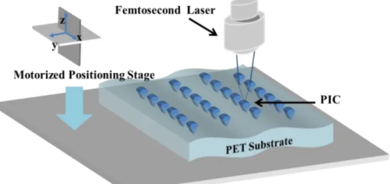
The PIC was fabricated by a femtosecond laser on a motorized x–y–z micro-positioning stage, as shown in Fig. 2. This stage has a 0.01-mm-step motor for precise positioning of the fabricated pattern as pre-design specifications. A laser beam propagated through the substrate in a perpendicular direction and converged on the PET substrate by a focal lens. The inverted conical structures were formed by melting the PET with laser radiation. In order to reveal the PIC structure clearly, the SEM images with top view and cross-sectional of PIC are illustrated in Figs. 3(a) and 3(b) respectively. The inverted conical is about 30 μm-diameter, several micrometers-depth and 150 μm-pitch. The density of PIC is approximately 16.7% (PIC density≈30/ (30+150)), as shown in Fig. 3(a).
1943-0655 (c) 2015 IEEE. Translations and content mining are permitted for academic research only. Personal use is also permitted, but republication/redistribution requires IEEE permission. See
3. Simulation Results & Analysis Discussion
In order to investigate the external coupling efficiency of the PIC structure, the 3D geometric model of the OLED was built by the ray tracing software, Light tools 7.2, which employs the Monte Carlo method [13].Three main parameters—arrangement of PIC, the refractive index of the anode, and the density of PIC—are account for the enhancement in the out-coupling efficiency. The factors related to the increase in the optical efficiency were simulated and are summarized in Tables 1–3 after normalization. A conventional device without PIC structure was also calculated as a reference. All the simulation results were only based on ray-optic modeling but excluding the surface plasmonic, interference and micro-cavity effect. Besides, in order to keep the simulation as close as possible to the experiment, the depth-to-width ratio of PIC was fixed as 2:1 when calculating the optical efficiency in the simulation.
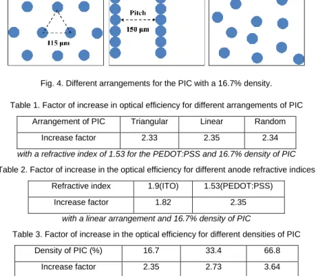
Fig. 4. Different arrangements for the PIC with a 16.7% density.
Table 1. Factor of increase in optical efficiency for different arrangements of PIC Arrangement of PIC Triangular Linear Random
Increase factor 2.33 2.35 2.34
with a refractive index of 1.53 for the PEDOT:PSS and 16.7% density of PIC
Table 2. Factor of increase in the optical efficiency for different anode refractive indices Refractive index 1.9(ITO) 1.53(PEDOT:PSS)
Increase factor 1.82 2.35
with a linear arrangement and 16.7% density of PIC
Table 3. Factor of increase in the optical efficiency for different densities of PIC Density of PIC (%) 16.7 33.4 66.8
Increase factor 2.35 2.73 3.64
with a linear arrangement of PIC and a refractive index of 1.53 for the PEDOT:PSS
The different arrangements with a density of approximately 16.7% for the PIC are shown in Fig. 4. In order to maintain a similar density, the lengths of the regular triangle and pitch of linear are set as 115 μm and 150 μm, respectively. As summarized in Table 1, PICs with different arrangements exhibit a similar increase in the optical efficiency by a factor of 2.33, 2.35, and 2.34, compared with the reference device. It implies that the optical efficiency can be enhanced effectively by the PIC, but it is insensitive to the specific arrangement.
As summarized in Table 2, more light was coupled to the substrate from the waveguide mode as the refractive index of the anode well matched with the substrate, leading to the optical efficiency greatly enhanced by factors ranging from 1.82 to 2.35 which implies that Combination of a matched-refractive-index anode with the PIC substrate can enhance the optical efficiency obviously.
As summarized in Table 3, the optical efficiencies were improved by factors of 2.35, 2.73, and 3.64 as the PIC density increased from 16.7% to 66.8%. A larger amount of emitted light can be effectively out-coupled by breaking the TIR limitation due to multiple refraction by increasing the density of the PIC. As the density of PIC reaches 66.8%, the factor of increase of 3.64 in the optical efficiency is very close to that of the maximum value in theory (3.9), implying that all of the light trapped in substrate is mostly out-coupled. The 66.8% density of the PIC is an optimal value for optical efficiency enhancement.
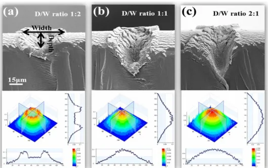
Fig. 5. The OLED light intensity distribution were modulated according to their different depth-to-width ratios (a) 1:2, (b) 1:1, and (c) 2:1 of PIC.
By controlling the laser radiation energy and repetition rate precisely, the inverted conical structures with different depth-to-width ratios such as 1:2, 1:1, and 2:1, can be formed, as shown in Figs. 5(a)-5(c). A low density of laser energy (100 nJ per pulse) with slow repetition rate (50 MHz) was used so that the energy can be absorbed by the material in large region to form a small depth-to-width ratio structure, as shown in Fig.5 (a). Conversely, a high density of laser energy (300nJ per pulse) with fast repetition rate (300 MHz) could be employed so that the energy can be focused on a very small region instantaneously to form large depth-to-width ratio, as illustrated in Fig.5(c). Three different kinds of depth-to-width ratios (1:2, 1:1, and 2:1) of PIC profiles were also simulated to prove their effects on modifying the light distribution. As shown in Fig. 5(a), the small depth-to-width radio (1:2) with large vertex angle of inverted conical induced lights to wide viewing angle and formed the symmetrical light intensity distribution with two peaks. The medium depth-to-width radio (1:1) induced part of lights to normal direction, as show in Fig. 5(b). With the increasing of depth-to-width radio (2:1) (e.g. Fig. 5(c)), the vertex angle of inverted conical became sharp and modified the light distribution similar to the Lambertian. It means that OLED light distributions can be modulated with different conical shapes to satisfy various needs.
4. Experimental Results & Discussion
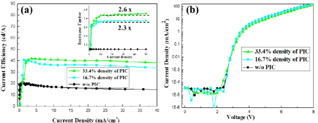
To verify the proposed method, green OLEDs on a 100 μm-thick PET substrate with PIC densities of 0%, 16.7%, and 33.4% were fabricated. The 2:1 depth-to-wide radio of PIC with rectangular arrangement was made to keep the same light distribution as conventional OLED. The current efficiency with its increase factor is shown in Fig. 6 (a). With the increasing of current density, the increase factors are gradually stabilized at 2.3 and 2.6 for densities of 16.6% and 33.4%, respectively, compared with the reference device. The electrical properties about the voltage versus the current density are plotted in Fig. 6(b). The improvement in the optoelectronic properties of the flexible OLED devices should be mostly attributed to the enhancement in the optical efficiency, as the green OLEDs on the PIC substrates have the similar current density compared with the reference device, as shown in Fig. 6(b). It indicates that the PICs simply increased the light output from the PET substrate but did not affect the electrical properties of the OLEDs. Moreover, when the density of PIC changed from 33.4% to 66.8%, the pitch of the PIC was decreased from 60 μm to 30 μm, the uneven distribution of the heat during the fabrication process caused by laser irradiation was aggravated by the decreased pitch, which results in PET substrate scrolling, thus, a PET substrate with a 66.8% density for the PIC was not yet successfully produced. This issue could be overcome by using discontinuous scanning mode to relax the heat energy focus on small region. If the PIC can be fabricated with the optimized density of 66.8%, more light could be extracted from the substrate, and the factor of increase in the optical efficiency can be further improved.
1943-0655 (c) 2015 IEEE. Translations and content mining are permitted for academic research only. Personal use is also permitted, but republication/redistribution requires IEEE permission. See Fig. 6. The photoelectric properties of flexible OLED by different densities of PIC.
The angular dependencies of green OLEDs with and without PIC were measured by a spectrophotometer (Konica Minolta CS-2000) and are summarized in Fig. 7 with the simulation results after normalization. The angular distribution of the OLED with the depth-to-width ratio of 2:1 had a slightly change compared to those of simulation, as well as to the Lambertian source. The normalized light intensities with and without PIC were also very similar, indicating that a device with PIC structure can offer the same functional angular distribution as a conventional one.
Fig. 7. Angular distributions of normalized light intensities of the OLED with and without PIC compared with a typical Lambertian light source.
The spectrum of the OLED with PIC substrate and conventional green OLED on PET substrate were also measured. Although the device fabricated on PIC substrate exhibited significantly enhancement on optical efficiency, the spectral distribution had no change after normalization, as shown in Fig. 8. The prototype of green OLED with PIC structure was shown in the inset of Fig.8.
Fig. 8. Comparison of electroluminescence spectra of flexible green OLEDs.
In addition, since most of OLED cathodes were made by high reflective material such as Aluminum (Al) or silver (Ag), the images are always rushed out under the strong ambient light by mirror reflection resulting image contrast ratio reduced. The flexible OLED fabricated on PIC substrate shows a merit of a lower reflectivity compared with the conventional flexible OLEDs. As shown in Fig. 9, the image of the camera lens can be seen clearly due to the mirror reflection of the cathode in conventional OLED. Owning to the scattering by PIC structure, the mirror reflection was greatly suppressed. Hence, the flexible OLED with PIC structure can offer a better visual experience and avoid the mirror reflection effect under the strong ambient light.
Fig. 9. Reflectivity comparison between OLEDs with PIC and w/o PIC substrate.
4. Conclusions
A novel PIC structure in a glass substrate fabricated by a femtosecond laser was demonstrated to enhance the optical out-coupling efficiency for electroluminescent devices without sacrifice its electrical property. Compared to a conventional flexible OLED, the flexible green OLEDs with PIC structure exhibited a maximum enhancement of current efficiency by a factor of 2.6 without any emission spectrum altered. The light distribution can be modulated by different depth-to-width ratio of PIC structure to satisfy various needs. In addition, the flexible OLED with PIC substrate can avoid the mirror reflection effect under the strong ambient light. The proposed method, which is compatible with current fabrication processes, effectively enhances optical out-coupling efficiency and shows great potential for next-generation displays and solid-state lighting.
Acknowledgements
This work was supported in part by 973 program (2013CB328804), by NSFC (61275026), and by the Open Fund of the State Key Laboratory of Luminescent Materials and Devices of South China University of Technology (2014-skllmd-12).
References
1. M. Fujita, S. Takahashi, Y. Tanaka, T. Asano, and S. Noda, “Simultaneous inhibition and redistribution of spontaneous light emission in photonic crystals,” Science 308(5726), 1296–1298 (2005).
2. S. Noda, M. Fujita, and T. Asano, “Spontaneous-emission control by photonic crystals and nanocavities,” Nature Photon. 1(8), 449–458 (2007). 3. H. P. D. Shieh, Y.P. Huang, and K.W. Chien, “Micro-optics for liquid crystal displays applications,” J. Disp. Technol. 4(1), 92-96 (2008).
4. Y. R. Sun, N. C. Giebink, H. Kanno, B. W. Ma, M. E. Thompson, and S. R. Forrest, “Management of singlet and triplet excitons for efficient white organic light-emitting devices,” Nature 440(7086), 908–912 (2006).
5. G. Gu, D. Z. Garbuzov, P. E. Burrows, S. Venkatesh, S. R. Forrest, and M. E. Thompson, “High-external-quantum-efficiency organic light-emitting devices,” Opt. Lett. 22(6), 396-398 (1997).
6. Y. R. Sun, and S. R. Forrest, “Enhanced light out-coupling of organic light-emitting devices using embedded low-index grids,” Nature Photon. 2(8), 483-487 (2008).
7. J. H. Jang, and M. C. Oh, “Outcoupling Enhancement of OLEDs With a Randomly Distributed ITO Pattern Fabricated by Maskless Wet Etching Method,” J. Disp. Technol. 9(11), 900-903 (2013).
8. J. J. Shiang, T. J. Faircloth, and A. R. Duggal, “Experimental demonstration of increased organic light emitting device output via volumetric light scattering,” J. Appl. Phys. 95(5), 2889-2895 (2004).
9. S. Möller, and S. R. Forrest, “Improved light out-coupling in organic light emitting diodes employing ordered microlens arrays,” J. Appl. Phys. 91(5), 3324-3327 (2002).
10. T. Nakamura, H. Fujii, N. Juni, and N. Tsutsumi, “Enhanced coupling of light from organic electroluminescent device using diffusive particle dispersed high refractive index resin substrate,” Opt. Rev. 13(2), 104–110 (2006).
11. S. Reineke, F. Lindner, G. Schwartz, N.Seidler, K. Walzer, B. Lüssem, and K. Leo, “ White organic light-emitting diodes with fluorescent tube efficiency,” Nature, 459(7244), 234-238 (2009).
12. K. A. Neyts, “Simulation of light emission from thin-film microcavities,” J. Opt. Soc. Amer. A, 15(4), 962-971, (1998).
1943-0655 (c) 2015 IEEE. Translations and content mining are permitted for academic research only. Personal use is also permitted, but republication/redistribution requires IEEE permission. See
Supplement
PET substrate pre-cleaned process:
Detergent----acetone----IPA----de-ionized water----oxygen plasma.
Different depth-to-width ratio of PIC structure fabricated on PET according to the laser energy:
Laser energy (100 nJ per pulse) with repetition rate (50 MHz) D/W 1:2; Laser energy (200 nJ per pulse) with repetition rate (150 MHz) D/W 1:1; Laser energy (300 nJ per pulse) with repetition rate (300 MHz) D/W 2:1.
OLED fabrication process:
The OLEDs structure used in this article was: PET / anode / NPB (45nm) / CBP: 6%Ir (ppy) 3 (13nm) / Bphen (45nm) / LiF (1nm) / Al (200nm). The full names of the organic material abbreviations above were: N,N′-Dicarbazolyl-4,4′-biphenyl (CBP), Tris(2-phenylpyridine)Iridium(III) (Ir(ppy)3), 4,7-diphenyl-1,10-phenan-throline (BPhen) and Lithium fluoride (LiF). These organic materials were thermal-evaporated onto PET substrate with 100nm pre-patterned PEDOT:PSS anode at a rate of about 1 Å/s under a vacuum of about 5 * 10-6 torr. Afterwards, the devices were encapsulated with PET cap using UV epoxy in nitrogen glove box to protect the devices from oxygen and moisture during measurements under ambient conditions. The current-voltage characteristic was measured by a Keithley 2400, the luminance was measured by a luminance colorimeter (BM7A, Topcon Inc.), and the spectrum was measured by spectrometer (Labsphere CDS 610).