High-efficiency micro-optical color filter for
liquid-crystal projection system applications
Fu-Jen Ko and Han-Ping David Shieh
High-efficiency color filters composed of a microprism array, optical interference color filters, and a microlens array light compressor were developed to increase the optical throughput of liquid-crystal projection systems. The new devices utilize the energy of whole spectra by taking full advantage of a light compressor and interference dichroic filters to distribute the energy of spectra to the respective color pixel area. Thus high-efficiency micro-optical color filters allow efficient utilization of the energy of incident light and maximize the optical throughput of the projection system. © 2000 Optical Society of America
OCIS codes: 120.2040, 230.3990, 230.4000.
1. Introduction
A liquid-crystal共LC兲 projection system has been the leading technology of high-performance large-size displays popular for presentation, multimedia, and home theater applications. A single-panel LC pro-jector, which is simple in configuration, easy to align, and low in cost, has high potential for consumer ap-plications. However, its brightness and resolution compose only approximately one-third of three-panel LC projectors. The low brightness and resolution constrain the applications of single-panel LC projec-tors. To improve the brightness, the optical throughput can be increased by improving the optical performance of the key components, such as lamp, illumination system, polarizers, color filters, and the aperture ratio of each pixel in a panel.1– 4
The traditional color filters used in the single-panel LC projection system is dye gelatin, which produces color by transmitting desirable spectra and absorbing undesired light. The transmittance of such a device is less than one-third, and the heat resulting from absorbed light energy is another touchy issue. Com-pared with the dye-gelatin color filters, all dielectric optical interference color filters have been reported to be higher in transmittance, lower in absorption, and
higher in color purity.5,6 However, the efficiency of
interference color filters is only approximately one-third the utilization of whole spectra for practical usage, and the other two-thirds are reflected and wasted in the system. To fully utilize the spectra, high-efficiency color filters共HECF’s兲 are proposed to increase further the optical efficiency of the device.
HECF’s are proposed for incorporation with a single-panel LC projection system to increase system brightness. The HECF’s are essentially composed of a microprism array structure and interference color filters. The HECF’s divide the whole spectra of in-cident light into three different primary color regions, while the microprisms change the optical path of the incident light by reflection. As a result the incident light is totally redistributed into three primary color regions of R, G, and B, and the energy of the whole spectra is utilized. Thus the HECF’s increase opti-cal efficiency by a factor of 3 compared with ordinary color filters used in single-panel LC projectors.
2. High-Efficiency Color Filters
A. High-Efficiency Color Filters共1兲
To improve optical efficiency, it is desirable to utilize the energy of the reflected complementary light in interference color filters. Microprism array color fil-ters共MPA-CF’s兲, composed of 45°–90°–45° prism ar-rays and dichroic filters, are proposed to utilize the energy of complementary light reflected from inter-ference color filters. Each prism constitutes a color subpixel. The hypotenuse face of each prism is coated with respective dichroic filters to separate the three primary colors. The first design of HECF’s,
The authors are with the Institute of Electro-Optical Engineer-ing, National Chiao Tung University, Hsinchu, Taiwan 30010, China. F.-J. Ko’s e-mail address is [email protected].
Received 6 April 1999; revised manuscript received 26 August 1999.
0003-6935兾00兾01159-05$15.00兾0 © 2000 Optical Society of America
called HECF’s共1兲, is composed of two layers of MPA-CF’s that one superimposes on the other with the corresponding color prism, as shown in Fig. 1. The dichroic filter on each prism transmits the respective spectra of incident light and reflects the complemen-tary spectra. The transmitted parts are injected into the second layer of MPA-CF’s and pass again. These light beams directly transmitted through two layers of MPA-CF’s are denoted Red 1, Green 1, and Blue 1. The reflected complementary light is in-jected into the right-angle side of the next prism and then totally internally reflected on the hypotenuse face. Thus the complementary light beams turn out to be normally incident on the second layer of the MPA-CF’s. Similarly, the reflected complementary light from the first MPA-CF’s is separated by the dichroic filters on the second layer of the MPA-CF’s. The transmitted parts of the spectra from the re-flected complementary light of the first-layer MPA-CF’s are denoted as Green 2, Blue 2, and Red 2. The reflected parts, denoted as Blue 3, Red 3, and Green 3, are reflected into the adjacent prisms and then are turned to exit normally from the prism by total in-ternal reflection on the hypotenuse. Finally, normal incident light on each pixel is divided into three pri-mary color spectra regions onto their respective pix-els, as shown in Fig. 1共a兲. The light output of each pixel collects the same color light from three different optical paths, as shown in Fig. 1共b兲. Consequently, the HECF’s共1兲 can utilize the whole spectra of the incident light and increase the optical throughput by a factor of 3 compared with ordinary color filter.
However, the refraction while light goes through
the hypotenuse face causes a change in the light path. As a result the output light beams of each pixel no longer normally exit from the HECF’s共1兲 when inci-dent light beams normally impinge. Consequently the divergent angle of light in the system is in-creased, and the lower limitation of the numerical aperture in the projection system is also increased, which will increase the complexity of the system de-sign. Moreover coating three different dichroic fil-ters on the hypotenuse faces of the respective prisms is a complex and challenging fabrication process.
B. HECF’s共2兲
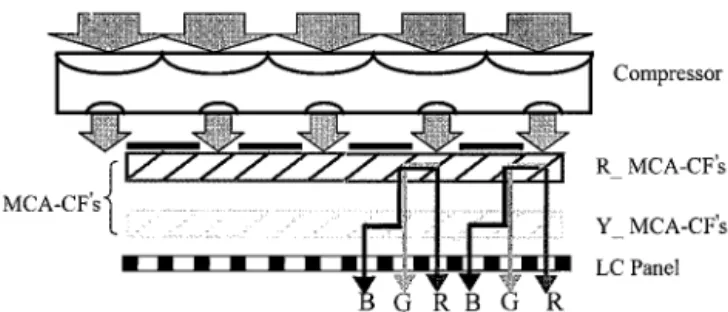
To increase the optical efficiency of the color filter and minimize the drawbacks mentioned above, an im-proved design, called HECF’s共2兲, is developed. It is composed of a microlens array light compressor and a stack of two layers of microcube array color filters 共MCA-CF’s兲. As shown in Fig. 2, the MCA-CF’s are composed of 45°–90°– 45° cube arrays and dichroic filters on the diagonal interfaces of the cubic arrays. Each cube constitutes a color subpixel. The diago-nal interface of each microcube is coated with a di-chroic filter to separate the spectra of incident light. In the upper layer of the microcube array, the di-chroic filters in the diagonal interfaces are coated as red filters and those in the lower layer are coated as yellow filters. The light compressor is a Galilean-telescope-type microlens array system whose magni-fication is one-third. The diameter of each lens is the same as the size of the whole triad, which in-cludes R, G, and B subpixels. The beam size of light from the illumination system is compressed one-third by the microlens array compressor and then is im-pinged on one cube of the first layer of the MCA-CF’s. Then the compressed light is split into transmitted red light and reflected complementary light by the red filters in the first-layer MCA-CF’s. The trans-mitted red beams directly transmit the second-layer yellow MCA-CF’s. The complementary light spectra are reflected to the adjacent microcube and then are rereflected by the red filter on the diagonal face. As a result the complementary light beams become nor-mally injecting toward the second-layer yellow MCA-CF’s. Similarly, the reflected light spectra from the first layer is split into green transmitted and blue reflected beams in the second-layer MCA-CF’s.
Fig. 1. Configuration and function of HECF’s共1兲: 共a兲 incident light on each pixel divided into three different spectra of R, G, and B;共b兲 light output of each pixel containing spectra derived from three respective pixels.
Fig. 2. Configuration and function of HECF’s共2兲: Incident light is compressed by the light compressor and then divided into three primary colors, R, G, and B, to the respective color’s subpixels.
Consequently the incident white light is split into three parallel light beams of primary colors, R, G, and B, who are distributed to the corresponding color pix-els, as shown in Fig. 2. Combining the effects of a telescope-type light compressor and the MCA-CF’s, the HECF can efficiently utilize the whole spectra of incident light and greatly increase the optical throughput. The light path can be maintained at normal in– out in this device, and the divergent angle of light in the system also remains. Moreover in HECF’s共2兲 the fabrication process of the dichroic-filter coating in MCA-CF’s is much easier than that in MPA-CF’s because of only one color of coating on each layer of MCA-CF’s.
3. Results and Discussion
To evaluate the functionality of HECF’s共1兲 and 共2兲, the MPA-CF’s in HECF’s共1兲 were fabricated by ce-menting the respective dichroic filter on the hypote-nuse face of each prism. Then the MCA-CF’s in HECF’s共2兲 were fabricated by cementing a series of glass rods of 45°–135° parallelogram cross section
and 4 mm ⫻ 5.6 mm ⫻ 40 mm dimension with a dichroic filter coated on the interface between each rod, as shown in Fig. 3共a兲. The transmitted spectra in the red and the yellow dichroic filters of 45° inci-dent angle were measured as shown in Fig. 4. The Galilean-telescope-type light compressor was fabri-cated in a plastic plate with two sets of cylindrical microlens arrays, one concave lens and the other con-vex, on both sides of the plate. The dimension of such lenses was 12 mm in width and 40 mm in length, compatible with the dimension of glass rods. To re-duce further the dimension of CF’s, the MCA-CF’s could be fabricated by a method of cementing two pieces of prism array with interference color fil-ters coated on the hypotenuse face of each prism, as shown schematically in Fig. 3共b兲.
The optical throughput and color purity of HECF’s were measured by a Minolta chromameter, XY-1, and a projection system, schematically shown in Fig. 5.
Fig. 3. Configuration of MCA-CF’s: A series of glass rods are cemented with an interference color filter coated on the interface between each rod.
Fig. 4. Measured spectra of red and yellow color filters in the MCA-CF’s.
Fig. 5. Configuration of measurement system with a Minolta chromameter, XY-1.
A metal-halide light source and a projection lens with an F number of 2.8 were used. The measured opti-cal throughputs were normalized to an incident brightness of 100 lx. The normalized optical throughputs of HECF’s共1兲 and 共2兲, shown in Fig. 6 for comparison with those of planar interference color filters, increased by more than a factor of 2 at each color subpixel. Consequently, the HECF’s can greatly improve the brightness in a projector.
Be-cause of the luminous efficiency function V共兲 of eyes, the visual optical throughputs of the blue and the red subpixels were much lower than those of the green subpixels. Moreover the efficiency can be further enhanced by increasing the transmittance of the red and the yellow MCA-CF’s with an improved spectra design and coating process and additions of antire-flected coating on the entrance兾exit surfaces of MCA-CF’s.
The experimental results in the chromaticity dia-gram with respect to three output primary colors, R, G, and B, of HECF’s共1兲 and 共2兲 and planar interfer-ence color filters is shown in Fig. 7. Because of the reutilization of the reflected light of interference color filters, the color purity of HECF’s共1兲 was not as good as that of planar interference color filters. By opti-mizing the spectra design of the red and the yellow filters, the color purity of HECF’s共2兲 can be as good as that of planar color filters. Since HECF’s reuse re-flected complementary spectra to improve optical ef-ficiency, there is a trade-off between optical throughputs and color purity for these color filters.
In a practical application the dimensions of the mi-croprism and microlens array light compressor should be further reduced. A binary Fresnel microlens fab-ricated with very-large-scale-integrated共VLSI兲 lithog-raphy and etching processes is easily mass produced with high accuracy. Electric-discharge machining7
and injection兾stamping molding are a way to produce microprism arrays. As shown in Fig. 8 we have fab-ricated a prototype microprism array of 2-mm pitch by injection molding with a master mold made by line electric-discharge cutting. To reduce the dimension of the microprism further to the order of 10 –100m, some advanced VLSI fabrication technologies, such as electron-beam direct write8 and gray-scale mask
li-thography,9,10are capable of producing such a
micro-optical structure. However, at these dimensions, some diffraction phenomena may occur at the corner of each structure. Producing a pixel-size microprism and coating high-quality red兾yellow interference fil-ters on a plastic substrate are in process, and results will be reported in the near future.
4. Conclusions
New structures of high-efficiency micro-optical color filters that can greatly increase the optical through-puts of single-panel LC projection systems have been
Fig. 7. Measured colorimetric coordinates of the CIE 1931 chro-maticity diagram of three primary colors of R, G, and B obtained from HECF’s共1兲 and 共2兲 and planar color filters, respectively. NTSC, National Television Systems Committee.
Fig. 8. Photography of a microprism array of 2-mm pitch.
Fig. 6. Optical efficiency of HECF’s共1兲 and 共2兲 and planar color filters.
presented. The proposed color filters, composed of microlens and microcube structures, enhance the brightness of a LCD projector because the light ab-sorbed by the conventional color filters is now di-rected to the corresponding color subpixels for illumination. The HECF’s compress the incident beam area into one-third with the microlens array light compressor and inject the compressed light into the corresponding microcube array color filters. Then the compressed light energy is fully distributed to the corresponding color subpixels, and whole vi-sual spectra energy is fully utilized. As a result the optical efficiency of color filters can be increased by more than a factor of 2, and the brightness of a single-panel-type LC projection system can be greatly im-proved.
This research was supported by the National Sci-ence Council, the Republic of China, under contract NSC 87-2215-E009-013.
References
1. C. M. Chang, K. W. Lin, K. V. Chen, S. M. Chen, and H. P. D. Shieh, “A uniform rectangular illumination optical system for liquid crystal light valve projectors,” in EuroDisplay ’96, Pro-ceedings of the Sixteenth International Display Research Con-ference 共Society for Information Display, Santa Ana, Calif., 1996兲, pp. 257–260.
2. H. Hamada, F. Funada, M. Hijikigawa, and K. Awane, “Bright-ness enhancement of an LCD projector by a planar microlens array,” in Society of Information Display ’92, Proceedings of the International Symposium 共Society for Information Display, Santa Ana, Calif., 1992兲, pp. 269–272.
3. M. F. Weber, “Retroreflecting sheet polarizer,” in Society of
Information Display ’92, Proceedings of the International Sym-posium共Society for Information Display, Santa Ana, Calif., 1992兲, pp. 427–429.
4. Y. Itoh, J.-I. Nakamura, K. Yoneno, H. Kamakura, and N. Okamoto, “Ultra-high-efficiency LC projector using a polarized light illuminating system,” in Society of Information Display ’97, Proceedings of the International Symposium共Society for Information Display, Santa Ana, Calif., 1997兲, pp. 993–996. 5. J. Fuhrmann, B. Sautter, T. Kallfass, and E. Lueder,
“En-hancement of the light efficiency of LC projection systems by the use of dichroic color filters,” in Society of Information Dis-play ’97, Proceedings of the International Symposium共Society for Information Display, Santa Ana, Calif., 1997兲, pp. 761–764. 6. J. C. Yoo, S. M. Chen, S. F. Chen, and H. P. D. Shieh, “Fabri-cation of thin film optical interference filters for LCD color filters,” Technical Report 共Institute of Electronics, Informa-tion, and Communication Engineers, Tokyo, Japan, 1994兲, Vol. 94, pp. 39 – 43.
7. T. Yuzawa, T. Magara, Y. Imai, and K. Kobayashi, “Microcon-tour EDM using thin electrode,” in Proceeding of the Spring Conference of the Japan Society of Precision Engineering 共Ja-pan Society of Precision Engineering, Tokyo, 1995兲.
8. W. Daschner, M. Larsson, and S. H. Lee, “Fabrication of mono-lithic diffractive optical elements by the use of e-beam direct write on an analog resist and a single chemically assisted ion-beam-etching step,” Appl. Opt. 34, 2534 –2538共1995兲. 9. W. Da¨schner, P. Long, R. Stein, C. Wu, and S. H. Lee, “Cost
effective mass fabrication of multilevel diffractive optical ele-ments by use of a single optical exposure with a gray-scale mask on high-energy beam-sensitive glass,” Appl. Opt. 36, 4675– 4680共1997兲.
10. T. J. Suleski and D. C. O’Shea, “Gray-scale mask for diffractive-optics fabrication: 1. Commercial slide imagers,” Appl. Opt. 34, 7507–7517共1995兲.