Dynamic stability control analysis of sandwich annular plate
with electrorheological core treatment
Jia-Yi Yeh
Department of Information Management, Chung Hwa University of Medical Technology.
E-mail : [email protected]
Abstract
The dynamic stability control analysis problems of sandwich annular plate with an electrorheological (ER) fluid core and constraining layer are investigated. In this study, the annular plate system is covered an ER fluid core and a constraining layer. And, the discrete layer annular finite element and the harmonic balance method are used to obtain the instability regions of the sandwich annular plate system. It can be observed that the damping effects of the system can be controlled when different electric fields are applied on the sandwich structures and the ER fluid core is found to have a significant effect on the location of the boundaries of the instability regions. Additionally, variations of the instability regions of the sandwich annular plate with different applied electric fields and thickness of ER layer are studied and discussed in this paper.
Keywords: dynamic stability, electrorheological, annular plate, discrete layer annular finite element.
1. Introduction
The ordinary forced response will lead to dynamic instability of the system under some circumstances when structures are subjected to periodic loads. The instability may occur under periodic loads over a range of excitation frequency and the induced violet vibration is called the parametric resonance or dynamic instability. A number of investigators have studied the parametric resonance due to the periodic in-plane loads and one of these is Bolotin [1]. The dynamic characteristics analyses of the plate structures had been widely investigated and studied in mechanical applications.
The dynamic instability of single circular and annular plates due to periodic in-plane stress systems had been studied and discussed by many researchers. Pardoen [2] investigated the vibration and buckling analysis of axisymmetric polar orthotropic circular plate. Tani and Doki [3] presented the parametric resonance analysis of polar orthotropic annular plate. And, Stevens [4] discussed the influence of initial curvature on the dynamic stability behaviors of the viscoelastic structures based on the complex modulus representation. Chen and Hwang [5] adopted the finite element and Galerkin methods to study the axisymmetric dynamic stability of isotropic and polar orthotropic thick circular plates. The parametric resonance characteristics analyses of the non-linear viscoelastic plate are studied and presented by Touati and Cederbaum [6]. Then, the vibration and dynamic stability of viscoelastic plates with isotropic viscoelastic constitutive relation was discussed by Ilyasov and Akoz [7].
The wide introduction about the applications of the ER material was presented by Weiss et al. [8] regarding the active control of the structural vibration to the use of the ER materials. Coulter [9] presented that the ER fluid has the same properties as a viscoelastic material at small strain level and the studies for the construction of smart components. The vibration behaviors of the sandwich beam with ER fluid core and the variations of the modal loss ©2010 National Kaohsiung University of Applied Sciences, ISSN 1813-3851
factors with different designed parameters of the sandwich system were investigated and discussed by Yalcintas and Coulter [10]. Then, Kang et al. [11] investigated the passive and active damping characteristics of the ER composite beams and also discussed the variations of the system caused by the designed parameters. And, the flexural vibration of laminated composite ER sandwich beams to maximize the possible damping capacity was also calculated in this study. Afterwards, the dynamic stability problems of the ER sandwich beam were presented by Yeh et al. [12] and they also discussed the dynamic characteristics of the sandwich beam with different thickness of the ER layer and applied electric filed.
2. Analytical Model and Calculation Method
As shown in Figure 1, the sandwich annular plate subjected with ER core layer and subjected to the uniform radial stress is demonstrated. Layer 1 is a pure elastic, isotropic constraining layer. The ER fluid core layer is designed as layer 2 and the properties of the ER material can be changed and controlled by applied different electric fields. The base annular plate is designated as layer 3 with an inner radius and outer radius and assumed to be undamped and isotropic. Besides, the thicknesses of the three layers of the sandwich annular plate system are
, , and , respectively.
a
b
1
h
h
2h
3Figure 1. The sandwich annular plate system subjected to the uniform radial stress.
Then, the strain-displacement relation of the elastic layer can be expressed in terms of the in-plane displacements of the adjacent layer interfaces and the transverse displacement as follows by considering the geometry of the sandwich annular plate as shown in Figure 1:
⎪ ⎭ ⎪ ⎬ ⎫ ⎪ ⎩ ⎪ ⎨ ⎧ = ⎭ ⎬ ⎫ ⎩ ⎨ ⎧ = + ) , ( ) , ( ) , ( ) ( ) , , ( ) , , ( 1 , 1 t r W t r U t r U z H t z r w t z r u d i i i i i i , (1)
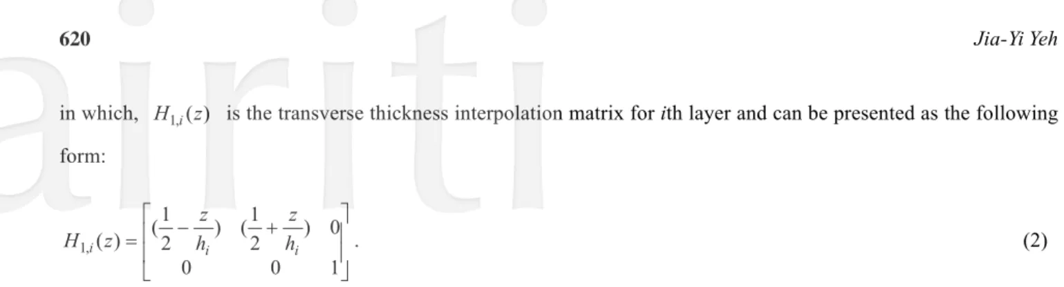
in which, is the transverse thickness interpolation matrix for ith layer and can be presented as the following form: ) ( , 1 z H i ⎥ ⎥ ⎦ ⎤ ⎢ ⎢ ⎣ ⎡ − + = 1 0 0 0 ) 2 1 ( ) 2 1 ( ) ( , 1i i hi z h z z H . (2)
The discrete layer annular finite element is adopted to model the problem as shown in Figure 2.
Figure 2. The discrete layer annular finite element for three-layer element.
Then, the displacements of the interfaces for two-layer can be shown in terms of the nodal degrees of freedom as following equation by using the interpolation in r-direction and the circumferential wave number m:
) ( ) ( ) , ( ) , ( ) , ( 2 1 H r q t t r W t r U t r U e i i i = ⎪ ⎭ ⎪ ⎬ ⎫ ⎪ ⎩ ⎪ ⎨ ⎧ + , (3)
where is the vector of the nodal
displacements of the element and is the interpolation matrix and listed as follows:
{
B B B}
T i B i B i B i A A A i A i A i A i e i U V U V W U V U V W q = +1 +1 Θ +1 +1 Θ ) ( 2 r H ⎥ ⎥ ⎥ ⎦ ⎤ ⎢ ⎢ ⎢ ⎣ ⎡ = Θ ΘA wB B A w B u A u B u A u r H φ φ φ φ φ φ φ φ 0 0 0 0 0 0 0 0 0 0 0 0 0 0 0 0 ) ( 2,
(4) where φA =(1−ξ),
,
,
,
,
,
u φuB =ξ φwA =(1−3ξ2+2ξ3) φwB =(3ξ2−2ξ3) φΘA=(ξ−2ξ2+ξ3) φΘB =(−ξ2+ξ3) i i r r r r − − = 0 ξ.
The strain-displacement relation for the ith layer of the system can be expressed as follows: = ⎪ ⎭ ⎪ ⎬ ⎫ ⎪ ⎩ ⎪ ⎨ ⎧ = i rz i i r i , , , ε γ ε ε θ Ddi, (5)
where εi is the strain vector and
⎥ ⎥ ⎥ ⎥ ⎥ ⎥ ⎦ ⎤ ⎢ ⎢ ⎢ ⎢ ⎢ ⎢ ⎣ ⎡ ∂ ∂ ∂ ∂ ∂ ∂ = r z r r D 1 0 0
is the differential operator matrix. Then, the stress-strain
relation can be obtained and can be shown as the following equation: i
i i Cε
σ = , (6)
where σi=
{
σr,i σθ,i τrθ,i}
T, and Ci is the elasticity matrix as shown in the follows:⎥ ⎥ ⎥ ⎦ ⎤ ⎢ ⎢ ⎢ ⎣ ⎡ = i i i i i i C C C C C C , 44 , 22 , 21 , 12 , 11 0 0 0 0 , (7)
for the isotropic material, 11, 22, 2 1 i i i i C E C υ − = = , 12, 21, 2 1 i i i i i C E C υ υ − = = , ) 1 ( 2 2 , 44 i i i E C υ κ + = , respectively. In the above equations, Ei is the Young’s modulus, υ is the Poisson ration, and i κ2 is the shear correction factor. Besides, for layer 1 and layer 3, the shear correction factor is taken to be π2 12, while to be 1 for layer 2.
Afterwards, the strain and kinetic energies of the element for ith layer can be expressed as:
∫
∫
+ = V i V i e i dV dV V T i i Tε ε 2 1 σ σ , (8)∫
= V i e i ρ dV T uTiui 2 1 & & , (9)in which, σ , i ε , and i ρ are external load stress vector, non-linear strain vector, and the mass density of the ith i layer, respectively. Besides, the second term in equation (8) is additional strain energy due to external in-plane loads.
By substituting the above equations into equation (8), (9) and Hamilton’s principle, the element dynamic equilibrium equation can be obtained and express as:
0 U ) G K ( U M + + e = i e i e i e i e i && , (10)
where , , and are element mass matrix, element stiffness matrix, and element geometric stiffness matrix due to the external in-plane load, respectively.
e i
The following relations should be obtained for combining the elemental matrices into the global stiffness and mass matrices:
U Tr
Uei = ie , (11)
where U and Trie are the global nodal co-ordinate vector and transformation matrix, respectively.
Then, the equation of motion for the sandwich system can be express as the following equation by assembling the contribution of all elements of the system:
0 U ) G K ( U M&&+ + = , (12)
where M, K, G are global mass, global stiffness, and global geometric stiffness matrix due to the external in-plane load, respectively.
After that, the external load stress,P(t), is assumed to be a periodic radial stress and presented as follows:
t P P t
P()= 0+ tcosΘ , (13)
where , , and are static load factor, dynamic load factor, and the disturbance frequency, respectively. Additionally, the geometric stiffness matrix can be rewritten as the following form:
0 P Pt Θ t t Θ + =G G cos G 0 , (14)
in which, is the static geometric stiffness matrix and is dynamic geometric stiffness matrix. Then, the equation can be expressed as the following form called Mathieu-Hill equation:
0 G Gt 0 U ) cos G G K ( U M&&+ + 0+ t Θt =
.
(15)In this study, the boundary of the dynamic instability can be calculated and obtained by using Bolotin’s method [1]. The boundary of the dynamic instability of the sandwich system is formed according to the periodic solutions of the T (2π/Θ) and 2T (4π/Θ). The boundary of the primary instability region with period 2T is of practical important in mechanical applications and the solution can be expressed as follows:
⎥⎦ ⎤ ⎢⎣ ⎡ Θ + Θ = 2 cos } { 2 sin } { ) ( Ut a1 t b1 t , (16)
and period solution with a period T in the form
[
{ }sin( ) { }cos( )) (
Ut = a2 Θt + b2 Θt
]
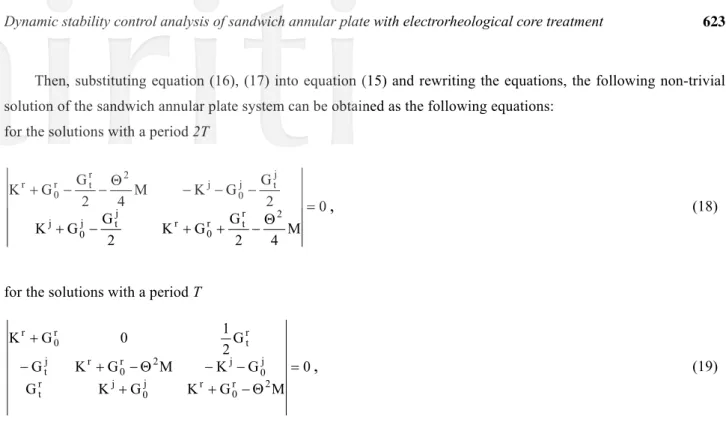
, (17)Then, substituting equation (16), (17) into equation (15) and rewriting the equations, the following non-trivial solution of the sandwich annular plate system can be obtained as the following equations:
for the solutions with a period 2T
0 M 4 2 G G K 2 G G K 2 G G K M 4 2 G G K 2 r t r 0 r j t j 0 j j t j 0 j 2 r t r 0 r = Θ − + + − + − − − Θ − − +
,
(18)for the solutions with a period T
0 M G K G K G G K M G K G G 2 1 0 G K 2 r 0 r j 0 j r t j 0 j 2 r 0 r j t r t r 0 r = Θ − + + − − Θ − + − +
,
(19)where the superscripts r and j denote the real and imaginary part of the matrices, respectively. Eauqtions (18) and (19) are the equations of the boundary frequencies and the stability-instability boundaries of the sandwich system can be obtained by solving the equations.
3. Results and Discussions
The solutions of natural frequencies and loss factors of the sandwich annular plate with a viscoelastic layer by present method are obtained in order to validate the proposed algorithm and calculations. The numerical results are compared with those results calculated by Roy and Ganesan [19]. And, the numerical solutions solved by present model are shown to have a good agreement and accuracy. Afterwards, for convenience, the following non-dimensional parameters and some geometrical parameters are introduced:
m b=0.15 , b a a~= , E1=E3=70GPa , υ1=υ3=0.29, υ2 =0.49, , , , 3 3 1=ρ =2700kg/m ρ 3 2 =1700kg/m ρ mm h3=0.5 h23=h2 h3 , h13 =h1 h3 , ) 1 ( 12 2 3 2 3 3 υ − = Eh Dk , k o D b h P K 2 3 0 − = , k t t D b h P K 2 3 − = . Additionally, the boundary conditions are simply-supported and the number of elements in the r-direction is taken to be 16 in the following discussions.
Table 1. Comparison between published and proposed methods for the full coverage annular plate. Boundary condition: Clamped at inner edge and free at outer edge. (K0=0,Kt =0)
Natural frequency (Hz) Modal loss factor (%) Mode
(n, m)
Proposed Roy and Ganesan [13]. Proposed Roy and Ganesan [13].
(0,0) 74.44 74.38 11.28 11.27
(0,1) 73.00 73.08 9.542 9.576
(0,2) 96.20 96.38 10.16 10.21
(0,3) 144.0 142.8 12.10 12.12
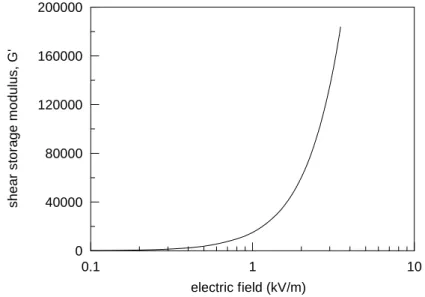
The damping effects of the sandwich system are provided by the ER fluid in this study, and only the electric field dependence of ER fluid needed to consider based on the existing model of ER material. Therefore, the complex modulus of ER fluid can be simplified into the following form, which was experimentally calculated by Don [14]: G j G E G2( *)= ′+ ′′, (20)
where G′ is the shear storage modulus, G ′′ is the loss modulus (G′′≈6900), is the applied electric field in
kV/mm, and * E 1 − =
j , respectively. And, the variations of the shear storage modulus with different applied electric fields are shown in Figure 3.
0.1 1 10 electric field (kV/m) 0 40000 80000 120000 160000 200000 shea r st or a g e mod u lu s, G'
Figure 3. Shear storage modulus dependence on electric fields for the ER material.
The effects of dynamic load parameter on the first two instability regions of the sandwich annular plate system with various applied electric fields are plotted in Figure 4(a) and (b), respectively. And, the relative parameters of the system are
t K 1 . 0 ~ =
a , h13=0.1, h23=0.5, andKo =1. According to the numerical results, the variations of first two instability regions of the sandwich annular system can be observed and it can be found that the instability regions will move rightwards as the applied electric fields increase.
32 36 40 44 48 52 Θ 0 0.4 0.8 1.2 1.6 2 Kt 0.5kV/mm 1.0kV/mm 2.0kV/mm 16 18 20 22 24 Θ 0 0.4 0.8 1.2 1.6 2 Kt 0.5kV/mm 1.0kV/mm 2.0kV/mm
(a) first instability regions (b) second instability regions Figure 4. Effects of dynamic load parameter Kt on the instability region with various applied electric fields.
Additionally, the tip of first two instability regions of the sandwich system will also move downwards with the increasing of the applied electric fields. It is because that the applied electric fields will change the material characteristics of the ER core layer. And, the stiffness of the sandwich annular plate system will increase as the applied electric fields increase.
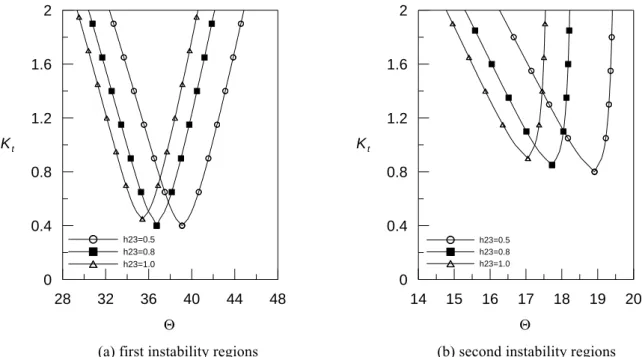
Figure 5 (a) and (b) show the effects of dynamic load parameter on the first two instability regions of the sandwich annular plate system with various thickness of ER core layer.
t K 28 32 36 40 44 48 Θ 0 0.4 0.8 1.2 1.6 2 Kt h23=0.5 h23=0.8 h23=1.0 14 15 16 17 18 19 20 Θ 0 0.4 0.8 1.2 1.6 2 Kt h23=0.5 h23=0.8 h23=1.0
(a) first instability regions (b) second instability regions
And, the relative parameters of the system are ~ =a 0.1, h13=0.1, E*=0.5kV/mm, and Ko =1. The instability region of the sandwich plate system will move leftwards and upward when the thickness of ER layer increases. Additionally, the tips of the instability region will move backward as the damping effects increase. It is because that the damping effects are controlled by the ER core layer and can be changed by applying different electric fields. Besides, the variations of the instability region are the same and more significant according to the numerical results.
Finally, the first two instability regions of the sandwich annular plate system with different boundary conditions (simply-supported and clamped-free) are presented in Figure 6. And, the relative parameters of the system are
1 . 0 ~ =
a , h13=0.1, h23=0.5, E*=0.5kV/mm, andKo =1. The boundary conditions will also affect the instability regions of the sandwich system according to the results. The S-S boundary conditions will obtain larger excitation frequency than C-F boundary conditions, and the tendency is similar for first two instability regions of the sandwich annular plate system.
28 32 36 40 44 48 Θ 0 0.4 0.8 1.2 1.6 2 Kt C-F S-S 15 16 17 18 19 20 Θ 0 0.4 0.8 1.2 1.6 2 Kt C-F S-S
(a) first instability regions (b) second instability regions Figure 6. Effects of dynamic load parameter Kt on the instability region with different boundary conditions.
4. Conclusions
In this study, the dynamic stability problems of the sandwich annular plate with an ER fluid core layer are investigated and discussed. There are no works have done to investigate the parametric resonance problem of the sandwich annular plate with ER fluid core layer to the author’s knowledge. The boundaries of the instability regions of the sandwich annular plate are calculated and obtained by using the discrete layer annular finite element method and the harmonic balance method. The following conclusions can be obtained according to the numerical results. At first, it can be seen that the applied electric fields will change the stiffness of the annular sandwich plate, and boundaries of the instability regions of the system can be changed when applying different electric fields. And, the boundaries of the instability regions of the sandwich annular plate system will be changed and controlled with various thickness of the ER layer. Finally, the ER materials are shown to have significant effects on the instability regions of the sandwich structures and can be changed by applying different electric fields.
*
E
Reference
[1] Bolotin V.V., “The dynamic stability of elastic system,” Holden-Day San Francisco, 1964.
[2] Pardoen G.C., “Vibration and buckling analysis of axisymmetric polar orthotropic circular plates,” Computers and Structures, Vol. 4, pp. 951-960, 1970.
[3] Tani J. and Doki H., “Dynamic stability of orthotropic annular plates under pulsating redial loads,” Journal of the Acoustical Society of America, Vol. 69, pp. 1688-1694, 1982.
[4] Stevens K.K., “Transverse vibration of a viscoelastic column with initial curvature under periodic axial load,” Journal of Applied Mechanics, Vol. 36, pp. 814-818, 1969.
[5] Chen L.W. and Hwang J.R., “Axisymmetric dynamic stability of polar orthotropic thick circular plates,” Journal of Sound and Vibration, Vol. 125, pp. 555-563, 1988.
[6] Touati D. and Cederbaum G., “Dynamic stability of nonlinear viscoelastic plates,” International Journal of Solids and Structures, Vo. 31, pp. 2367-2376, 1994.
[7] Ilyasov M.H. and Akoz A.Y., “The vibration and dynamic stability of viscoelastic plates,” International Journal of Engineering Science, Vol. 38, pp. 695-714, 2000.
[8] Weiss K.D., Coulter J.P. and Carlson J.D., “Material aspects of electro-rheological system,” Journal of Intelligent Material Systems and Structures,.Vol. 4, No. 1, pp. 13-34, 1993.
[9] Coulter J.P., “Engineering application of electrorheological materials,” Journal of Intelligent Material Systems and Structures, Vol. 4, pp. 248-259, 1993.
[10] Yalcintas M. and Coulter J.P., “Electrorheological Material Based Adaptive Beams Subjected to Various Boundary Conditions,” Journal of Intelligent Material Systems and Structures, Vol. 6, pp. 700-717, 1995.
[11] Kang Y.K., Kim J. and Choi S.B., “Passive and active damping characteristics of smart electro-rheological composite beams,” Smart Materials and. Structures, Vol. 10, pp. 724-729, 2001.
[12] Yeh J.Y., Chen L.W. and Wang C.C., “Dynamic stability of a sandwich beam with a constrained layer and electrorheological fluid core,” Composite Structures, Vol. 64, pp. 47-54, 2004.
[13] Roy P.K. and Ganesan N., “A vibration and damping analysis of circular plates with constrained damping layer treatment,” Computers and Structures, Vol. 49, pp. 269–274, 1993.
[14] Don D.L., “An investigation of electrorheological material adoptive structures,” Master’s Thesis Lehigh University, Bethlehem, Pennsylvania, 1993.