852 IEEE MICROWAVE AND WIRELESS COMPONENTS LETTERS, VOL. 17, NO. 12, DECEMBER 2007
A Compact Ultra-Wideband Bandpass
Filter Based on Split-Mode Resonator
Tsung-Nan Kuo, Chi-Hsueh Wang, and Chun Hsiung Chen, Fellow, IEEE
Abstract—A compact ultra-wideband (UWB) bandpass filter is proposed based on the coplanar-waveguide (CPW) split-mode res-onator. By suitably introducing a short-circuited stub to implement the shunt inductance between two quarter wavelength( 4) CPW stepped-impedance resonators, a strong magnetic coupling may be realized so that a CPW split-mode resonator may be constructed. Moreover, by properly designing the dual-metal-plane structure, one may accomplish a microstrip-to-CPW feeding mechanism to provide strong enough capacitive coupling for bandwidth enhance-ment and also introduce an extra electric coupling between input and output ports so that two transmission zeros may be created for selectivity improvement. The implemented UWB filter shows a fractional bandwidth of 116% and two transmission zeros at 1.705 and 11.39 GHz. Good agreement between simulated and measured responses is observed.
Index Terms—Bandpass filter (BPF), coplanar waveguide (CPW), dual-plane structure, microstrip, split-mode resonator, ultra-wideband (UWB).
I. INTRODUCTION
T
HE ultra-wideband (UWB) wireless communication tech-nology has received great attention, especially after the Federal Communications Commission (FCC) decision to permit the unlicensed operation band from 3.1 to 10.6 GHz in February 2002 [1]. The UWB systems have many attractive benefits such as transmitting higher data rates and requiring lower transmit power. However, for developing the UWB filters, there are a lot of challenges to meet the ultra-wide bandwidth requirement.Over the past few years, the optimum distributed highpass filter prototype [2] was adopted to design the UWB filters. To reduce the circuit size, the technique of using folded lines and shared vias was employed to implement the UWB filters [3]. To further increase the selectivity, a cross coupling between feeding lines was added to create new pairs of transmission zeros [4]. Furthermore, to suppress the spurious response, elec-tromagnetic bandgaps were adopted in [5]. However, these fil-ters have the drawbacks of large circuit area and inconvenient via process.
Manuscript received May 24, 2007; revised August 1, 2007. This work was supported in part by the National Science Council of Taiwan, R.O.C., under Grant NSC 95-2752-E-002-001-PAE, Grant NSC 95-2221-E-002-196 and in part by the Excellent Research Projects of National Taiwan University, NTU-ERP-95R0062-AE00-00.
The authors are with the Department of Electrical Engineering and Graduate Institute of Communication Engineering, National Taiwan University, Taipei 106, Taiwan, R.O.C. (e-mail: [email protected]).
Color versions of one or more of the figures in this paper are available online at http://ieeexplore.ieee.org.
Digital Object Identifier 10.1109/LMWC.2007.910483
Multiple-mode resonator is another popular structure used for wideband filter design. In [6], the aperture compensation technology was proposed to increase the coupling between par-allel-coupled lines. In [7], a five-pole UWB filter was built up based on a single triple-mode stepped-impedance resonator. In [8], the microstrip-to-CPW transition was used as a feeding structure. Since these filters are based on the half-wavelength 2 multiple-mode resonators, they have large circuit sizes and poor selectivity.
Recently, dual-plane structures have become a competitive candidate for the filter design. In [9], the wideband filters using microstrip and CPW quarter-wavelength 4 resonators were reported, however their bandwidths are not wide enough to meet the UWB requirement. In [10], the UWB filters based on the quasi-lumped-circuit elements were proposed. Although these filters possess good performances and compact sizes, their spu-rious passbands are close to the UWB passband.
In this letter, a compact UWB bandpass filter (BPF) based on the split-mode resonator is fabricated. The split-mode res-onator is formed by introducing a CPW short-circuited stub into two 4 CPW stepped-impedance resonators. By properly de-signing the split-mode resonator, the upper spurious passband may somewhat be suppressed. To accomplish a large capaci-tive coupling, the broadside-coupled microstrip-to-CPW tran-sitions are adopted as the feeding structures for bandwidth en-hancement. Moreover, an extra electric coupling between input and output ports is introduced to create two transmission zeros for selectivity improvement. Specifically, the implemented four-pole UWB filter has the merits of compact size, good inser-tion/return loss, improved selectivity, flat group delay, and better upper stopband response.
II. FOUR-POLEUWB FILTER
A. Split-Mode Resonator
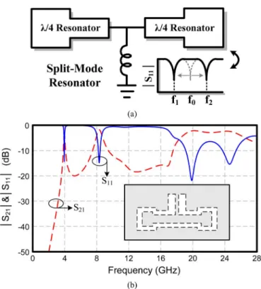
Fig. 1 shows the proposed four-pole UWB filter using both microstrip and CPW structures. The proposed filter is based on the CPW mode resonator. As shown in Fig. 2(a), the split-mode resonator is composed of two 4 stepped-impedance res-onators and each resonator is resonated at the central frequency . By introducing a shunt inductance to establish a strong mag-netic coupling between two 4 resonators, one may implement a split-mode resonator which has two split resonance frequen-cies at and . Specifically, the larger the inductance, the stronger the coupling, the wider the split of two resonance fre-quencies, and the deeper the minimum in the curve. Further-more, it should be noted that the electric lengths of these two resonators may be reduced by the introduction of inductance.
1531-1309/$25.00 © 2007 IEEE
KUO et al.: COMPACT ULTRA-WIDEBAND BANDPASS FILTER 853
Fig. 1. Three-dimensional physical layout of the proposed four-pole UWB filter.
Fig. 2. Circuit structure and simulated responses of proposed CPW split-mode resonator.
To avoid using lumped-elements and metal vias, the CPW short-circuited stub is used to realize the shunt inductance. Under the ultra-wide bandwidth requirement, the CPW short-circuited stub must be designed so as to widely separate the two split resonance frequencies. By combining the two 4 CPW resonators and the short-circuited stub, a CPW split-mode resonator is implemented. To investigate the reso-nance frequencies associated with the split-mode resonator, the simulator ADS Momentum is used. Fig. 2(b) shows the sim-ulated -parameters of the CPW split-mode resonator which is weakly coupled to the feeding structure. The simulated responses show that two split resonance frequencies and are observed at 4 and 8.3 GHz. Moreover, due to the use
Fig. 3. Simulated frequency responses of the filter with transitions of various microstrip length w.
Fig. 4. Top-/bottom-layer circuit layouts of the proposed four-pole UWB filter. (w = 1.905 mm, w = 2.794 mm, w = 0.889 mm, w =0.381 mm, w = 0.762 mm,d = 1.194 mm, d = 0.762 mm, d3 = 1.905 mm, d = 1.27 mm, d = 2.54 mm, d = 0.508 mm, and d = 2.794 mm).
o 4 stepped-impedance resonator which makes the spurious passband beyond the triple center frequency, higher unwanted resonances appear around 19.87 and 24.61 GHz. Note that these higher unwanted resonances would dominate the spurious passband of the proposed UWB filter.
B. Transition and Extra Electric Coupling
Strong couplings in input and output stages are required in designing a broadband filter. In this study, to fit in with the UWB requirement, the broadside-coupled microstrip-to-CPW transitions are adopted as the input/output feeders so as to provide strong enough capacitive couplings for bandwidth enhancement. Here, the simulated responses associated with the transition structure are illustrated in Fig. 3. By increasing the microstrip length w (Fig. 3) to increase the overlap area between microstrip and CPW, the insertion loss around the minimum is reduced and becomes smooth.
Based on the magnetic coupling provided by the split-mode resonator, it is easy to create two transmission zeros at the lower and upper stopbands by introducing an extra electric coupling between the input and output ports. Taking advantages of the dual-metal-plane layout, the required electric coupling may be implemented by introducing the microstrip stubs of length
as shown in Fig. 4. Fig. 4 shows the top-/bottom-layer circuit layouts of the proposed UWB filter. The effect of adjusting the microstrip stub length , which controls the electric coupling level, is illustrated in Fig. 5. Specifically, the lower and upper transmission zeros will move close to the passband edge as the stub length is increased.
854 IEEE MICROWAVE AND WIRELESS COMPONENTS LETTERS, VOL. 17, NO. 12, DECEMBER 2007
Fig. 5. Curves to relate the transmission-zero frequencies to the values of the microstrip lengthd specified in Fig. 4.
Fig. 6. Measured and simulated results of the proposed four-pole UWB filter (Fig. 4). (a) Scattering parameters. (b) Group delay.
C. Measurement and Simulation Results
Fig. 6(a) shows the measured and fullwave simulated fre-quency responses of the four-pole UWB filter (see Fig. 4), which is fabricated on the Rogers RO4003C substrate with 3.38, tan 0.002, and thickness 0.508 mm. The measured center frequency is at 6.8 GHz and the measured 3-dB fractional bandwidth is 116 %. The implemented filter has an insertion loss better than 0.53 dB and a return loss greater than 11 dB within the passband. Two transmission zeros are found at 1.705 and 11.39 GHz and no spurious passband is observed from 12 to
19 GHz. Moreover, the simulated return loss shows that the pro-posed filter has four poles. The extra two poles are contributed by the input and output feeding structures [6].
Fig. 6(b) exhibits a flat group delay response below 0.51 ns over the whole passband. The four-pole UWB filter has a com-pact dimension of 9.625 mm 4.375 mm, which is approxi-mately 0.36 0.167 , where is the guided wavelength of microstrip structure at the center frequency of 6.8 GHz.
III. CONCLUSION
In this letter, a four-pole UWB filter based on the CPW split-mode resonator has been realized and carefully examined. The split-mode resonator is implemented by the CPW structure and has two split resonance frequencies in the UWB pass-band. By the dual-metal-plane layout, the broadside-coupled microstrip-to-CPW transitions and extra electric coupling may be incorporated in the filter design so that a compact UWB filter may be implemented with two transmission zeros created for selectivity improvement. Note that the implemented UWB filter has no spurious passband from 12 to 19 GHz, since the spurious harmonics of split-mode resonator have moved up to the higher frequencies. Compared to our previous work [10], this four-pole UWB filter has better performance than the three-pole one and more compact size than the five-pole one. The implemented filter has the merits of compact size and better performance when compared with the previously fabricated UWB filters.
REFERENCES
[1] Federal Communications Commission, Revision of Part 15 of the Commission’s Rules Regarding Ultra-Wideband Transmission Sys-tems FCC, Tech. Rep., ET-Docket FCC02-48, Feb. 2002, pp. 98–153. [2] J. S. Hong and M. J. Lancaster, Microstrip Bandpass Filters for
RF/Mi-crowave Applications. New York: Wiley, 2001, ch. 6.
[3] W. T. Wong, Y. S. Lin, C. H. Wang, and C. H. Chen, “Highly selective microstrip bandpass filters for ultra-wideband (UWB) applications,” in
Proc. Asia-Pacific Microw. Conf, Nov. 2005, pp. 2850–2853.
[4] H. Shaman and J. S. Hong, “A novel ultra-wideband vandpass filter with pairs of transmission zeros,” IEEE Microw. Wireless Compon.
Lett., vol. 17, no. 2, pp. 121–123, Feb. 2007.
[5] J. G. Garcia, J. Bonache, and F. Martin, “Application of electromag-netic bandgaps to the design of ultra-wide bandpass filters with good out-of-band performance,” IEEE Trans. Microw. Theory Tech, vol. 54, no. 12, pp. 4136–4140, Dec. 2006.
[6] L. Zhu, H. Bu, and K. Wu, “Aperture compensation technique for in-novative design of ultra-broadband microstrip bandpass filter,” in IEEE
MTT-S Int. Dig., 2000, pp. 315–318.
[7] L. Zhu, S. Sun, and W. Menzel, “Ultra-wideband (UWB) bandpass fil-ters using multiple-mode resonator,” IEEE Microw. Wireless Compon.
Lett., vol. 15, no. 11, pp. 796–798, Nov. 2005.
[8] H. Wang, L. Zhu, and W. Menzel, “Ultra-wideband bandpass filters with hybrid microstrip/CPW structure,” IEEE Microw. Wireless
Compon. Lett., vol. 15, no. 12, pp. 844–846, Dec. 2005.
[9] T. N. Kuo, S. C. Lin, C. H. Wang, and C. H. Chen, “Compact bandpass filters based on dual-plane microstrip/coplanar-waveguide structure with quarter-wavelength resonators,” IEEE Microw. Wireless Compon.
Lett., vol. 17, no. 3, pp. 178–180, Mar. 2007.
[10] T. N. Kuo, S. C. Lin, C. H. Wang, and C. H. Chen, “Compact ultra-wideband bandpass filters using composite microstrip-coplanar-wave-guide structure,” IEEE Trans. Microw. Theory Tech., vol. 54, no. 10, pp. 3772–3778, Oct. 2006.