1
納米級陶瓷粉體膠粒性質與形成鎳基複合電鍍材料之特性分析(1/2)
Analysis on Colloidal Properties of Nano-Sized Ceramic Powder and
Material Properties of Electro-Plated Ni-Based Composite Layer
計畫編號:NSC 89-2216-E-002-016
執行期間 88/08/01 89/07/31
主持人:韋文誠 國立台灣大學材料科學與工程學研究所
中英文摘要
本次研究主要分析超微細碳化矽粉體在胺基磺酸鎳鍍液中的的表面性質及帶電行為,瞭解碳化矽電泳動行 為,並進行後續複合電鍍。研究中發現,平均粒徑 62 nm 的碳化矽粉體在氯化鎳或胺基磺酸鎳的溶液中,粉體表面 都會吸附 Ni2+離子而帶正電。此外,在高濃度的電解質的電鍍液中,由於碳化矽表面電雙層被壓縮,其表面電位很 低,但仍維持正電荷表面。溶液中過高的 pH 會使 Ni2+形成水合的 Ni(OH) 2 沈澱物,降低碳化矽表面電位。經由複合電鍍,SiC 粉體成功的與鎳形成複合鍍膜,從 SEM 與 TEM 微結構觀察中發現,碳化矽形成軟聚結,但能均勻的分
散在鎳的基底中,並抑制鎳晶粒的成長,鎳形成 150 nm 的等軸狀晶。其硬度較純鎳提升 2 倍。經過 400°C,24 小
時的熱處理後,SiC/Ni 複合鍍層的耐磨耗性較純鎳提升約 50 倍。
This research investigated the electrokinetic behavior and stability of nano-sized SiC particles suspended in various electroplating solutions. Then, SiC powders electrical co-deposited with Ni in a sulfamate bath to form composite coatings. The negative surface of SiC in pH 4~8 will adsorb the Ni2+ ions in the suspensions which contain nickel chloride or nickel sulfamate as electrolytes and the surface charge of SiC reverse to positive. In high concentrated electrolyte of nickel sulfamate suspension, the SiC particles can still maintain positive charge with a low SC reading. The microstructure and mechanical analysis appear that the SiC particles can codeposition with Ni uniformly. The grain growth of Ni in the matrix can be inhibited by the SiC to form a uniaxial grain of 150 nm in average. The hardness and wear resistance of the plating layers are improved by the addition of the SiC and the thermal resistance significantly increases compared with blank sample.
1. Introduction
Ceramic processing of nano-sized powder has recently received increasing attention due to various advantages.[1] But the ultra-fine powders with high specific surface area have a cumbersome property, agglomeration often occur. In the aqueous or non-aqueous colloidal system, dispersion of these ultra-fine powders is one of the key steps to improve the mechanical properties of the composites prepared by slip casting, electrophoretic deposition (EPD) or composite electro-plating. According to DLVO theory [2], the van der Waal attractive force and the electrostatic repulsive force are two important interaction forces. If the surface charge of the powders can be increased, then a well dispersive suspension can be easily obtained. Therefore, a uniform dispersive composite and non-agglomerated bulk green body can be obtained.
In the aqueous solutions, the interface chemistry will great influence the colloidal properties, Whitman et al.[3]
use several kinds of silicon nitride and silicon carbide powders to measured the iso-electric point (IEP) in the same conditions. The surface adsorption or desorption species caused the IEP of Si3N4 powder varied from pH 3 to 9 depending on the powders synthesis procedure. Trace amount of contamination will change the surface charge in the aqueous suspension. Tartaj et al.[4] used SiC powder containing excess-carbon on the surface. The ultrapure SiC or excess carbon contained surface is hydrophobic behavior. When the surface is oxidized to have a silica layer, an increase of the stability of the suspension is
achieved.
Wang and Wei [5] showed that the addition of polyethyleneimine (PEI) could disperse submicron SiC powder in aqueous or alcoholic solution. PEI increased the pH of the suspension and the adsorption reaction of PEI chain on SiC reversed the surface charge of SiC from negative to positive. Therefore, the IEP of SiC powders shifted from pH 3.2 to pH 10.1 in the solution with dissolved PEI. Similar attempt was done by Iskra,[6] who used various ionic compounds to float coarse SiC powder with sizes of 75-150 µm. He found that the chemical dodecyclamine could also adsorbed on the surface of the SiC particles and changed the IEP from pH 2.8 to 10.
Composite coatings or electrolytic co-depositions are prepared by dispersing insoluble ceramic, polymeric or metallic powders in an electroplating solution during metal electroplating. The simultaneous deposition of the inclusions and metal phase to form the composite coating results in a great improvement of physical and mechanical properties. Recently, it needs technical breakthrough to apply the harden layer co-deposited composite on the cylinder surface of a hot engine [7], the surface coating of a cooling Cu mold for continuous casting of molten steel or the stamper of the CD and DVD.
For a SiC/Ni composite layer, the hardness and tribological properties of the composite layer can be improved by the intrinsic abrasive properties of SiC. Besides that, the hard particle is also improved by the dispersively strengthening mechanism.[8] The hard inclusions can inhibit the movement of grain boundaries of
Ni grains and retard the grain growth during thermal treatment. When the material suffers an external stress, the inclusions hinder the dislocation movement in metallic matrix[8], a plastic deformation becomes difficult. Therefore, the hardness of the composite layer increases and the wear resistance can be improved. Moreover, the wear resistance can also be improved by reducing the grain size of the metal matrix which includes ceramic particles.[9] The combined effects occur and can be enhanced by using nano-particles in electro-plating composites. According to Orowan’s report, the mechanism [8] for dispersive hardening occurred in composite system, the lowest stress (τ0) required to force the dislocation moving between the particles is
λ
τ0 =Gb (1)
where G is the shear modulus, b is the Burgers vector of the dislocation tied with two particles and theλis the distance between two particles. As the λ reduces when the number of hard inclusion increases and the inclusion particles uniformly disperse, a hardening composite coating can be prepared.
2. Exper imental Procedure
A plasma-synthesized SiC powder (PJ-PL-SiC, PlasmaChem, GmbH, German) of ultra-fine particle size was used in this study. A nickel sulfamate bath containing 90 g/l nickel sulfamate (Phibrochem Inc., USA), 3 g/l nickel chloride (EP grade, SHOWA, Japan), 40 g/l boric acid (EP grade, SHOWA, Japan) and a suitable wetting agent 3 ml/l was used. The cathode was a copper plate with dimensions of 10×6.5×0.25 mm and the anode was Ti basket containing small nickel ingots. A sequence of cleaning and acidic etching of the Cu plate by diluted sulfuric acid was applied before electro-plating.
The electrolyte, nickel sulfamate (Ni(SO3NH2)2, Phibrochem Inc., USA), nickel chloride (NiCl2, EP grade, SHOWA, Japan) was prepared. The suspensions were exposure to a ultrasonic probe (RK103 Sonorex, Taiwan, 35 kHz, 150W) for 10 min and those pH of the suspension was recorded before and after the measurement to observe the reaction of the suspension. The temperature of all suspensions was kept constant at 25±1 °C. Unless specified in the text, 0.01M NaC1 (Reagent grade, Nacalai tesque Inc., Kyoto, Japan) was added in suspensions to maintain the same ionic strength prior the addition of the powders.
For the composite plating, the solid loading of added powder in plating solution was 1 vol% based on the bath volume. Stirring of suspension by air bubbles kept the solution dispersive well. The current density was 4 Amp/dm2 (ASD). The bath temperature was controlled at 50±2°C and the pH ranged from 4.0 to 5.0, which was adjusted by H3BO3 or NaHCO3.The particle size was measured by particle size analyzer (Mastersizer 2000, Malvern Instruments, UK) and TEM (100CXII, JEOL, Japan). While the particle size analysis, a suitable dispersant of 2 vol% (base on solution) of polyethyleneimine (PEI, Scientific polymer products, Inc.,
Japan) was added into the suspension and ultrasonicated for 30 min to reduce the agglomeration and well dispersed the suspensions. The pH of suspensions was adjusted by regent grade 0.1M HCl or NaOH solution.
A electrophoresis mobility meter (Laser Zetameter 501, Pen Ken Inc., NY, USA) and an electrokinetics charger analyzer (ECA2000 Chemtrac Systems Inc., USA) were used for the measurement of ζ-potential and streaming current (SC) readings, respectively.
Crystalline phases of the composite layers were identified by X-ray diffractometry (XRD, Philips PW1792, Philips Instrument, Netherlands). The codeposition layer was examined with scanning electron microscopy (SEM, XL30 Philips, Netherlands) and TEM (TEM, JEOL 100CXII, Japan)
The hardness of the cross section of plating layer was measured by a Vicker’s indentor (AKASHI, MVK-EII, Japan) with a load of 50 gf and the indentation was lasted for 15 s. The tribological properties of the composite layer, including wear resistance and friction coefficient, were measured by a block-on-wheel method (TE53, Plint & Partiners Ltd., England). The wearing wheel was made by a heat-treated steel (NSOH/B01) with a hardness 65HRc.
3. Results and Discussion
3.1 The char acter ization of the powder
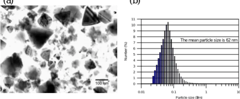
The morphology of the ultra-fine SiC powder observed by TEM is shown in Fig. 1(a). The shape of the SiC is angular for nano-sized particles, and nearly triangular for some sub-micron particles. The particle size is a Gaussian distribution and shown in Fig. 1 (b). The mean particle size of the as-received powder is 62 nm. The major phase of the SiC identified by XRD is 6H (α phase) and minor phase is 3C (β phase)
(a) (b)
Fig. 2 Variation of zeta-potential and streaming current readings of SiC with pH in diluted suspension.
Fig. 1 (a) The TEM micrograph of nano-sized SiC and (b) the particle size distribution of SiC, 2 vol% of PEI was added as a dispersant 0.01 0.1 1 10 Particle size (µm) 0 1 2 3 4 5 6 7 8 9 10 11 N u m b e r (%
) The mean particle size is 62 nm
1 2 3 4 5 6 7 8 9 10 11 12 13 pH -50 -40 -30 -20 -10 0 10 20 30 40 Z e ta -p o te n ti a l (m V ) -0.5 -0.4 -0.3 -0.2 -0.1 0.0 0.1 0.2 0.3 0.4 S tr e a m in g C u rr e n t R e a d in g (m A ) zeta-potential SC Reading
3
3.2 Electr okinetic Pr oper ties of SiC in var ious electr olytes
The streaming current and zeta potential of SiC particles in 0.01M NaCl electrolyte was shown in Fig. 2. The trend of these two curves is similar but the point of zero value (either potential or current) measured by two methods is not equal. The IEP and iso-current point (ICP) of the SiC is pH 2.6 and pH 3.0, respectively. The result is very close to the reported IEP of silica.[10] In fact, the micrograph observated by HRTEM, appears that the surface of SiC is surrounded by a thin amorphous silica layer of 2 to 5 nm in thickness.
Nickel chloride effects
Fig. 3 shows the zeta potential of dilute SiC suspensions (0.01 vol%) with NiCl2 as electrolyte. The zeta potential changes and the polarity form negative to positive at the pH higher than 4 and reach to a maximum at pH=7.
When the pH value is higher than 7, the Ni+2 ions begin precipitated to a hydrate Ni(OH)2 and the zeta potential decreases. It should be noticed that even trace amount 10-6 M of NiCl2 can change the surface potential. The trend of zeta potential change of the suspensions is similar at various concentration of NiCl2.
Nickel sulfamate effects
Similar to nickel chloride, nickel sulfamate can contribute Ni2+ ions in the aqueous solution. Fig. 4 depicts that the zeta potential of SiC in the nickel sulfamate electrolyte has the similar behavior as that in NiCl2 solution. When the pH of the suspension is closed to 2~3, the SiC particles have nearly no sueface potential, But the potential increases then decreases as the pH of suspension change form 4 to 8.
In the high concentrated of nickel sulfamate suspension, which is added 0.48 M of H3BO3 to maintain the solution acidic in pH 4. As shown in Fig. 5, the SC reading decrease as the concentration of nickel sulfamate increase. The double layer thickness of SiC will be compressed in the high concentrated electrolyte. Therefore, When the nickel sulfamate concentrated higher than 0.01M, the SC reading of SiC approach to a very low value. It
should be note that, in the high concentration of electrolyte, the SC reading of PTFE (SCD) is change form negative in dilute electrolyte to positive when the nickel sulfamate higher than 0.001M. It is illustrated that, the PTFE surface adsorbed Ni2+ ions. However, the net SC values ( △ SC=SCsic-SCPTFE) of the SiC suspensions are positive. These results imply that the SiC can move to the cathode during composite electroplating.
3.3 Phases and micr ostr uctur e of composite coating
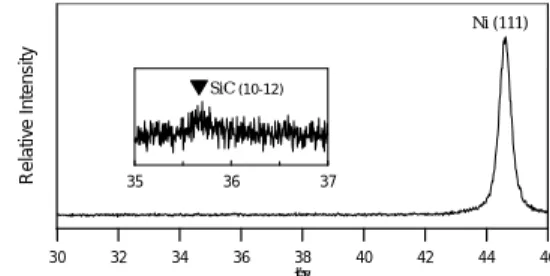
The XRD result of a Ni/SiC composite layer is shown in Fig. 6. The diffraction intensity of the SiC is very weak relatively to the nickel peak (111). The enclosed spectrum in Fig. 6 shows the peak of (1012)6H belonging to 6H-SiC phase.
Fig. 3 Variation of zeta potential of SiC sus-pensions with different concentration of NiCl2 as electrolyte.
Fig. 4 The zeta potential of dilute SiC suspensions with Ni(SO3NH2)2 as electrolyte.
Fig. 5 The streaming current of SiC or SCD at various concentration of nickel sulfamate.
Fig. 6 X-Ray diffraction patterns of an electro-plating Ni layer with ultra-fine SiC particles
1 2 3 4 5 6 7 8 9 10 11 12 13 pH -70.0 -60.0 -50.0 -40.0 -30.0 -20.0 -10.0 0.0 10.0 20.0 30.0 40.0 50.0 60.0 Z e ta -p o te n ti a l (m V ) 1 X 10⁻⁶M 1 X 10⁻³M 0.023 M of NiCl2 0 M (a) 2.0 3.0 4.0 5.0 6.0 7.0 8.0 pH -20.00 -10.00 0.00 10.00 20.00 30.00 40.00 Z e ta P o te n ti a l (m V ) 0.01N Ni(SO3NH2)2 0.1 N Ni(SO3NH2)2 0.01N Ni(SO3NH2)2+ Co agent 0.1 N Ni(SO3NH2)2+ Co agent 1E-5 1E-4 0.001 0.01 0.1 1 10
Concentration of nickel sulfamate (M) -1.00 -0.80 -0.60 -0.40 -0.20 0.00 0.20 0.40 0.60 0.80 1.00 S C R e a d in g (m A )
Nickel sulfamate base plating solution (pH=4) Plating solution without any SiC particle (PTFE)
30 32 34 36 38 40 42 44 46 2θ R e la ti v e In te n s it y Ni (111) SiC 35 36 37 (10-12)
The cross-sections of polished SiC/Ni composite coating is shown in Fig. 7. The composite layer is electroplated in the solution with ultra-fine SiC. Many fine SiC particles forms concentrated domains (SCD) in the Ni matrix and disperses uniformly.
The TEM micrographs of the cross section of SiC composite layers are shown in Fig 5 The ultra-fine SiC particles dispersed uniformly in the locally Ni matrix. The grain size of the metal matrix is uniaxial shape and some twins exist in the Ni matrix. The diffraction pattern of the region is a ring pattern, which imply that the grain size of the Ni is fine and no any prefer orientation is found. The mean grain size of Ni is about 150 nm. The grain size is significant smaller than the layer of free particle.
3.4 Har dness and tr ibology proper ties of the composite coatings
Fig. 9 shows that the friction coefficient of a Ni/SiC composite and Ni coatings. The average value of 0.3 is higher than that (0.15) of a pure nickel. It suggested that the wear mechanisms of these coatings are different, adhesive type of Ni or abrasive type of Ni/SiC composite layer to a tempered steel (NSOH/B01).
The wear results of the composite layer and pure nickel are reported in Fig. 10. The wear rate of the composite layer without heat-treatment is in an average of 6x10⁻⁹ cm3/N·m, apparently better than the pure Ni. However, after 400°C heat treatment for 24 hr, the wear rate of a treated SiC/Ni layer is in the same range of wear resistance, but the wear rate of the treated pure Ni increases about 50 times.
The hardness variation of pure Ni and Ni/SiC composite is shown in Fig. 11. The hardness of a pure nickel increases from 270 Hv to 500 Hv if consisted of nano-SiC particles in the plating solution. When a serious of heat treated temperatures is applied for 1 hr, the hardness of pure nickel decreases starting from 200°C. But the hardness of the Ni/SiC composite resists to change until 500°C.
At room temperature, the improvement of the hardness from 270 Hv to 500 Hv can be due to the dispersive strengthening effect offered by the nano-size particles. But the increment of the friction coefficient of the layer reduces the hardening effect. So the wear resistance of untreated SiC/Ni layer no significant improved. When the deposited layer was treated at higher temperatures (200°C << 500°C), the addition of the SiC particles is able to inhibit the grain growth of nickel grains. Therefore, the Ni/SiC composite layer keeps the same wear resistant as it has at room temperature, and significant improves hardness and heat resistance than a pure Ni, if both samples are treated at 200°C ~ 500°C.
Fig. 7 SEM micrographs of the cross sections of Ultra-fine SiC/Ni composite layer.
(a)
(b)
Fig. 8 TEM micrographs of the SiC/Ni composite coating. (a) BF image, (b) DF image and SADP of
previous region
Fig. 9 The friction coefficient ( µ) of pure Ni and Ni/SiC composite worn against tempered.
0 1000 2000 3000 4000 Revolutions 0.10 0.15 0.20 0.25 0.30 0.35 0.40 F ri c ti o n C o e ff ic ie n t ( µ ) Ni/SiC composite Pure Ni 0 500 1000 1500 2000 Distance (m)
5
4. Conclusion
The IEP of the SiC measured from electrophoresis is pH 2.6, but ICP at pH 3.0 for streaming current. In the aqueous solution containing Ni2+ ions, the ultra-fine SiC will adsorb the divalent ions and change the polarity form negative to positive in the range of pH 4~8. This phenomenon is found both in the nickel chloride and nickel sulfamate suspensions. Ni(OH)2 hydrate is precipitated and the surface potential of the SiC reduced when the concentration of hydroxyl ion increases.
The SiC particle suspended in the conventional Ni electro-plating solution, the electrokinetic charge analysis found that the surface charge of the SiC or PTFE can adsorbe the Ni2+ ions and obtain a positive charged surface. The microstructural observation reveals that the ultra-fine SiC particles may form SiC concentrated domains dispersed in the nickel matrix. But the SiC disperses uniformly in local Ni matrix. The grain growth of the matrix inhibits by the SiC inclusions in the size of 150 nm
and many twins exist in the crystal.
The friction coefficient of SiC/Ni composite coating is higher than that of pure Ni. But the wear rate of SiC/Ni composite coatings is significant better than a pure Ni after 400°C heat treatment for 24 hr. The hardness of the Ni coating is increased form 270 Hv to 550 Hv by the addition of SiC and the thermal resistance of Ni layer can be improved to 500°C.
Acknowledgment
The authors gratefully thank the sponsor, Wah Lee Ind. Co. and National Science Council (NSC89-2216-E-002-016) for the financial support, and also thank the engineers in the R & D division, China Steel Co., for their assistance of electroplating.
References:
1. T. Sakka, D. D. Bidinger and I. A. Aksay, J. Am. Ceram. Soc., 78 [2] 479-86 (1995)
2. R. J. Hunter, Foundations of colloid science, Vol. 1, Oxford university press, (1989)
3. P. K. Whitman and D. L. Feke, J. Am. Ceram. Soc., 71 [12],1086-93, (1988)
4. P. Tartaj, M. Reece, and J. S. Moya, J. Am. Ceram. Soc., 81 [2] 389-94 (1998)
5. L. M. Wang and W. C. Wei, J. Ceram. Soc. Jpn., 103 [5] 434-443 (1995)
6. J. Iskra, Ceramics International, 23, 337-342 (1997) 7. N. Guglielmi, J. Electrochem. Soc.119 [8] 1009-1012
(1972).
8. E. Orowan, discussion in “Symposium on Internal Stresses”, Institute of Metals, Lodon, 145 (1947). 9. K. H. Zum Gahr, Metal Progress, [9] 46 (1979) 10. J. S. Reed, Principles of Ceramics Processing, 2nd
Edition, chap. 10, John Wiley & Sons, (1995) Fig.10 The wear rate of pure Ni and SiC/Ni composite
coating of as-plated or after 24 hrs heat-treated in N2
Fig.11 The hardness change with various heat-treated temperature of Ni/SiC composite and pure nickel layer. 0 1 2 3 4 5 6 7 8 9 Revolution (xk cycles) 1.00E-9 1.00E-8 1.00E-7 1.00E-6 W e a r R a te (c m 3 /N m ) As-plated 24hr-treated SiC/Ni 24 hr-treated As-plated Pure Ni 0 100 200 300 400 500 600 700
Heat Treatment Temperature (°C)
0 100 200 300 400 500 600 H a rd n e s s (H v ) Ni/SiC composite Pure Ni