Three-Dimensional Greedy Anti-Void Routing for
Wireless Sensor Networks
Wen-Jiunn Liu, Student Member, IEEE, and Kai-Ten Feng, Member, IEEE
Abstract—Due to the low-cost design nature of greedy-based
routing algorithms, it is considered feasible to adopt this type of schemes within the three-dimensional (3D) wireless sensor networks. In the existing research work, the unreachability prob-lem (i.e., the so-called void probprob-lem) resulting from the greedy routing algorithms has not been fully resolved, especially under the 3D environment. In this letter, a three-dimensional greedy anti-void routing (3D-GAR) protocol is proposed to solve the 3D void problem by exploiting the boundary finding technique for the unit ball graph (UBG). The proposed3D rolling-ball UBG boundary traversal (3D-RUT) scheme is employed to guarantee the delivery of packets from the source to the destination node. The correctness proofs, protocol implementation, and performance evaluation for the proposed3D-GAR protocol are also given in this letter.
Index Terms—Greedy routing, void problem, unit ball graph,
three-dimensional, wireless sensor network.
I. INTRODUCTION
I
N recent years, three-dimensional (3D) routing has gained attention in the wireless sensor networks (WSNs). For example, the applications for underwater sensor networks have become more popular in the field of oceanographic engi-neering, including data collection, water monitoring, pollution control, and ocean surveillance. Previous work on the routing protocols for the 3D WSNs can be found in [1]. Due to the limited available resources, efficient design of localized routing protocols becomes a crucial subject within the 3D WSNs. How to guarantee delivery of packets is considered an important issue for the localized routing algorithms. The well-known greedy forwarding (GF) protocol [2] is proposed as a superior scheme with its low routing overheads and the adaptability to the3D-routing environment. However, the unreachability problem (i.e., the so-called void problem [3]) occurring within the GF algorithm will fail to guarantee the delivery of data packets. In order to alleviate the void problem, the 3D-ABLAR protocol [4] employs the heuristic next-hop selection techniques that forward packets to additional two neighbor nodes located in separated regions so as to gain more chance to escape from the void. The projection from two-dimensional (2D) face routing to 3D space is also proposed in [5] as another technique to deal with the void problem.Manuscript received February 12, 2009; revised June 28, 2009; accepted August 31, 2009. The associate editor coordinating the review of this letter and approving it for publication was F.-N. Pavlidou.
The authors are with the Department of Communication Engineer-ing, National Chiao Tung University, Hsinchu, Taiwan (e-mail: [email protected]; [email protected]).
This work was in part funded by the Aiming for the Top University and Elite Research Center Development Plan, NSC 96-2221-E-009-016, the MediaTek research center at National Chiao Tung University, and the Universal Scientific Industrial (USI) Co., Taiwan.
Digital Object Identifier 10.1109/TWC.2009.12.090220
SV N5 N3 N4 SX SY SV R/2 X Y Z NS R/2 N7 ND N1 N8 R N2 TNV= {NS,NT,N1,N2} NV R/2 NT NX ST N6 NY SV N3 SV R/2 R/ NSS N1 R N2 NVV R/2 NT ST S S N6
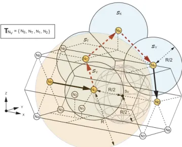
Fig. 1. The example routing path constructed by using the 3D-GAR
algorithm:(𝑁𝑆, 𝑁𝐷) is the transmission pair, and 𝑁𝑉 is the void node.𝑁𝑆, 𝑁𝑇,𝑁1, and𝑁2are within the light-yellow transmission rangeΘ(𝑃𝑁𝑉, 𝑅)
of𝑁𝑉, constructing the one-hop neighbor tableT𝑁𝑉. There exists no SN
inT𝑁𝑉 whose distance to𝑁𝐷is smaller than that of𝑁𝑉 to𝑁𝐷, which
results in the void problem while𝑁𝑆intends to deliver the packets to𝑁𝑉 by
adopting the GF scheme. The3D-GAR algorithm changes its routing strategy
into the3D-RUT scheme, forming the rolling ball 𝑅𝐵𝑁𝑉(s𝑉, 𝑅/2) and the
resulting constrained SP surfaces. In order to clearly visualize the3D diagram,
only the surfaces 𝒮𝑉,𝒮𝑇,𝒮𝑋, and𝒮𝑌 are illustrated, i.e., the light-blue
surfaces. After the surface traversal of𝒮𝑉,𝒮𝑇,𝒮𝑋, and𝒮𝑌 associated with
the corresponding boundary nodes based on the3D-RUT scheme, the GF
scheme can be resumed at𝑁𝑌 whose distance is smaller than that of𝑁𝑉 to
𝑁𝐷. Therefore, the entire path resulting from the3D-GAR protocol can be
obtained as{𝑁𝑆, 𝑁𝑉, 𝑁𝑇, 𝑁𝑋, 𝑁𝑌, 𝑁𝐷}.
However, the void problem resulting from the GF algorithm has not been fully resolved under the 3D environment. In this letter, a 3D greedy anti-void routing (3D-GAR) protocol is proposed to solve the void problem under the unit ball graph (UBG) settings. The associated 3D rolling-ball UBG boundary traversal (3D-RUT) scheme is exploited within the 3D-GAR algorithm with the assurance for packet delivery. Moreover, the proofs of correctness, protocol implementation, and performance evaluation for the proposed algorithms are also described in the end of this letter.
II. NETWORKMODEL ANDPROBLEMSTATEMENT
Considering a set of SNs N = {𝑁𝑖∣ ∀ 𝑖} within a 3D Euclidean spaceℝ3, the locations of the setN are represented
by the set P = {𝑃𝑁𝑖∣ 𝑃𝑁𝑖 = (𝑥𝑁𝑖, 𝑦𝑁𝑖, 𝑧𝑁𝑖), ∀𝑖}, which can be acquired by their own positioning systems. The set of closed balls defining the transmission ranges of N is denoted as Θ = {Θ(𝑃𝑁𝑖, 𝑅) ∣ ∀ 𝑖}, where Θ(𝑃𝑁𝑖, 𝑅) = {x ∣ ∥x − 𝑃𝑁𝑖∥ ≤ 𝑅, ∀ x ∈ ℝ3}. It is noted that 𝑃𝑁𝑖 is the
center of the closed ball with𝑅 denoted as the radius of the transmission range for each𝑁𝑖. Furthermore, a unit ball graph (UBG) is defined as the intersection graph of a group of unit spheres inℝ3. Therefore, the network model for the3D WSNs
can be represented by a3D UBG as 𝐺(P, E) with the edge set E = {𝐸𝑖𝑗∣ 𝐸𝑖𝑗 = (𝑃𝑁𝑖, 𝑃𝑁𝑗), 𝑃𝑁𝑖 ∈ Θ(𝑃𝑁𝑗, 𝑅), ∀ 𝑖 ∕= 𝑗}. The edge 𝐸𝑖𝑗 indicates the unidirectional link from 𝑃𝑁𝑖 to 𝑃𝑁𝑗 whenever the position𝑃𝑁𝑖is within the closed ball region Θ(𝑃𝑁𝑗, 𝑅). Moreover, the one-hop neighbor table for each 𝑁𝑖 is defined asT𝑁𝑖 = {[𝐼𝐷𝑁𝑘, 𝑃𝑁𝑘] ∣ 𝑃𝑁𝑘 ∈ Θ(𝑃𝑁𝑖, 𝑅), ∀ 𝑘 ∕= 𝑖}, where 𝐼𝐷𝑁𝑘represents the designated identification num-ber for 𝑁𝑘. In the greedy forwarding (GF) algorithm, it is assumed that the source node𝑁𝑆 is aware of the location of the destination node𝑁𝐷. If 𝑁𝑆 wants to transmit packets to 𝑁𝐷, it will choose the next hop from its T𝑁𝑆 which (a) has the shortest Euclidean distance to𝑁𝐷 among all the SNs in T𝑁𝑆 and (b) is located closer to𝑁𝐷compared to the distance between𝑁𝑆 and𝑁𝐷. The same procedure will be performed by the intermediate nodes (e.g.,𝑁𝑉 as in Fig. 1) until𝑁𝐷is reached. However, the GF algorithm will be inclined to fail due to the occurrences of voids even though some routing paths exist from𝑁𝑆 to 𝑁𝐷. The void problem is defined as follows:
Problem 1 (Void Problem). The greedy forwarding (GF) al-gorithm is exploited for packet delivery from𝑁𝑆 to𝑁𝐷. The void problem occurs while there exists a void node (𝑁𝑉) in the network such that
{𝑃𝑁𝑘∣ 𝑑(𝑃𝑁𝑘, 𝑃𝑁𝐷) < 𝑑(𝑃𝑁𝑉, 𝑃𝑁𝐷), ∀ 𝑃𝑁𝑘 ∈ T𝑁𝑉} = ∅, (1) where 𝑑(𝑥, 𝑦) represents the Euclidean distance between 𝑥 and𝑦. T𝑁𝑉 is the one-hop neighbor table of𝑁𝑉.
III. PROPOSED3D GREEDYANTI-VOIDROUTING
(3D-GAR) PROTOCOL
The 3D-GAR protocol is a hybrid scheme consisting of both the GF algorithm and the3D rolling-ball UBG boundary traversal (3D-RUT) scheme. The 3D-RUT algorithm is utilized to determine the boundary node set within the networks under the occurrence of void nodes. As the GF algorithm fails due to the void nodes, the3D-RUT scheme can be utilized to escape from the void nodes by traversing the boundary node set and finally restart the GF forwarding process again. The packet delivery from𝑁𝑆 to𝑁𝐷 can therefore be guaranteed. A. 3D Rolling-ball UBG Boundary Traversal (3D-RUT) Scheme
The 3D-RUT scheme is adopted to solve the boundary finding problem and acquire the so-called boundary node set (which will be defined later in this subsection) within the networks. The definition of boundary and the problem statement are described as follows.
Definition 1 (Boundary). A boundary is defined as a closed surface that partitions the set of SNsN into two disconnected groups.
Problem 2 (Boundary Finding Problem). Given a UBG 𝐺(P, E) and the one-hop neighbor tables T = {T𝑁𝑖∣ ∀ 𝑁𝑖∈
NB S (a) (b) N6 N4 N2 Nj X Y Z NA Ni N3 N5 N1 i Si S1 Sj S2 S3 S5 S6 S4 S j R/2 R
Outer Surface of Hollow 3D Solid Object
N2 Nj NA N1 Ni S6 F= {Si,Sj,S1,S2,S3,S4,S5, } H
Surface Visit Order
Si (1) (2) (3) , , SjS1S2,S3,S4 S6 ,S5
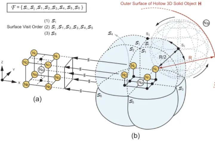
Fig. 2. The3D rolling-ball UBG boundary traversal (3D-RUT) scheme: Fig.
2(a), the 3D scenograph of the internal part of Fig. 2(b), represents a cube
with a node 𝑁𝐴 at the center and{𝑁𝑖, 𝑁𝑗, 𝑁1, 𝑁2, 𝑁3, 𝑁4, 𝑁5, 𝑁6} at
the eight corners. Given s𝑖 and𝑁𝑖, the 3D-RUT scheme freely rotates the
rolling ball𝑅𝐵𝑁𝑖(s𝑖, 𝑅/2) hinged at 𝑁𝑖and constructs the eight constrained
SP surfaces 𝒮𝑖,𝒮𝑗,𝒮1,𝒮2,𝒮3,𝒮4,𝒮5, and𝒮6, which can be aggregated
and considered as a boundary (i.e., the light-blue closed surface). The set
B = {𝑁𝑖, 𝑁𝑗, 𝑁1, 𝑁2, 𝑁3, 𝑁4, 𝑁5, 𝑁6} is established as a boundary node
set by adopting the3D-RUT scheme.
N}, how can a boundary be obtained by exploiting the distributed computing techniques?
The concept of adopting the 3D-RUT scheme to resolve the boundary finding problem is briefly described as follows. Considering the cube formed by nine nodes as the vertices in Fig. 2(a), a3D ball hinged at one of the vertex node with a radius of 𝑅/2 can be formed and freely rotated. It is noticed that the rolling ball is defined without any network node inside the ball. As in Fig. 2(b), it can be observed that the center points of the rotated balls can draw the closed blue surface, which is viewed as the boundary since this closed surface partitions the network into two disconnected parts, i.e., the nine nodes on the cube vertices as one network segment and node𝑁𝐵as the other part. This type of rotated balls and their corresponding center points are formally defined as the rolling balls and the starting points (SPs) as follows:
Definition 2 (Rolling Ball). Given 𝑁𝑖 ∈ N, a rolling ball 𝑅𝐵𝑁𝑖(s𝑖, 𝑅/2) is defined as follows: (a) a closed ball hinged at𝑃𝑁𝑖 with its center point at s𝑖 ∈ ℝ3 and the radius equal to𝑅/2; and (b) there exists no node 𝑁𝑘 ∈ N located inside the rolling ball.
Definition 3 (Starting Point). The starting point (SP) of𝑁𝑖 within the3D-RUT scheme is defined as the center point s𝑖∈ ℝ3 of𝑅𝐵
𝑁𝑖(s𝑖, 𝑅/2).
The detailed mechanism of the proposed3D-RUT scheme is explained as follows. By means of computational geometry, each node 𝑁𝑖 can verify if it has an SP or not by utilizing its one-hop neighbor table T𝑁𝑖 since the rolling ball of 𝑁𝑖 is always bounded by 𝑁𝑖’s transmission range. Given s𝑖 as an SP associated with its rolling ball 𝑅𝐵𝑁𝑖(s𝑖, 𝑅/2) hinged at 𝑁𝑖, the rolling ball can freely rotate in all directions (i.e., 360∘) within the3D space as shown in Fig. 2. Based on the rotation of the rolling ball𝑅𝐵𝑁𝑖(s𝑖, 𝑅/2), an SP surface will be generated with the accumulation of the corresponding SPs.
However, according to Definition 2 that there should not exist any SN located inside the rolling ball, the resulting SP surface will become a constrained SP surface𝒮𝑖since the rolling ball can be stuck by some of the SNs in the network. These SNs are denoted as the surface-adjacent nodes of𝑁𝑖, i.e.,𝑁𝑗,𝑁1,
𝑁2, 𝑁3, 𝑁4, and 𝑁5 as shown in Fig. 2. It is noticed that
these surface-adjacent nodes can be served as the next hopping nodes of𝑁𝑖.
Subsequently,𝑁𝑖 will inform these surface-adjacent nodes to continue the3D-RUT scheme by sending control packets that contain the information of their corresponding SPs in order to construct other constrained SP surfaces. For exam-ple, as shown in Fig. 2, the surface-adjacent node 𝑁𝑗 can continue the 3D-RUT scheme by adopting the rolling ball 𝑅𝐵𝑁𝑗(s𝑗, 𝑅/2) along with the newly assigned SP s𝑗, which is located on the border of the constrained SP surface 𝒮𝑖. Based on the same rotating procedure that is implemented by the rolling ball𝑅𝐵𝑁𝑗(s𝑗, 𝑅/2) hinged at 𝑁𝑗, the constrained SP surface𝒮𝑗 can therefore be constructed. Repeatedly,𝑁𝑗’s surface-adjacent nodes will be notified to continue the 3D-RUT scheme. As a result, all the constrained SP surfaces are established and identified as𝒮𝑖, 𝒮𝑗, 𝒮1, 𝒮2,𝒮3,𝒮4, 𝒮5, and
𝒮6, which can be aggregated into a closed surface ℱ, i.e.,
the light-blue surface as in Fig. 2. For reader’s clearness, the surface visit order starting from𝒮𝑖 is also summarized as in Fig. 2. This closed surfaceℱ is regarded as a boundary that is denoted in Definition 1; while the corresponding SNs that define the closed surface are represented as the elements in the boundary node set as follows:
Definition 4 (Boundary Node Set). The boundary node set B ⊆ N is defined as the SNs that construct the boundary based on the3D-RUT scheme.
Consequently, according to those eight constrained SP sur-faces shown in Fig. 2, the boundary node set for this example can be obtained as B = {𝑁𝑖, 𝑁𝑗, 𝑁1, 𝑁2, 𝑁3, 𝑁4, 𝑁5, 𝑁6}.
For preventing infinite recursion of the algorithm, each SN inB will only implement the 3D-RUT scheme once for the same boundary. Moreover, the reverse path of each SN inB to the original SN 𝑁𝑖 can be obtained by referring to the previously visited constrained SP surfaces. For example, the surface traversing order can be obtained from 𝒮𝑖, via 𝒮𝑗, to 𝒮6 as in Fig. 2. Therefore,𝑁6 can construct the reverse path
𝑁6 → 𝑁𝑗 → 𝑁𝑖 in order to communicate with the original node𝑁𝑖.
B. Detailed Descriptions of Proposed3D-GAR Protocol As shown in Fig. 1, the packets are intended to be delivered from𝑁𝑆 to𝑁𝐷.𝑁𝑆will select𝑁𝑉 as the next hop by adopt-ing the GF algorithm. However, the void problem prohibits 𝑁𝑉 to continue utilizing the same GF algorithm for packet forwarding. The 3D-RUT scheme is therefore employed by assigning an SP (i.e., s𝑉) associated with the rolling ball 𝑅𝐵𝑁𝑉(s𝑉, 𝑅/2) hinged at 𝑁𝑉. It is noticed that there should always exist an SP for each void node (𝑁𝑉), which can be proved in Property 1 as follows:
Property 1. There always exists an SP s𝑉 for a void node 𝑁𝑉 w.r.t. the destination node𝑁𝐷.
Proof: It is assumed that 𝛾 is denoted as the Euclidean distance between 𝑁𝑉 and 𝑁𝐷. Based on the definition of a void node, there will not be any SN located inside the intersection area Υ of the two closed balls Θ(𝑃𝑁𝑉, 𝑅) and Θ(𝑃𝑁𝐷, 𝛾). Considering a point s𝑉 located on the connecting line between 𝑁𝑉 and 𝑁𝐷 with 𝑅/2 away from 𝑁𝑉, the closed ball Θ(s𝑉, 𝑅/2) will be situated inside the node-free intersection region Υ. According to Definitions 2 and 3, s𝑉 will be an SP for𝑁𝑉. It completes the proof.
Based on Property 1, s𝑉 can be chosen to locate on the connecting line between 𝑁𝑉 and 𝑁𝐷 with𝑅/2 away from 𝑁𝑉 as illustrated in Fig. 1. The corresponding constrained SP surfaces can be established by adopting the proposed 3D-RUT scheme. In order to clearly visualize the 3D diagram, only the constrained SP surfaces 𝒮𝑉, 𝒮𝑇, 𝒮𝑋, and 𝒮𝑌 are depicted in Fig. 1 as the light-blue surfaces. Since 𝑁𝑇 is one of the surface-adjacent nodes of𝑁𝑉,𝑁𝑇 will be chosen by 𝑁𝑉 as the next hopping node for continuing the 3D-RUT scheme. Due to the nature of the void node 𝑁𝑉, the distance from 𝑁𝑇 to 𝑁𝐷 should be not smaller than that from𝑁𝑉 to𝑁𝐷, i.e.,𝑑(𝑃𝑁𝑇, 𝑃𝑁𝐷) ≥ 𝑑(𝑃𝑁𝑉, 𝑃𝑁𝐷). Similar procedure will recursively be conducted by nodes 𝑁𝑇, 𝑁𝑋, and others. In the case that there exists a surface-adjacent node 𝑁𝑌 such that 𝑑(𝑃𝑁𝑌, 𝑃𝑁𝐷) < 𝑑(𝑃𝑁𝑉, 𝑃𝑁𝐷), 𝑁𝑌 will inform 𝑁𝑉 regarding the escape route from the void node based on the reverse path identified by the3D-RUT scheme, e.g., 𝑁𝑉 → 𝑁𝑇 → 𝑁𝑋 → 𝑁𝑌 as illustrated in Fig. 1. Consequently, the GF algorithm will be resumed at 𝑁𝑌, and the route from 𝑁𝑆 to 𝑁𝐷 can therefore be constructed for packet delivery, e.g.,{𝑁𝑆, 𝑁𝑉, 𝑁𝑇, 𝑁𝑋, 𝑁𝑌, 𝑁𝐷} as in Fig. 1. Moreover, if there does not exist a node 𝑁𝑌 such that 𝑑(𝑃𝑁𝑌, 𝑃𝑁𝐷) < 𝑑(𝑃𝑁𝑉, 𝑃𝑁𝐷), the 3D-RUT scheme will be terminated after completing the traversal of the boundary node set, e.g., the yellow nodes as depicted in Fig. 2. The result indicates that there is no routing path between𝑁𝑆 and𝑁𝐷. C. Proof of Correctness
Lemma 1. A closed surface is established by all the SPs resulting from the3D-RUT scheme.
Proof: The relationship that "all the SPs within the 3D-RUT scheme form the surface of the resulting3D solid object by overlapping the closed ballsΘ(𝑃𝑁𝑖, 𝑅/2) for all 𝑁𝑖∈ N" is proven first. Based on Definitions 2 and 3, the set of SPs can be obtained asS = R1∩R2= {s𝑖∣ ∥s𝑖−𝑃𝑁𝑖∥ = 𝑅/2, ∃𝑁𝑖∈ N, s𝑖 ∈ ℝ3} ∩ {s𝑗∣ ∥s𝑗− 𝑃𝑁𝑗∥ ≥ 𝑅/2, ∀𝑁𝑗 ∈ N, s𝑗 ∈ ℝ3} by adopting the (a) and (b) rules within Definition 2. On the other hand, the surface of the resulting 3D solid object from the overlapped closed ballsΘ(𝑃𝑁𝑖, 𝑅/2) for all 𝑁𝑖∈ N can be denoted as Ω = Q1 − Q2 = ∪𝑁𝑖∈N𝐾(𝑃𝑁𝑖, 𝑅/2) − ∪
𝑁𝑖∈NΘ(𝑃𝑁𝑖, 𝑅/2), where 𝐾(𝑃𝑁𝑖, 𝑅/2) and Θ(𝑃𝑁𝑖, 𝑅/2) represent the surface of a closed ball and the open ball centered at𝑃𝑁𝑖with a radius of𝑅/2 respectively. It is obvious to notice that R1 = Q1 and R2 = Q′2, which result in S = Ω and
manifest the relationship in the beginning of this paragraph. Continuing the proof of this lemma, the surface of a3D solid object will apparently result in a closed surface. Therefore, a closed surface is constructed by the combination of the SPs
resulting from the3D-RUT scheme, e.g., the light-blue surface as in Fig. 2. It completes the proof of this lemma.
Theorem 1. The boundary finding problem (Problem 2) is resolved by the3D-RUT scheme.
Proof: Based on Lemma 1, a closed surface (denoted as ℱ) is constructed from the 3D-RUT scheme by rotating the rolling balls 𝑅𝐵𝑁𝑖(s𝑖, 𝑅/2) hinged at 𝑃𝑁𝑖 for all 𝑁𝑖 ∈ N. For example, as shown in Fig. 2,ℱ = {𝒮𝑖,𝒮𝑗,𝒮1,𝒮2,𝒮3,𝒮4,
𝒮5, 𝒮6} is represented as the light-blue surface, and all SNs
at which the corresponding rolling balls have been hinged are denoted by the set U = {𝑁𝑖, 𝑁𝑗, 𝑁1, 𝑁2, 𝑁3, 𝑁4, 𝑁5, 𝑁6}.
Moreover, a hollow3D solid object H is defined by the space that are traversed by those rolling balls, where the thickness of the objectH will be equal to 𝑅 since it is equivalent to the diameter of the rolling balls. The partial outer surface of H is illustrated as in Fig. 2(b). It is noticed that the closed surfaceℱ will become a layer of H situated at distance 𝑅/2 inward from the outer surface ofH.
Based on Definition 2, there is no SN located inside the rolling ball which consequently results in the case that there will be no SN within the3D solid object H. It can be observed that two disconnected regions can be derived as the inner and the outer spaces that are separated byH since, for all 𝑁𝐴∈ N in the inner space, the smallest distance from 𝑁𝐴 to𝑁𝐵 located in the outer space is greater than the SN’s transmission range𝑅. Consequently, the closed surface ℱ situated within H can be considered as a boundary defined in Definition 1 that partitionsN into two disconnected groups. As the example in Fig. 2(b), the set of nodesU and node 𝑁𝐴are located in the inner space; while node𝑁𝐵is situated in the outer space. The setU can therefore be obtained as the boundary node set B based on Definition 4. It completes the proof.
Theorem 2. The void problem (Problem 1) is solved by the 3D-GAR protocol with guaranteed packet delivery.
Proof: With the existence of the void problem occurring at any void node𝑁𝑉, the3D-RUT scheme is utilized by initi-ating an SP (s𝑉) with the rolling ball𝑅𝐵𝑁𝑉(s𝑉, 𝑅/2) hinged at𝑁𝑉. The3D-RUT scheme within the 3D-GAR protocol will conduct boundary traversal via the associated boundary node setB under the condition that 𝑑(𝑃𝑁𝑖, 𝑃𝑁𝐷) ≥ 𝑑(𝑃𝑁𝑉, 𝑃𝑁𝐷) for all𝑁𝑖∈ B. If the boundary within the underlying network is completely traveled based on Theorem 1, it indicates that the SNs inside the boundary (e.g., 𝑁𝑉) are not capable of communicating with those located outside of the boundary (e.g.,𝑁𝐷). The result shows that there does not exist a route from the void node (𝑁𝑉) to the destination node (𝑁𝐷), i.e., the existence of network partition. On the other hand, if there exists a node 𝑁𝑌 such that 𝑑(𝑃𝑁𝑌, 𝑃𝑁𝐷) < 𝑑(𝑃𝑁𝑉, 𝑃𝑁𝐷) (e.g., in Fig. 1), the GF algorithm will be adopted within the 3D-GAR protocol to conduct data delivery toward the destination node𝑁𝐷. Therefore, the3D-GAR protocol solves the void problem with guaranteed packet delivery, which completes the proof.
IV. PROTOCOLIMPLEMENTATION
After describing the design concept of the proposed 3D-GAR scheme, the implementation issues of the proposed
protocol consisting of both the GF and the3D-RUT algorithms are explained in this section. The GF scheme is considered a sequential table-lookup algorithm that only requires the implementation of the one-hop neighbor table. Therefore, both the time and space complexities are𝑂(𝑚), where 𝑚 represents the number of neighbors specified in the one-hop neighbor table. If the void problem occurs, the 3D-RUT scheme is utilized to forward packets to the nodes in the boundary node setB as defined in Definition 4. Since a node 𝑁𝑖’s neighbors in the boundary node set can construct rolling balls with𝑁𝑖, the original mechanism of forwarding packets to the nodes in B can therefore be transformed into a simple forwarding rule. In other words, node 𝑁𝑖 which currently conducts the 3D-RUT scheme simply forwards packets to those neighbors that can form a rolling ball with 𝑁𝑖, where these neighbors can be obtained by the following method. For each pair of nodes (𝑁𝑗,𝑁𝑘) in the one-hop neighbor table of𝑁𝑖, if a node-free-inside circumscribed ball hinged at𝑁𝑖 with a radius of 𝑅/2 can be established with both nodes𝑁𝑗and𝑁𝑘 on the surface of the ball, the definition of the rolling ball (i.e., Definition 2) will be satisfied since the two conditions are satisfied as follows: (a) node𝑁𝑖is located on the surface of the ball; and (b) there does not exist any neighbor node situated inside the ball. As a result, both𝑁𝑗 and𝑁𝑘 are considered as the next hopping nodes of𝑁𝑖for packet forwarding. It is noted that the time complexity of this process is 𝑂(𝑚3) since three nested
loops to go through the one-hop neighbor table are required to conduct this procedure; while the space complexity is still 𝑂(𝑚) since only the construction of the neighbor table is required. Finally, by considering both the GF and the3D-RUT schemes, the time and space complexities of the 3D-GAR protocol can be acquired as 𝑂(𝑚3) and 𝑂(𝑚) respectively,
where𝑚 is the number of neighbors specified in the one-hop neighbor table.
V. PERFORMANCEEVALUATION
The performance of the proposed 3D-GAR algorithm is evaluated and compared with other three protocols via simula-tions, including the3D-ABLAR, the network flooding, and the reference GF algorithms. The simulation settings are explained as follows. A number of 1000 SNs are randomly deployed in the Euclidean 3D box ranging from (0, 0, 0) to (1000, 800, 1200) in the unit of meters. The transmission range of a node is250 m. A pair of source and destination nodes are respectively located at (0, 400, 600) and (1000, 400, 600). The source node is with the data transmitting rate of 16 Kbps and data packet size of 512 bytes. There also exists a void block with length 400 m, width 800 m, and variable heights. This void block is randomly placed in the network in order to simulate the occurrence of void problems. In other words, there are SNs around the peripheral of the void block; while none of the nodes is situated inside the void block. Three performance metrics are utilized in the simulations for performance comparison as follows: (a) packet arrival rate: the ratio of the number of received data packets to the number of total data packets sent by the source; (b) path length: the average path length of successful routing in the unit of hop count; and (c) routing overhead: the average number of transmitted bytes per second for a network node.
400 450 500 550 600 650 700 750 800 60 65 70 75 80 85 90 95 100 Void Height (m)
Packet Arrival Rate (%)
3D−GAR 3D−ABLAR FLOODING GF
(a) Packet arrival rate (%)
400 450 500 550 600 650 700 750 800 5 5.5 6 6.5 7 7.5 Void Height (m) Path Length 3D−GAR 3D−ABLAR FLOODING GF
(b) Path length for successful transmission
400 450 500 550 600 650 700 750 800 101
102
103
Void Height (m)
Routing Overhead (byte/sec)
3D−GAR 3D−ABLAR FLOODING GF
(c) Routing overhead (byte/sec)
Fig. 3. Performance evaluation for the proposed3D-GAR protocol.
Fig. 3(a) shows the packet arrival rate performance versus the void height. Due to the property of guaranteed delivery, both the3D-GAR and network flooding algorithms will result in the delivery rate of 100%. The 3D-ABLAR and the GF protocols incur less delivery rate with regard to the increase of void height since the void problem occurs frequently when the void height becomes large. The3D-ABLAR protocol has higher delivery rate than the GF algorithm owing to the reason that the GF scheme drops packet directly as the void problem occurs. Fig. 3(b) illustrates the performance of average path length for successful routing versus the void height. The net-work flooding algorithm results in the lowest value under small void heights since it can always find the shortest path between the source and the destination. However, as the void height becomes large, both the 3D-ABLAR and GF schemes will incur relatively smaller value of path length. The major reason is due to the100% of packet delivery rate from the network flooding algorithm, which requires additional packet rerouting as the void problem becomes severe. The same reason can be applied to the curve obtained from the3D-GAR protocol, which possesses a slightly longer routing path than the other protocols, e.g., around 1.8 additional hops under the void height of 800 m. Nevertheless, even with the slightly larger path length, the 3D-GAR protocol can result in guaranteed delivery rate as shown in Fig. 3(a), which outperforms both the3D-ABLAR and GF schemes with lowered packet delivery rate.
Fig. 3(c) shows the performance of routing overhead versus the void height. It can be observed that both the3D-ABLAR and GF schemes result in comparatively low overhead since most of the packets are dropped due to the void problem. In order to guarantee delivery and to find the shortest path, the network flooding algorithm generates a large number of
packets in comparison with other protocols, which contributes to a significant amount of routing overhead as shown in Fig. 3(c). Comparing with the network flooding algorithm, the 3D-GAR protocol can achieve guaranteed packet delivery with a comparably smaller number of packets since the 3D-GAR scheme limits the packet rerouting only to nodes that are in the boundary node set. The merits of the proposed3D-GAR protocol can therefore be observed, which achieves guaranteed packet delivery with reasonable routing overhead.
VI. CONCLUSION
In this letter, a three-dimensional greedy anti-void routing (3D-GAR) protocol is proposed to completely resolve the void problem incurred by the conventional greedy forward-ing algorithm under the 3D environment. The 3D rolling-ball UBG boundary traversal (3D-RUT) scheme is adopted within the 3D-GAR protocol to solve the boundary finding problem, which results in the guarantee of packet delivery. In the end, the correctness proofs, protocol implementation, and performance evaluation of the proposed algorithms are properly provided.
REFERENCES
[1] M. C. Domingo and R. Prior, “Energy analysis of routing protocols for underwater wireless sensor networks," Computer Commun., vol. 31, no. 6, pp. 1227-1238, Apr. 2008.
[2] G. G. Finn, “Routing and addressing problems in large metropolitan-scale internetworks," Inf. Sci. Inst. (ISI), Tech. Rep. ISI/RR-87-180, Mar. 1987. [3] B. Karp and H. T. Kung, “GPSR: greedy perimeter stateless routing for wireless networks," in Proc. ACM/IEEE Int. Conf. Mobile Computing Networking, Aug. 2000, pp. 243-254.
[4] A. E. Abdallah, T. Fevens, and J. Opatrny, “Hybrid position-based 3D routing algorithms with partial flooding," in Proc. Canadian Conf. Electrical Computer Engineering, May 2006, pp. 227-230.
[5] G. Kao, T. Fevens, and J. Opatrny, “3-D localized position-based routing with nearly certain delivery in mobile ad hoc networks," in Proc. Int. Symp. Wireless Pervasive Computing, Feb. 2007, pp. 344-349.