Scattering analysis of the indium-tin-oxide (ITO)
nanowhiskers on ITO film substrate for thin film solar cell
Hsiao-Wei Liu
a, Chia-Hua Chang
a, Chien-chung Lin
band Peichen Yu
a*a
Department of Photonics and Institute of Electro-Optical Engineering, National Chiao Tung
University, Hsinchu 30010, Taiwan
b
Institute of Photonic System, National Chiao Tung University, Tainan 711, Taiwan, R. O. C.
E-Mail:
[email protected]
ABSTRACT
Light trapping techniques such as textured interfaces and highly reflective back contacts are important to thin-film solar cells. Scattering at rough interfaces inside a solar cell leads to enhanced absorption due to an increased optical path length in the active layers, which is generally characterized by a haze ratio. In this work, we demonstrate the measured haze characteristics of indium tin oxide nano-whiskers deposited on an ITO-coated glass substrate. A theoretical model based on a modified Mie theory is also employed to analyze the scattering effects of nano-whiskers. Instead of spherical model, a cylindrical condition is imposed to better fit the shapes of the whiskers. The calculated haze-ratio of an ITO whisker layer matches the measurement closely.
Keywords: ITO whisker, haze ratio, Mie theory
1. INTRODUCTION
The power conversion efficiency (PCE) of thin film solar cell depends on the effective light absorption, which can improved by light trapping mechanism in broadband wavelength range [1]. The high scattering efficiency of incident light will increase the optical path and enhance the light absorption in thin film solar cell. Conventionally, the transmission scattering is designed at the top surface, which can scatter the incident light and distribute the light field in the solar active layer. In experiment, the capability of scattering could be defined by the haze ratio where:
⎟ ⎠ ⎞ ⎜ ⎝ ⎛ − × = total specular T T Haze 100% 1 (1)
With this definition, the scattering capability of the solar cell can be easily evaluated by this haze ratio of the surface. In the past, micro-scale surface structures were applied to raise the scattering capability. However, the micro structure would increase the haze-ratio but reduce the total transmittance due to the surface reflection, which in turn decreases the photons absorption. On the other hand, the nano-scale structure for scattering layer has shown superior properties for both antireflection and scattering efficiency [2]. In our research, the scattering characteristics of the nano-scale whisker layer on transparent substrate were investigated. The whiskers were fabricated by electron beam evaporation system. We demonstrate the measured haze characteristics of novel indium tin oxide (ITO) nano-whiskers deposited on an ITO-coated glass substrate. The ITO nano-whiskers for scattering layer have shown superior properties for both antireflection and scattering efficiency. Moreover, as ITO is a widely used transparent conductive oxide material and the growth technique involves only deposition in low temperature, it is very appealing to employ nano-whiskers in thin-film solar cells as light trapping textures.
Then, we attempted to construct an equivalent sphere model to fit the haze ratio and analysis characteristics of ITO whisker. With a correct model, we can decide the scattering efficiency by designing the structure and shape size. The scattering effect will be discussed in the later with the model fitting results.
Physics, Simulation, and Photonic Engineering of Photovoltaic Devices,
Edited by Alexandre Freundlich, Jean-Francois F. Guillemoles, Proc. of SPIE Vol. 8256, 82560A © 2012 SPIE · CCC code: 0277-786X/12/$18 · doi: 10.1117/12.908854
Proc. of SPIE Vol. 8256 82560A-1
The nano-wh attached to a equipped with target source beginning of a nitrogen flo 260ºC and ~1 Fig.1 22.2 Figure 1 show times: (a) 22. diameter 40~ coating glass In these (VLS) [3] pr three steps, a thin film with phase at whic composition l The second st precipitates. T the liquid-sol branch grows branch is com . Fi hiskers were de holder, which h seven holde contained 5 w the evaporatio ow rate at 1 sc 10-4 Torr with 1 The scanning minutes (b) 16 ws the scannin 2 minutes, (b) ~50 nm and s substrate. An structures, th rocess, which as shown in fi h a liquid pha ch In2O3 nuc lowers the me tep is the rod The In2O3 cry
lid system. T s from the In mposed of crys
ig.2 growth mec bra
( )
eposited on an h was tilted at ers which circl wt % SnO2 and
on, the chamb cm to create a a deposition r electron micros .7minutes. ng electron mi ) 16.7 minute everal branch nd a longer dep he growth m is still under igure 2. The f se on the surf clei grow into elting point on growth. The S ystalline cores he concentrat 2O3 trunk by stalline In2O3 (a) chanism of ITO anches, where a
2. EX
n ITO coated a deposition a le around the c d 95 wt % In2 ber pressure w an oxygen-def rate of 0.15 nm (a) scopy (SEM) im icroscopic (SE s, showing the hes on the sidposition time mechanism pre investigation first step is nu face due to ox o the center a n the surface, w Sn-rich liquid grow along th tion of Sn in y breaking thr without any c O whiskers brea a Sn-induced se
XPERIME
glass substrat angle of 70 wi center of the c O3 and waswas first pumpe ficient atmosp m/sec for vari
mage of the ITO
EM) images o e formation o des, where the
results in a hi esumably invo n. In theory, th ucleation, wh xygen deficien and leave the which can abs
phase is supe he lattice dire the core bec rough the Sn-core-shell stru
(b) aks into three m elf-catalyst is th
NTAL
e using electro ith respect to t chamber at a s placed on the ed down to ~ phere. During ious deposition (b) O nanowhiskersof the ITO nan f nano-whiske e nano-whiske gher density o olves a tin-in he growth of ere ITO mole ncy [4]. The li Sn-rich liquid sorb vapor mo ersaturated by ction which fo comes much l -rich liquid su uctures. main step: (a) the he dominant gro on-beam evap the incident v speed of 10 rp e bottom cente 10-6 torr, follo growth, the ch n times. s with different no-whiskers w ers, which inc ers are random of whiskers. nduced self- f ITO nano-wh ecules evapora iquid drops co d phase on th olecules in the the vapor mo forms a trunk t lower than th urface, formin (c) e nucleation, (b owth mechanism poration. The g vapor flux. The pm during dep
er of the cham owed by the in
hamber was s
t deposition tim
with two differ cludes a centra
mly distribute catalytic vapo hiskers can b ated from the onsist of an In he surface [5] e liquid phase olecules, givin to reduce the he liquid surfa ng a whisker b) rod growth, ( m. glass is e system is position. The mber. At the ntroduction of tabilized at me: (a) rent deposition al trunk with a ed on the ITO or-liquid-solid e divided into target form a n-Sn-O ternary . The high Sn continuously ng rise to In2O free energy o ace. Finally, a structure. The c) f n a O d o a y n y. 3 f a e
Proc. of SPIE Vol. 8256 82560A-2
After the nano-structure was grown, we can use the regular Haze measurement setup to evaluate its light-scattering capability. The instrument of U-4100 UV-Visible-NIR Spectrophotometer with a 6-cm diameter integrated sphere was used to characterize the scattered light following the standard ASTM D1003-95
3. MIE THEORY WITH CYLINDRICAL ROD
In the ordinary Mie theory, the shape of scattering particle is spherical. In our case, however, the nanowhisker is nowhere close to spherical shape, and so a better simulation should be obtained by using cylindrical particles in modified Mie theory. There have been some efforts in the past to solve the Mie scattering for particles with non-spherical shapes. Shapes like cylinders, spheroids, etc., are common in nature, such as ice pellets, aerosol pollutants, and even organic tissues. Equivalent volume-to-surface-ratio spheres [10], and Mie approximation [11][12] have been proposed as a possible solution. In this paper, we adapt the Mie approximation as our major method to solve the problem.
In the scattering event of a infinitely-long cylinder shown in Fig. 2, the electromagnetic excitation can strike the long axis of the cylinder with an angle of ζ. In the regular Mie theory, we need to find out the scattering coefficient, and scattering cross section such that we can calculate the attenuation coefficient [12]. Similar treatment needs to be carried out in the cylindrical case. The scattered EM field are written in the series form of the generating functions[12]:
∑
∞ = + = 1 ) ( n n n n n sca aM bN E (2), where an and bn are the scattering coefficients, and Mn and Nn are the generating functions that can satisfy the scalar wave equation in polar coordination [12]. The coefficients can be determined by the Maxwell equations and the expansion of the scattered EM field [12]. And if we assume the electric field is perpendicular to the axis of the cylinder, we can obtain the scattering coefficients like [11]:
2 2 ; n n n n n n n n n n n n n n n n iD V W D C B W b iD V W D B V C a + + = + − = (3) Where
(
)
(
)
(
)
⎪ ⎪ ⎪ ⎪ ⎭ ⎪⎪ ⎪ ⎪ ⎬ ⎫ − = = − = − = − = − = − = ζ η ζ ξ ξ η ξ ξ η η ξ ξ η η ξ η ξ ξ η ξ ξ η ζη ξ η η ξ η ξ ξ η ξ ξ η ζη 2 2 ) 1 ( ' )' 1 ( ' )' 1 ( ) 1 ( ' 2 2 2 ' ' 2 2 2 ) 1 ( cos ; sin ) ( ) ( ) ( ) ( ) ( ) ( ) ( ) ( ; ) 1 )( ( ) ( cos ) ( ) ( ) ( ) ( ; ) 1 )( ( ) ( cos m x x H J H J i W H J H J m V J J n C J J J J m B H J n D n n n n n n n n n n n n n n n n n n n n n (4)and Jn(x), Hn(1)(x) are the Bessel function of the 1st order, and 3rd order, x is 2πa/λ, a is the radius of the cylinder, and m is the complex refractive index of the cylinder material. If the electric field is parallel to the axis of the cylinder, a similar set of formula can also be found[11][12]. The scattering efficiency factor Qi (i=ext, and sca, for extinction and scattering, respectively) can then be calculated through the summation of an and bn [12]:
(
)
⎪ ⎪ ⎭ ⎪ ⎪ ⎬ ⎫ ⎭ ⎬ ⎫ ⎩ ⎨ ⎧ + = ⎥ ⎦ ⎤ ⎢ ⎣ ⎡ + + =∑
∑
∞ − ∞ − 1 0 1 2 2 2 0 2 Re 2 n n I ext n n n I sca b b a n Q a b b a n Q π λ π λ(5)
, where a is the radius of the cylinder and the nI is the real part of the refractive index of the cylinder. We are assuming the electric field is perpendicular to the axis of the cylinder in this case. If the electric field is parallel to the axis, the coefficients an and bn need to be exchanged in their positions in the eq.(5). If the incident light is unpolarized, the
Proc. of SPIE Vol. 8256 82560A-3
efficiency fac factors, the at , where i=ex calculated as under differe capabilities st
ctors are the a ttenuation coe t (extinction) 1-exp(-αsca× ent incident a trongly depen Fig. 4 average of the efficients α can or sca (scatt ×d), and d is t angle (ζ) and nds on the phy Fig. 3. Sche 4. The calculated e coefficients n be solved as N i α = tering), and N the thickness also at differ ysical shapes a ematic diagram o
d haze ratio at (a)
of the two po s[11][12]: 2 a NQiπ
N is the total of the scatteri rent radii of and orientation f a cylindrical ob different inciden olarizations. O
(6) number of th ing medium. F cylinders. Fro n of the cylind
bject with inciden
nt angles, and (b) Once we find o he particles. T Figure 3 show om the plots, ders. nt EM waves. different radius o
out the scatter
The haze ratio ws the calcula
we can see
of cylinders.
ring efficiency
o can then be ated haze ratio the scattering y
e o g
Proc. of SPIE Vol. 8256 82560A-4
4. RESULTS AND DISCUSSION
From the aforementioned theory, we can use MatlabTM and reference to published codes[13] to program the
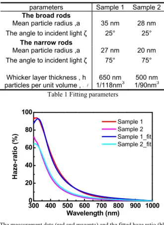
wavelength-dependent haze ratio of nanowhisker and compare the calculation to our measurement. Figure 4 shows our haze fitting of nanowhiskers under various deposition conditions. Two different thickness of ITO nanowhisker films deposited at 260oC
were tested and fitted. To better match the real situation, we put a vertical and horizontal orientation mix of cylinders (4:1) in the calculation. The vertical cylinders are tilted in 25o and the horizontal ones are at 75o, both with respect to
normal direction of the surface. A illustrative diagram of our simulation model is shown in the inset of Fig. 4. The radii of the cylinders are picked as 28 and 35 nm, which are close to what was observed in the TEM picture[7], and real ITO refractive index was used. The effective thickness in the Mie calculation for both cases are 650nm and 500nm, respectively. These numbers are also obtained from the SEM pictures. A close match was found with the parameters we assigned. Little deviations were found at long wavelength range, which might rise from the randomness of the nanowhisker orientation, and the different sizes of whiskers' radii. At short wavelength, the fine branches of whiskers took effect and drove the scattering away from the ideal infinitely-long cylinder condition.
parameters Sample 1 Sample 2
The broad rods
Mean particle radius ,a 35 nm 28 nm The angle to incident light ζ 25° 25°
The narrow rods
Mean particle radius ,a 27 nm 20 nm The angle to incident light ζ 75° 75°
Whicker layer thickness , h 650 nm 500 nm particles per unit volume , N 1/118nm3 1/90nm3
Table 1 Fitting parameters
Fig. 5. The measurement data (red and magenta) and the fitted haze ratio (blue and cyan).
5. RESULTS AND DISCUSSION
A cylinder-based Mie scattering model was used to calculate the haze ratio of nanowhiskers, and we successfully correlate the physical dimensions to our measurement. The result of curve fitting shows that it is a practical and accurate model for visible light range, but some errors induced by difference of ideal and real case exhibit at short and long wavelength. We believe this Mie model can provide a quick estimate of haze ratio and should be helpful for design of next generation of highly diffused nanostructure.
300 400 500 600 700 800 900 1000 0 20 40 60 80 100 Sample 1 Sample 2 Sample 1_fit Sample 2_fit Haze -rat io (% ) Wavelength (nm)
Proc. of SPIE Vol. 8256 82560A-5
ACKNOWLEDGEMENT
The authors are grateful to the National Science Council of the Republic of China, Taiwan, for finan-cially supporting this research. C.C Lin also would like to thank the support of the Contract No. NSC 99-2221-E-009-052-MY3, and NSC 100-3113-E-110-006.
REFERENCE
[1] J. Krc, B. Lipovsek, M. Bokalic, A. Campa, T. Oyama, M. Kambe, T. Matsui, H. Sai, M. Kondo, M. Topic, " Potential of thin-film silicon solar cells by using high haze TCO superstrates, " Thin Solid Film, 518, 3054-3058, (2010).
[2] Naoki Taneda, Kunio Masumo, Mika Kambe, Takuji Oyama and Kazuo Sato, "Highly Textured SnO2 Films For a-Si / μc-Si Tandem Solar Cells," 23rd European Photovoltaic Solar Energy Conference, 1-5 September 2008, Valencia, Spain
[3] U. Kroll, J. Meier, S. Benagli, et al, "Thin Film Silicon PV: From R&D to Large-Area Production Equipment, " Amor-phous, Nano, and Film Si - Plenary Talk, 37th IEEE Photovoltaic Specialist Conference, (2011). [4] J Müller, B Rech, Jiri Springer, M Vanecek, "TCO and Light Trapping in Silicon Thin Film Solar Cells, "
Solar Energy. Vol., 77, pp 917-930, 2004.
[5] D. Domine, F.-J. Haug, C. Battaglia, and C. Ballif, "Modeling of light scattering from micro- and nanotextured surfaces, " J. Appl. Phys. 107, 044504 (2010), DOI:10.1063/1.3295902
[6] Y. J. Lee, D. S. Ruby, D. W. Peters, B. B. McKenzie, J. W. P. Hsu, "ZnO Nanostructures as Efficient Antireflection Layers in Solar Cells," Nano Lett. Vol., 8, pp 1501-1505, 2008.
[7] P. Yu, C. H. Chang, C. H. Chiu, C. S. Yang, J. C. Yu, H. C. Kuo, S. H. Hsu, and Y. C. Chang, “Efficiency Enhancement of GaAs Photovoltaics Employing Indium-Tin-Oxide Nano-Columns”, Advanced Materials, vol. 21, pp1618-1621, April, 2009. Also highlighted by NPG Nature Asia-Material, April 8, 2009
[8] C. H. Chang, P. Yu, & C. S. Yang, "Broadband and omnidirectional antireflection from conductive indium-tin-oxide nano-columns prepared by glancing-angle deposition with nitrogen," Appl. Phys. Lett. 94, 051114 (2009)
[9] Chien-Chung Lin, Wei-Lin Liu, and Chi-Ying Hsieh, "Scalar scattering model of highly textured transparent conducting oxide," J. Appl. Phys. 109, 014508 (2011), DOI:10.1063/1.3530684
[10] Thomas C. Grenfell, and Stephen G. Warren, " Representation of a nonspherical ice particle by a collection of independent spheres for scattering and absorption of radiation, " Journal of Geophysical Research, Vol. 104, No. D24, p.31697-31709, (1999).
[11] C. F. Bohren and D. R. Huffman, Absorption and Scattering of Light by Small Particles, Willey, New York, 1983.C. Lee, S. Y. Bae, S. Mobasser et al., “A novel silicon nanotips antireflection surface for the micro sun sensor,” Nano Letters, 5(12), 2438-2442 (2005).
[12] C Matzler, Matlab functions for Mie Scattering and Absorption, Research Report, University of Bern, 2002
Proc. of SPIE Vol. 8256 82560A-6