Enhanced scheme using frame coherence: Modelling with the sug- gested relaxation algorithm might be used efficiently to confrm reliable correspondences in a frame. Since multi-view correspond- ences have a frame coherence, we use 3D marker tracking infor- mation to enhance our algorithm. First, our procedure uses Kalman filtering [2] to obtain predicted 3D pose data from the previous frame. We then project predicted 3D pose data into every 2D image plane. Next, we search any marker at close range from the projected 2D position. If the detected markers have the same correspondence as the relationships between markers of the previ- ous frame, then we confrm this relation as a reliable correspond- ence in the current frame. Otherwise, we align the epipolar line, apply it in our relaxation algorithm, and extract their correspond- ences with undetected markers. Finally, we place together all cor- respondences, calculate the 3D pose and repeat the above procedure for every frame.
We can speed up our previous algorithm using time coherence, because the relationships of cliques are not suddenly broken dur- ing the short interval of frames. Since we use previously confirmed clique information, we just use the relaxation algorithm for only a few 2-D data. a b . .
.--.
,.
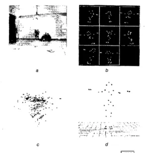
; :.. - _.-_ , , C dFig. 2 Process of extracting 3 0 point in motion capture system a Motion captured environment
b Captured 2D image data in any frame
c 3D data extraction result using epipolar constraints alone
d 3D data extraction result using proposed algorithm
Experimental results: We implemented the algorithm and a test environment on a Pentium I1 PC which had a 350MHz CPU and 64Mbyte memory. The simulated experimental setting consisted of 33 markers within the restricted space, and the initial positions of four virtual cameras. We used Tsai’s calibration method [3] to cal- ibrate the camera system. We evaluated our algorithm using syn- thetic and real data. First, 100 random data sets were used for synthetic data with the Monte Carlo method, which leads to errors in the position of the 3D data due to camera noise and occlusion phenomena. The experimental result shows that 99.2% of 2D markers have reliable correspondences. It takes 0.22s/frame, and 0.11 s/frame when using 3D tracking information. We per- formed the same experiments with real captured 2D data set (2633 frames) acquired from an E v a Hires Motion capture system, which is a high-performance commercial system. The results show 0.33 ghostlframe (compared with 0.583 for the E v a system), 0.0175 missing markedframe (compared with 0.1525 for the E v a system). Here, ghosts (false alarm) and missing markers were the main causes of the need to carry out time-consuming post-process- ing in the optical motion capture system. Fig. 2 depicts the proc- ess of 3D data extraction in the second experiment.
Conclusions: An efficient ghost removal method for acquiring reli- able correspondence information for 2D data matching using relaxation labelling has been presented. We have also presented an
enhanced mechanism exploiting 3D marker tracking information in order to achieve substantial savings in computation time.
Experimental results illustrate that the proposed method is likely to be very useful for acquiring accurate and stable multi- view correspondence information and obviating the need for very time-consuming post-processing in optical motion capture system. Acknowledgment: The authors gratefully acknowledge the financial support of the Electronics and Telecommunications Research Institute (ETRI), Korea.
0 IEE 2000
Electronics Letters Online No: 20000553 DOI: 10.1049/el:20000553
Dong Hoon Lee and Soon Ki Jung (Department of Computer Engineeinrg. Kyungpook National University, 1370 Sankyuk-dong, Puk- gu, Taegu, 702-701, Korea)
E-mail: skjung@knu.ac.kr
Kwangyun Wohn (Department of Computer Dcience, Korea Advanced Institute of Science and Technology, 373-1 Kusong-dong, Yusong-gu. Taejon, 305-701, Korea)
21 February 2000
References
HONG, SHEN, LI, K., PAN, Y., YOUNG, G.H., and ZHENG, s.Q.:
‘Performance analysis for dynamic tree embedding in k-partite networks by a random walk’, J. Parallel Distributed Comput., 1998, 50, pp. 144-156
WELCH, G., and BISHOP, G.: ‘An introduction to the Kalman filter’.
TR 95-041, University of Carolina at Chapel Hill, 1995
TSAI, R.Y.: ‘An efficient and accurate camera calibration technique for 3-D machine vision’. Proc. IEEE Computer Society Conf. Computer Vision and Pattern Recognition, June 1986, pp. 364-374
ZHANG, z., and FAUGERAS, 0.: ‘3D dynamic scene analysis’
(SpringerVerlag, Berlin, Heidelberg, NY, 1992)
Shadow generation from stereo images
Jen-Hui Chuang, Lou-Wei
Kuo,
Hao-JuiKuo
and Jain-Shing LiuA novel approach to generating object shadows using two dimensional (2D) information is presented. Existing approaches to shadow generation are generally based on 3D geometry. The proposed method is based on deriving accurate shadows of a 3D object using only stereo images of the object taken from two different viewpoints. The approach can be extended easily to solve more general problems which involve multiple objects as well as multiple planar surfaces on which object shadows are to be cast. Introduction: For computer generated 3D scenes, shadows are cm- cia1 to the realism of synthetic 2D images. Existing approaches to shadow generation are generally based on 3D geometry. Relevant 3D data required in the shadow computation include the object model, the location of light sources and the surfaces on which the object shadows are to be cast. A survey of shadow algorithms can be found in [l]. For the scan-line shadow algorithm presented in [2], polygonal boundaries are projected onto the scanned object and then projected onto the viewing screen during the display phase. Preprocessing is performed to determine pairs of objects that can interact to produce shadows. In [3], volumes which enclose shadowed regions of space are generated. Their bounda- ries are then used to determine if a visible surface is in shadow. In [4], the visibility of object surfaces viewed from the light source are determined. Those invisible object surfaces correspond to the shadowed area. Apart from the above, other approaches such as the z-buffer [5] and ray tracing [6] techniques have also been devel- oped to generate shadows.
Shadow region derivation: In the following, we present a method of using cross-ratios to derive accurate shadows of a 3D object which only requires stereo images of the object. In the approach it is assumed that at least five reference points on the base plane, upon which the object shadow is to be cast, can be identified in the
images. For example, Fig. l a and b show stereo images of an object, and a base pentagon formed by the five reference points, obtained from viewpoints Vl and V,, respectively. The base plane region blocked by the object in Fig. la, the border of which is shown with solid line segments in Fig.
IC,
corresponds to the shadow cast on the base plane due to a point light source located at VI. Fig. Id shows the object and its shadow obtained for Fig. lb with the shadow generation process discussed next.(here, point J can be used in place of point F if a nearer zero denominator in eqn. 1 will not be generated) we have
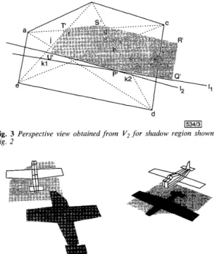
Similarly, k l , can be determined. In exactly the same way, the position of k2 = (kZx, k2,) which is the intersection of 6d and I I can be obtained. With kl and k2, lI can be determined. Thus, the
shadow region shown in Fig. 3 can be obtained from the extended lines of its border segments. Figs. 4 and 5 show additional shadow generation results for simulated and real data, respec- tively.
b
a b
d
1534/31 Fig. 3 Perspective view obtained f r o m V, for shadow region shown in
Fig. 2
C d
Fig. 1 Object images f r o m different viewpoints and generated shadow a Object image obtained from viewpoint V I
b Object image obtained from viewpoint V2
c Base plane region blocked by object as seen from V I d Shadow generated from light source located at V I
In Fig.
IC,
if the five reference points can be located precisely, we can also identify four reference points along each diagonal of the pentagon: two end points of the diagonal, and the intersec- tions of that diagonal with two other diagonals. To locate the extended line of a border segment of the blocked base region, at least two of its intersections with the extended lines of the diago- nals of the pentagon need to be found.L1
I
.Ua b
,
1534/41 Fig. 4 Shadows of airplane generatedfrorn light sources located at two
different viewpoints
a b
1534/51
Fig. 5 Real image and object and additional shadow generated using
second image a Real image of box
b Object and additional shadow generated using second image (not shown)
1534/21
Fig. 2 Object shadow generated froin light source located at V , Consider for example point K l , which is the intersection of BE and L1 in Fig. 2 and the corresponding kl = ( k l x , kl,), which is the intersection of 61; and lI in Fig. 3. According to the view- invariant property of the cross-ratio
Bh'l
.
F E F K 1 . B E-- - R
Conclusions: A novel approach to generating shadows is presented in this Letter. Unlike existing shadow algorithms which require 3D object models, the proposed approach works with stereo images of polyhedral objects placed on a base plane from which five reference points can be identified. The approach can be extended easily to take into account more general situations where shadows of multiple objects are cast onto polyhedral surfaces. Acknowledgment: This work was supported by the National Sci- ence Council, Republic of China, under grant NSC88-2213-E009- 062.
0 IEE 2000
Electronics Letters Online No: 20000552 DOI: IO, 1049/el:20000552
29 February 2000 carrier absorption present in the as-anodised wafers and extends the operating range of the waveguides into the visible part of the snectrum.
-r Jen-Hui Chuang. Lou-Wei Kuo. Hao-Jui Kuo and Jain-Shing Liu
CACM, 1980, 23, (6), pp. 343-349
Self-aligned oxidised porous silicon optical
waveguides with reduced loss
N. Vorozov,
L.
Dolgyi, V. Yakovtseva,V. Bondarenko,
M.
Balucani,G.
Lamedica,A.
Ferrari,G.
Vitrant,J.E.
Broquin,T.M.
Benson,H.F.
Arrandand P.
SewellA report is presented into the fabrication of self-aligned oxidised porous silicon optical waveguides, the optical losses of whch at both visible and infrared wavelengths are sigtutkantly reduced, to around the 1dBcn-' limit widely considered as critical for
application success.
Introduction: Silicon is an attractive base material to consider for optoelectronics applications because of the cost-effective high per- formance level of silicon-based electronic circuits. Porous silicon is a widely studied material in this regard because of its significant potential for the realisation of silicon optoelectronic integrated cir- cuits (OEICs). Because the refractive index of porous silicon can be controlled over a wide range, by varying the porosity, it is valid to consider the material for forming waveguide interconnects. We have previously demonstrated a number of approaches for form- ing porous silicon based waveguides [ 1 - 51, operating at visible to
infrared wavelengths. A disappointing feature of all these reported waveguides is that their optical losses have consistently been >4dBcn-', although filling the pores of the porous silicon by a material of higher refractive index than that of air was successful in reducing interfacial scattering loss [SI. In this Letter we report optical waveguides based on porous silicon the losses of which are consistently and reproducibly below the 1 dBcn-' limit widely regarded as critical to technological success. These waveguides are formed using a development of the 'self-aligned' method described in [l - 31. They provide three-dimensional optical confinement, yet
do not require epitaxy or implantation processes, and therefore offer sigmfkant processing and cost advantages over other tech- nologies.
Sample preparation: Porous silicon materials offer a wide range of possible refractive indices, determined by the porosity. The refrac- tive index of the material decreases with an increase in the poros- ity [6]. The porosity may, in turn, be controlled through the anodisation conditions. The nature and sue of the pores in porous silicon are dependent on the dopant density and type of the start- ing material. Generally, p- material produces interfacial roughness [7] which manifests itself as a scattering loss in the waveguide. Bet- ter uniformity can be achieved with a p+ starting wafer and, in the present work, n+ wafers. Subsequent oxidation to form oxidised porous silicon (OPS) removes the contribution to loss from free
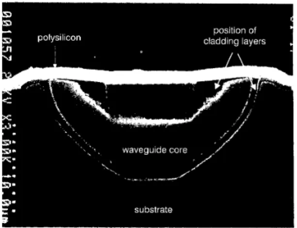
Fig. 1 SEM micrograph of cross-section of porous silicon waveguide formed using 9p-n wide mask
Cladding layers at top and around core of waveguide have been pref- erentially removed by etching in dilute HF; a protective polysilicon layer is deposited on sample surface
The waveguide samples were prepared from (100) oriented highly doped n+-silicon (p = 0.OlQcm). The wafers were chemi- cally cleaned in a conventional RCA (hydrogen peroxide-ammo- nia-water) mixture for lOmin at 80°C and subsequently rinsed in de-ionised water. A protective silicon nitride layer was deposited and windows 3, 5,7, and 9 p n wide opened in this by photolitho- graphic patterning and plasma etching, taking particular care not to unintentionally etch the wafer surface. The photoresist was then removed and the sample re-cleaned. The porous silicon waveguides were then formed by a two-stage anodisation process in an electrolyte mixture composed of 48% hydrofluoric acid and isopropanol (1:2). The first anodisation was to a depth of - 8 p n using a current density of 20-25mAcm2, the second to a further 1-2pn at a current density of 4@50mAcm2. The wafer was then cleaned in de-ionised water for lOmin and the silicon nitride layer removed in a hydrofluoric acid water solution (1:lO) in the dark. After further cleaning in de-ionised water the porous silicon underwent a three-stage oxidation procedure in a manner similar to that proposed in [8]: 60min at 300°C in dry oxygen, 60min at 900°C in dry oxygen and finally at 1150°C for 35min in wet oxy- gen. The temperature was then gradually reduced to 900°C over 50min. The oxidation at 1150°C is crucial for densifying the oxi- dation in what will become the core region of the waveguide. Experimental charucterisution: The structure of the waveguides formed by this procedure has a buried 'crescent shaped' core region of densified oxidised porous silicon and upper and lower cladding regions comprising porous silicon dioxide. This is con- firmed by Fig. 1 which shows a scanning electron microscope (SEM) micrograph of the cross-section of this waveguide formed using a 9 p n wide mask after etching with a 5% aqueous solution of hydrofluoric acid for 2min to highlight the various regions of the waveguide. This etchant removed the oxide from the top and bottom of the waveguide cross-section because in these regions the oxide is porous silicon dioxide which offers a huge surface area to the etchant solution, so increasing its etching rate above that of the densified oxide core. The layer on the top of the sample is made of polysilicon. This polysilicon layer was deposited onto the surface of the wafer before cleaving to enable a good, damage- free, cleaved surface to be obtained and to ensure that the cross- section of the waveguide was etched but not the sample surface. Mask windows of 3, 5 , 7 and 9pm produced waveguides with widths of 18, 20, 22 and 24pn, respectively.
The insertion losses of four sets of waveguides, each 1.32cm long, 10pm thick, and 18, 20, 22, and 24pm wide were measured at 690, 830 and 980nm. Results obtained are presented in Table 1. The coupling loss increases as the waveguide width is reduced, but