國 立 交 通 大 學
電信工程學系碩士班
碩士論文
使用鏈路調節與多輸入多輸出編碼改善
正交分頻多工無線網路效能之研究
Throughput Enhancement via Link Adaptation and
MIMO Coding in OFDM-Based WLANs
研 究 生:曹祐瑞 Student: Yu-Jui Tsao
指導教授:李大嵩 博士 Advisor:
Dr. Ta-Sung Lee
使用鏈路調節與多輸入多輸出編碼改善
正交分頻多工無線網路效能之研究
Throughput Enhancement via Link Adaptation and
MIMO Coding in OFDM-Based WLANs
研 究 生:曹祐瑞
Student:
Yu-Jui
Tsao
指導教授:李大嵩 博士 Advisor:
Dr. Ta-Sung Lee
國立交通大學
電信工程學系碩士班
碩士論文
A Thesis
Submitted to Institute of Communication Engineering
College of Electrical Engineering and Computer Science
National Chiao Tung University
in Partial Fulfillment of the Requirements
for the Degree of
Master of Science
in
Communication Engineering
June 2004
Hsinchu, Taiwan, Republic of China
使用鏈路調節與多輸入多輸出編碼改善
正交分頻多工無線網路效能之研究
學生:曹祐瑞
指導教授:李大嵩 博士
國立交通大學電信工程學系碩士班
摘要
日益增多的各式無線服務需求,如語音、資料傳輸及多媒體,促進了高速無 線區域網路的蓬勃發展。IEEE 802.11 是眾多致力於標準化無線區域網路之媒介存 取與實體層的主要力量之一。其中於媒介存取控制層規範了兩種通道存取機制─ 基本存取機制與請求發送⁄允許發送存取機制。此外,延伸的IEEE 802.11a 透過 實體層的正交分頻多工技術可實現6 Mbps 至 54 Mbps 之高速傳輸。在多傳輸速 率的系統中,鏈路調節顯得愈加重要,其作用在於可動態地轉換傳輸速率以配合 變動之通道狀態。在本論文中,吾人所提出之鏈路調節演算法可更適當地利用 IEEE 802.11a 無線區域網路之媒介存取與實體層。此鏈路調節演算法可根據通道 狀態、競爭站台之多寡與資料長度選擇存取機制與傳輸速率之最佳組合以提升固 有之無線區域網路效能。再者,多輸入多輸出編碼與正交分頻多工技術之結合被 視為提昇新世代無線通訊系統傳輸速率之前瞻技術。依據機能之不同,多輸入多 輸出編碼可分為兩類。其中空間分集之作用在於改善鏈路之可靠度,另一方面, 空間分工則著墨於增加使用頻譜的效率。吾人對所提出之鏈路調節演算法進行修 改,使其可選取適當的多輸入多輸出編碼,以適應當下環境提供良好的鏈路品質 或提昇傳輸速率,進而改善無線網路之效能。最後,藉由電腦模擬結果驗證上述 方法之表現,吾人可證實其在室內無線環境有優異的效能。Throughput Enhancement via Link Adaptation and
MIMO Coding in OFDM-Based WLANs
Student: Yu-Jui Tsao
Advisor: Dr. Ta-Sung Lee
Institute of Communication Engineering
National Chiao Tung University
Abstract
The increasing demand for all types of wireless services (e.g. voice, data, and multimedia) promotes fast growing of the high-speed wireless local area networks (WLANs). One of the major efforts in standardizing the medium access control (MAC) and physical (PHY) layers for WLANs is IEEE 802.11. It defines two channel access mechanisms, the basic and RTS/CTS access mechanism, at the MAC layer. Besides, the extended IEEE 802.11a achieves high data rates ranging from 6 Mbps to 54 Mbps by using orthogonal frequency division multiplexing (OFDM) at the PHY layer. With multiple rates, link adaptation (LA), a process to dynamically switch data rates to best match the varying channel condition, becomes increasingly important. In this thesis, we propose an LA algorithm to better exploit the MAC and PHY layer in the IEEE 802.11a WLAN. According to the channel condition, number of contending stations, and data length, the proposed LA algorithm chooses the optimum combination of the access method and data rate to achieve higher throughput in the inherent IEEE 802.11a WLAN. Furthermore, the combining of multiple-input multiple-output (MIMO) coding with OFDM is regarded as a promising technique for enhancing the data rates of next generation wireless communication systems. The MIMO coding can be categorized into two types based on their functionality. Spatial diversity (SD) is used to improve the link reliability while spatial multiplexing (SM) increases the spectral efficiency. For further improvements in the WLAN’s throughput, we modify the proposed LA algorithm so that it can choose the appropriate MIMO coding as well to provide the better link quality or higher data rate according to channel condition. Finally, we evaluate the performance of the proposed algorithms by computer simulations, and confirm that they work well in indoor wireless environments.
Acknowledgement
I would like to express my deepest gratitude to my advisor, Dr. Ta-Sung Lee, for his enthusiastic guidance and great patience. Heartfelt thanks are also offered to all members in the Communication Signal Processing (CSP) Lab for their constant encouragement. Last but not least, I would like to show my sincere appreciation and love to my family for their life-long love and support.
Contents
Chinese Abstract
I
English Abstract
II
Acknowledgement III
Contents IV
List of Figures
VI
List of Tables
VIII
Abbreviations IX
Notations
XI
1 Introduction
1
2 Overview of IEEE 802.11a Systems
4
2.1 IEEE 802.11 MAC...4
2.1.1 Basic Access Method ...5
2.1.2 RTS/CTS Access Method ...8
2.2 IEEE 802.11a OFDM PHY...10
2.2.1 OFDM Overview ...11
2.2.2 IEEE 802.11a PHY Frame Structure ...12
2.2.2.2 SIGNAL Field and DATA Field...16
2.3 Summary...18
3 Link Adaptation for IEEE 802.11a Systems
27
3.1 Collision Probability ...283.2 MAC/PHY Layer Overheads...33
3.3 Error Performance of PHY modes...35
3.3.1 Bit Error Probability ...35
3.3.2 Frame Error Probability ...36
3.4 Effective Goodput Computation...38
3.5 Link Adaptation Scheme...44
3.6 Computer Simulations ...47
3.7 Summary...48
4 Link Adaptation for MIMO-Enhanced 802.11a Systems 59
4.1 MIMO Systems...614.1.1 MIMO Channel Model ...61
4.1.2 Performance Analysis of STBC-Enhanced 802.11a PHY ...63
4.1.3 Performance Analysis of VBLAST-Enhanced 802.11a PHY ...66
4.2 Link Adaptation Scheme...68
4.3 Modified MAC/PHY Layer Overheads ...71
4.4 Computer Simulations ...73
4.5 Summary...75
5 Conclusion
85
List of Figures
Figure 2.1 Timing of frame transmissions under basic access method...19
Figure 2.2 Timing of frame transmissions under RTS/CTS access method ...20
Figure 2.3 Layer and sublayer defined in IEEE 802.11a standard...21
Figure 2.4 PPDU frame format defined in IEEE 802.11a standard ...21
Figure 2.5 Structure of PLCP preamble field defined in IEEE 802.11a standard...22
Figure 2.6 Bit assignment in SIGNAL field...22
Figure 2.7 Bit assignment in SERVICE field...23
Figure 3.1 Markov chain model for the backoff window size ...49
Figure 3.2 Solving for collision probability of IEEE 802.11a DCF system as the number of contending stations increases ...50
Figure 3.3 Collision probability of IEEE 802.11a DCF system versus the number of contending stations ...50
Figure 3.4 Frame formats of IEEE 802.11 MAC ...51
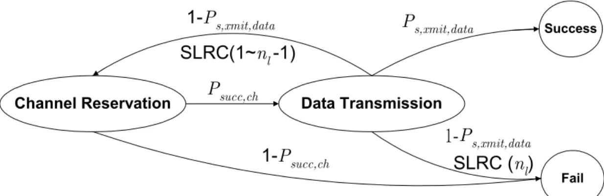
Figure 3.5 The upper bound BER performance of eight PHY modes of IEEE 802.11a versus the average received SNR per symbol ...52
Figure 3.6 Two stages of RTS/CTS access method...52
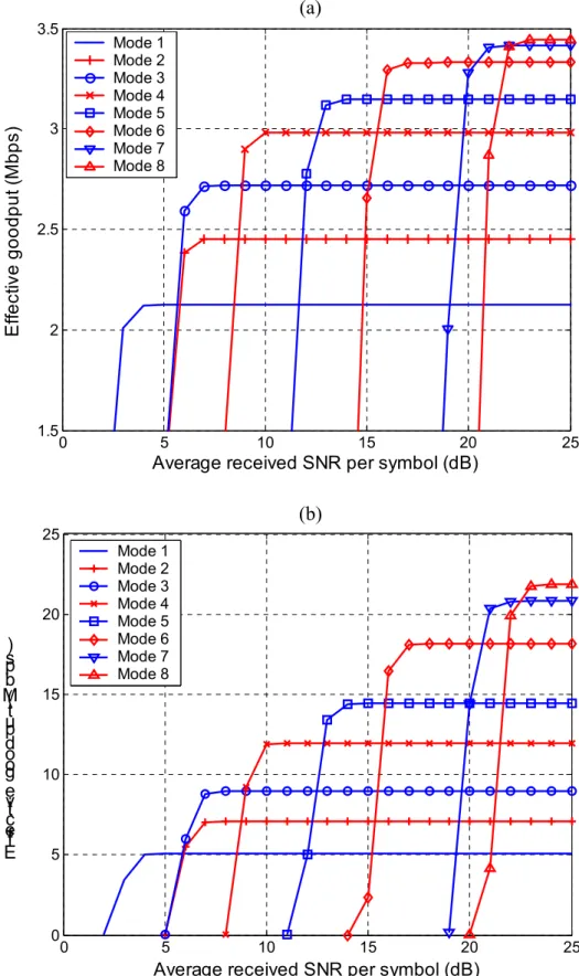
Figure 3.7 Effective goodputs of different PHY modes using RTS/CTS access method versus average received SNR per symbol. Assume there are five contending stations in IEEE 802.11a WLAN. ...53
Figure 3.8 Adaptive PHY mode selection for improving the effective goodput using RTS/CTS access method in IEEE 802.11a WLAN with five contending stations ...54
Figure 3.9 Adaptive PHY mode selection for improving the effective goodput using basic access method in IEEE 802.11a WLAN with five contending stations ...54
Figure 3.10 Maximum effective goodput of different PHY modes using basic access method versus number of contending stations in IEEE 802.11a WLAN MSDU size: 2,000 octets ...55 Figure 3.11 Proposed system architecture for link adaptation ...55 Figure 3.12 Performance evaluation for proposed link adaptation by NS-2 with
2-node topology. 2,000-octet MSDU is generated with CBR traffic...56
Figure 4.1 Linear combining for detection of STBC at kth subcarrier in 2x2
MIMO-OFDM systems...77
Figure 4.2 Equivalent maximum ration combining model for STBC at kth
subcarrier in 2x2 MIMO-OFDM systems ...77
Figure 4.3 Equivalent scaled AWGN channel model for STBC at kth subcarrier in
2x2 MIMO-OFDM systems...78
Figure 4.4 Instantaneous upper bound BER performance of eight PHY modes of
STBC-enhanced 802.11a versus SNR (Es/N0) ...78
Figure 4.5 VBLAST architecture at kth subcarrier in 2x2 MIMO-OFDM systems79
Figure 4.6 Instantaneous simulated and upper bound BER of VBLAST system
with QPSK modulation versus SNR (Es/N0)...79
Figure 4.7 Instantaneous upper bound BER performance of eight PHY modes of
VBLAST-enhanced 802.11a versus SNR (Es/N0) ...80
Figure 4.8 Modified frame formats of IEEE 802.11 MAC for link adaptation ...80
Figure 4.9 Modified PPDU frame format of IEEE 802.11a OFDM PHY for link
adaptation...81 Figure 4.10 Distribution of squared Frobenius norm and minimum singular value
generated by 20 independent flat Rayleigh fading 2x2 MIMO channel matrix ...81
Figure 4.11 Maximum goodput for adaptive PHY mode and MIMO coding for 2x2
MIMO-enhanced 802.11a systems ...82 Figure 4.12 Maximum goodupt for adaptive PHY mode and MIMO coding for 2x2 MIMO-enhanced 802.11a systems and standard IEEE 802.11a system with h =2 1...82
List of Tables
Table 2.1 Rate-dependent parameters of IEEE 802.11a PHY ...24 Table 2.2 Timing-related parameters of IEEE 802.11a PHY ...25 Table 2.3 Contents of RATE field...26
Table 3.1 Adaptive PHY mode and MAC mechanism selection corresponding to
given channel condition with five contending stations...57
Table 3.2 Adaptive PHY mode and MAC mechanism selection corresponding to
given channel condition with 20 contending stations...58
Table 4.1 Contents of MIMO subfield in modified 802.11 MAC frame formats 83
Table 4.2 Contents of RATE subfield in modified 802.11 MAC frame formats .83
Table 4.3 Adaptive PHY mode and MIMO coding selection for 2x2 channel
matrix with 2,000 MSDU and five contending stations
2
min
4.0822, 0.85341
F = λ =
H ...84
Table 4.4 Adaptive PHY mode and MIMO coding selection for 2x2 channel
matrix with 2,000 MSDU and five contending stations
.9888 0.15856 2 min 3 , F = λ = H ...84
Abbreviation
ACK acknowledgement
AWGN additive white Gaussian noise
BER bit error rate
BLAST Bell laboratories layered space-time
BPSK binary phase shift keying
BSS basic service set
CSMA/CA carrier sense multiple access with collision avoidance
CTS clear-to-send
CW contention window
DCF distributed coordination function
DIFS DCF inter frame space
EIFS extended inter frame space
FCS frame check sequence
FEC forward error correction
FFT fast Fourier transform
IFS inter frame space
ISI inter-symbol interference
LA link adaptation
MAC medium access control
MPDU MAC protocol data unit
MSDU MAC service data unit
NAV network allocation vector
OFDM orthogonal frequency division multiplexing
PAM pulse amplitude modulation
PCF point coordination function
PHY physical layer
PIFS PCF inter frame space
PLCP PHY convergence procedure
PMD physical medium dependent
PPDU PLCP protocol data unit
PSDU PHY service data unit
QAM quadrature amplitude modulation
QPSK quadrature phase shift keying
RSH reservation subheader
RTS: request-to-send
SIFS short inter frame space
SISO single-input single-output
SLRC station long retry count
SNR signal-to-noise ratio
SSRC station short retry count
STBC space-time block code
U-NII unlicensed national information infrastructure
VBLAST vertical BLAST
Notations
CWmin minimum contention window size
CWmax maximum contention window size
Hk kth-subband MIMO channel matrix
l data payload length
m PHY mode
n number of contending stations
nl long retry limit
ns short retry limit
nR number of receive antennas
nT number of transmit antennas
N0 power spectral density of AWGN
TFFT FFT interval
GI
T OFDM guard interval
TPREAMBLE duration of the PLCP preamble
SYM
T OFDM symbol duration
x transmitted signal
y received signal
γ average received SNR per symbol
,min
k
λ minimum singular value of Hk
2
k F
Chapter 1
Introduction
The increasing demand for all types of wireless services (e.g. voice, data, and multimedia) promotes fast growing of high-speed wireless local area networks (WLANs). One of the major efforts in standardizing the medium access control (MAC) and physical (PHY) layers for WLANs is IEEE 802.11 [1].
In IEEE 802.11 MAC, the distributed coordination function (DCF) is the fundamental access method. There are two techniques used for packet transmitting in DCF. The default one is a two-way handshaking mechanism, also known as basic access method. The other optional one is a four-way handshaking mechanism, which uses the request-to-send/clear-to-send (RTS/CTS) technique to reserve the channel before data transmission, also known as RTS/CTS access method. One of the benefits of the RTS/CTS access method is to increase the system performance by minimizing the amount of time wasted when collisions occur on long data frames. However, the RTS/CTS technique also increases two additional overheads without any payload, thus decreasing efficiency. For that reason, the use of the RTS/CTS access method is under the control of the manageable object, RTS_Threshold, which indicates the data length under which the data frames should be sent without RTS/CTS [2][3].
IEEE 802.11a [4] is a high-speed physical layer defined for the 5 GHz U-NII bands as a supplement to the existing IEEE 802.11 WLAN standard. It provides eight
PHY modes with transmission rates ranging from 6 Mbps up to 54 Mbps by using orthogonal frequency division multiplexing (OFDM) [5] as its underlying radio technology.
The mechanism to select one out of multiple available transmission rates at a given time is referred to as link adaptation (LA) [6]. The principle of LA is to adapt the transmission rates to best match the channel conditions in order to achieve one or several performance criteria, like system throughput maximization, bit error rate (BER) ,and etc. LA algorithms for IEEE 802.11 WLANs have been studied by many researchers [7-11]. However, these existing approaches focus on the PHY modes only. The transmission duration of a fixed-length data fluctuates according to the transmission rate. Therefore, RTS_Threshold, the only parameter for deciding whether the RTS/CTS access method is applied, is not sufficient now.
To address this issue, we propose an integrated LA algorithm that better exploits the inherent MAC and PHY layers by choosing the best combination of the MAC access method and PHY mode according to the data frame length, wireless channel condition, and number of contending stations for maximizing the system goodput. Here, the goodput refers to the useful data rate the user actually enjoys after all the overheads are accounted for, including the MAC/PHY overheads, backoff delay, interframe intervals, and the potential frame retransmission times.
Another aim of this thesis is to enhance the performance of the current 802.11a standard by employing multiple antennas at the transmitter and receiver. The combining of multiple-input multiple-output (MIMO) coding with OFDM is considered as a promising technique for enhancing the data rates of next-generation wireless communication systems, especially WLAN systems. An advantage of WLAN systems is that they are mainly deployed in indoor environments. These environments are typically characterized by richly scattered multipaths. As explained in [12], this is a
good condition for having a high MIMO capacity.
MIMO coding techniques can basically be split into two groups: spatial diversity [13], e.g. space-time block code (STBC) [14][15] and spatial multiplexing [12][16][17], e.g. Bell laboratories layered space-time (BLAST) [18][19]. While STBC improves the link quality of the system by exploiting the spatial and temporal diversity, BLAST significantly improves the spectral efficiency of the system at the cost of poor error performance. We compare these two techniques using the performance metric of goodput defined above, and are able to select the most suitable MIMO technique under the given channel condition to increase the link throughput in an MIMO-enhanced 802.11a WLAN system.
The rest of this thesis is organized as follows. In Chapter 2, we introduce the principles of mandatory DCF mechanism of IEEE 802.11 MAC and OFDM characteristics of 802.11a PHY. Based on these understandings, we analyze the goodput performance of the 802.11a systems and propose an integrated LA algorithm for adapting MAC access and PHY mode in Chapter 3. In Chapter 4, we modify the proposed LA algorithm for MIMO-enhanced 802.11a systems. In Chapter 5, we conclude this thesis and propose some potential future works.
Chapter 2
Overview of IEEE 802.11a Systems
In this chapter, we will describe the principles of the IEEE 802.11 MAC in Section 2.1. In Section 2.2, we will introduce some characteristic in IEEE 802.11a PHY, which is an OFDM-based WLAN standard.
2.1 IEEE
802.11
MAC
IEEE 802.11 MAC provides a fair access to the shared wireless medium through two different mechanisms: a mandatory contention-based access protocol, called the distributed coordination function (DCF), and an optional polling-based protocol, called the point coordination function (PCF) [1]. PCF is very rarely implemented in currently available devices. In this thesis, we consider only the DCF protocol, which is prevailing in the market today.
DCF is based on carrier sense multiple access with collision avoidance (CSMA/CA). With CSMA, a station wishing to transmit first listens to the medium to determine if another transmission is in progress (carrier sense). If the medium is in use, the station must wait. If the medium is idle, the station transmits. It may happen that two or more stations attempt to transmit at about the same time. If this happens, there
will be a collision; the data from both transmissions will be disarranged and not received successfully. To reduce the collision probability between multiple stations accessing the wireless medium, collision avoidance (CA) is carried out in two ways: i) by following a backoff procedure before the data transmission, and ii) by keeping track of the expected duration of ongoing transmissions. The latter technique is termed virtual carrier sensing and practically realized by recording the transmission duration information contained in the request-to-send (RTS), clear-to-send (CTS), and data frames.
Under DCF, data frames are transmitted via two methods. The essential method used in DCF is called the basic access method. The 802.11 standard also provides an alternative way of transmitting data frames, namely the RTS/CTS access method
2.1.1 Basic
Access
Method
In IEEE 802.11, priorities for accessing to the wireless medium are controlled by the use of inter frame space (IFS) intervals, i.e. time intervals between the transmissions of consecutive frames. The standard defines four different IFS intervals: short IFS (SIFS), PCF IFS (PIFS), DCF IFS (DIFS), and extended IFS (EIFS). The SIFS is the smallest followed by PIFS, DIFS, and EIFS. After an SIFS, only acknowledgement (ACK), CTS and data frames may be sent. The use of PIFS and DIFS is to separate the PCF and DCF modes.
Under the basic access method, a station, when starting a new frame transmission, shall sense the wireless medium to determine if another station is transmitting. If the station detects that the wireless medium has been idle for more than a time interval called DIFS, the station can transmit the data frame immediately. If the medium is sensed as busy, the station waits until the channel becomes idle, then defers for an
extra DIFS interval. If the medium remains idle, the MAC starts the backoff procedure by selecting a random backoff count since collisions are most likely to happen just after the medium becomes free. The backoff counter (how to select the random backoff count is detailed below) is decremented as long as the channel is sensed idle, frozen when a transmission is detected on the channel, and reactivated when the channel is sensed idle again for more than a DIFS. The station transmits when the counter reaches zeros.
To select the random backoff count, each station maintains a contention window (CW) value. The backoff count, in the unit of Slot_Time, is determined as a random integer drawn from a uniform distribution over the interval [0, CW]. The value of CW is initially assigned a CWmin, and increases exponentially when a transmission fails. After any unsuccessful transmission attempt, another backoff is performed with a new CW value determined as follows:
(2.1)
2 ( 1) 1
CW ⇐ ⋅ CW + −
The set of CW values are sequentially ascending integer powers of 2 minus 1. Once the CW value reaches the value of CWmax, it remains at the value of CWmax until it is reset. The CW value is reset to CWmin after a successful transmission or after reaching the maximum retry limit. If the maximum retry limit (ShortRetryLimit or
LongRetryLimit) is reached, the retransmission attempts shall cease, and the frame
shall be discarded.
Every station maintains a station short retry count (SSRC) as well as a station long retry count (SLRC), both of which have an initial value of zero. SSRC indicates the retransmission number of the RTS frames or the data frames transmitted by the basic access method. SLRC indicates the retransmission number of data frames when
the RTS/CTS technique is used. The specified limits of SSRC and SLRC are
ShortRetryLimit and LongRetryLimit (typically 7 and 4), respectively. The SSRC is
reset to 0 whenever a CTS is received in response to an RTS or whenever an ACK is received in response to a data frame. The SLRC is also reset to 0 whenever an ACK is received in response to a data frame when the RTS/CTS technique is used.
One important characteristic of the IEEE 802.11 MAC is that an ACK frame shall be transmitted by the receiver after a successful data frame reception. Only after receiving the ACK frame correctly, the transmitter assumes that the data frame was delivered successfully. SIFS, which is smaller than DIFS, is the time interval between the data frame reception and ACK frame transmission. Using this smallest IFS interval between transmissions within the frame exchange sequence prevents other stations, which are required to wait for the medium to be idle for a longer time interval, e.g. at least a DIFS time, from attempting to use the medium, thus giving priority to completion of the frame exchange sequence in progress. If the ACK frame is not received within an ACK_Timeout period after the data transmission, the data frame is retransmitted after another random backoff. When the data frame is correctly transmitted and the corresponding ACK is received, the station performs a DIFS deference and another random backoff process, which is often referred to as “post-backoff” to avoid channel capture.
When a data frame is transmitted, all the other stations hearing the data frame adjust their network allocation vector (NAV), which is used for virtual carrier sensing at the MAC layer indicating the period of time in which the channel will remain busy, based on the duration field value in the data frame, which includes an SIFS interval and the transmission time of the ACK frame following the data frame.
basic access method consists of the following phases: the DIFS deferral phase, backoff phase if necessary, data transmission phase, SIFS deferral phase, and ACK transmission phase. The timing of successful frame transmission is illustrated in Figure 2.1(a). In Figure 2.1(b), if no ACK frame is received after an SIFS interval, due possibly to collision or an erroneous reception, i.e. received with an incorrect frame check sequence (FCS), the transmitter will contend again for the medium to retransmit the data frame after an ACK_Timeout. However, if an ACK frame is received in error, the transmitter will recontend for the medium to retransmit the data frame after an EIFS interval, as shown in Figure 2.1(c).
2.1.2 RTS/CTS
Access
Method
DCF also defines an optional way, named the RTS/CTS access method, of transmitting data frames, which involves the transmission of special short RTS and CTS frames prior to the transmission of the actual data frame. Before transmitting a data frame, the source station reserves the channel by sending an RTS after a DIFS (along with backoff count if necessary) long idle channel. When the receiving station detects an RTS frame, it responds, after an SIFS interval, with a CTS frame. The source station is allowed to transmit its data frame only if the CTS frame is correctly received. If the CTS frame is not received by the source station, it is assumed that a collision occurred and an RTS retransmission is scheduled. After the data frame is received by the receiving station, an ACK frame is sent back to the source, verifying successful data reception.
The RTS and CTS frames carry the information of the duration of frame transmission. This information can be read by any listening station, which is then able to update the NAV containing the information of the time period in which the channel
will remain busy. Therefore, when a station is hidden from either the transmitting or receiving station, by detecting just one frame among the RTS and CTS frames, it can suitably delay further transmission, and thus avoid collision. That is, the successful exchange of small messages, RTS and CTS, reserves the area within the range of the transmitter and receiver for the intended transmission period guaranteeing undisturbed transmission for the longer data frame.
The RTS/CTS access method allows increasing the system performance by minimizing the amount of time wasted when collisions occur on long data frames. More specifically, if a collision occurs with two or more small RTS frames, the time loss is smaller compared to the collision of long data frames. On the other hand, the RTS/CTS technique decreases efficiency since it transmits two additional frames without any payload. For that reason, the use of the RTS/CTS access method is under the control of the manageable object, RTS_Threshold, which indicates the data length under which the data frames should be sent without RTS/CTS. The data frame size is the only parameter that is used to decide whether the mechanism is applied. The RTS_Threshold parameter is not fixed in the IEEE 802.11 standard and has to be set separately by each station.
To summarize the discussion above, a transmission cycle under the RTS/CTS access method consists of the following phases: the DIFS deferral phase, backoff phase if necessary, RTS transmission phase, SIFS deferral phase, CTS transmission phase, SIFS deferral phase, data transmission phase, SIFS deferral phase, and ACK transmission phase. The timing of successful frame transmission is illustrated in Figure 2.2(a). On the other hand, if no CTS frame is received, due possibly to collision or an erroneous reception of the RTS frame, as shown in Figure 2.2(b), or if no ACK frame is received, due possibly to an erroneous reception of the data frame, as shown in Figure 2.2(c), after an SIFS interval, the transmitter will contend again for the medium
to retransmit the RTS frame after a CTS_Timeout or an ACK_Timeout. However, if a CTS or an ACK frame is received in error, the transmitter will recontend for the medium to retransmit the RTS frame after an EIFS interval, as shown in Figure 2.2(d) and Figure 2.2(e), respectively.
2.2
IEEE 802.11a OFDM PHY
The PHY layer is the interface between the MAC layer and wireless medium, which transmits and receives data frames over the shared wireless medium. In order to allow IEEE 802.11 MAC to operate with minimum dependence on the physical medium dependent (PMD) sublayer, a PHY convergence procedure (PLCP) sublayer is defined. The frame exchange between MAC and PHY is under the control of the PLCP sublayer. Figure 2.3 illustrates their relation. During the transmission, the MAC protocol data units (MPDUs) from the MAC layer shall be preceded by a PLCP preamble and a PLCP header to create PLCP protocol data units (PPDUs). The format of the PPDU is shown in Figure 2.4.
IEEE 802.11a is an OFDM-based WLAN standard developed by IEEE 802.11. In July 1998, the IEEE 802.11 standardization group decided to select OFDM as the basis for a new PHY standard extension to the existing 802.11 MAC standard [4]. In the IEEE 802.11a standard, the WLAN system is initially designed to operate in the 5.15-5.35 and 5.725-5.825 GHz unlicensed national information infrastructure (U-NII) bands. There are totally eight non-overlapping 20 MHz channels across the 5.15-5.35 GHz band. The resulting subcarrier frequency spacing is 312.5 kHz (for a 20 MHz with 64 possible subcarrier frequency slots). IEEE 802.11a specifies data rates ranging from 6 to 54 Mbps by using the OFDM technique to achieve high-speed WLAN
communications. Table 2.1 contains a listing of the eight specified PHY modes. Four different modulation schemes are used: binary and quadrature phase shift keying (BPSK/QPSK), 16-quadrature amplitude modulation (16-QAM) and 64-QAM. Each higher performing modulation scheme requires a better channel condition for accurate transmission, making the idea of link adaptation (LA) feasible and important (we will discuss this issue in the later chapter). These modulation schemes are coupled with the various rate forward error correction (FEC) codes. In the IEEE 802.11a standard, the convolutional code is used. The support of transmitting and receiving at the data rates of 6, 12, and 24 Mbps is mandatory in the IEEE 802.11a PHY. The timing parameters associated with the OFDM physical layer is listed in Table 2.2.
2.2.1 OFDM
Overview
OFDM [5] is a modulation scheme that converts a wideband signal into a series of independent narrowband signal placed side-by-side in the frequency domain. The main benefit of OFDM is that the subcarriers in the frequency band can actually overlap one-another in the frequency domain for the orthogonal property of subcarriers. The basic idea is to split the data to be transmitted into a number of parallel data streams, each of which modulates a subcarrier. The data rate per subcarrier is only a fraction of conventional single carrier systems having the same throughput. OFDM communication systems naturally mitigate the problem of multipath propagation with its low data rate per subcarrier. In other words, a multipath (frequency-selective) channel is divided into a number of narrowband flat-fading channels. This is one of the biggest advantages of OFDM modulation.
In order to prevent inter-symbol interference (ISI), a guard interval is implemented by means of a cyclic prefix. Thus, each OFDM symbol is preceded by a
periodic extension of the symbol itself. The total OFDM symbol duration is where T is the guard interval and T is the useful symbol duration. When the guard interval is longer than the excess delay of the radio channel, ISI is eliminated.
SYM GI T GI
T =T +
Pilot tones are often used in OFDM systems for carrier frequency offset and channel estimation refinements. IEEE 802.11a PHY specifies a total of 52 OFDM subcarriers with 48 data subcarriers and 4 pilot subcarriers. Each of the subcarriers is spaced 312.5 kHz apart and a guard interval of 800 ns is added to each symbol making the total symbol duration 4.0 µs.
2.2.2 IEEE 802.11a PHY Frame Structure
As shown in Figure 2.4, a complete PPDU defined in the IEEE 802.11a standard consists of the OFDM PLCP preamble, OFDM PLCP header, PHY service data unit (PSDU), tail bits and pad bits. In the standard, the OFDM PLCP preamble includes two kinds of OFDM training signals with different symbol periods, which are used for synchronization in the receiver. The PLCP header and the following PSDU jointly form the SIGNAL and DATA fields of the PPDU frame. The PLCP header of the PPDU frame is composed of several fields, and the information conveyed in these fields is processed in the receiver to aid the demodulation and delivery of PSDU from the DATA field.
2.2.2.1 PLCP Preamble Field
The main function of the PLCP preamble field is for receiver synchronization, and the structure of the preamble defined in the IEEE 802.11a standard is shown in Figure 2.5. The preamble includes two parts. The first part is composed of 10 repetitions of a short OFDM training signal with a symbol period of 0.8 µs, which is a quarter of the fast Fourier transform (FFT) interval of a normal data OFDM signal, 3.2 µs. The second part of the preamble consists of one cyclic prefix with 1.6 µs and two successive long OFDM training signals with a symbol period 3.2 µs. Note that the length of the cyclic prefix in the second part of the preamble is two times longer than that of a normal data OFDM signal, and the cyclic prefix is a copy of the latter half of the long OFDM training signal. In the following, we will describe the characteristics and functions of the short and long OFDM training signals, respectively.
Short OFDM training signal
A short OFDM training signal consists of 12 subcarriers, which are modulated by the elements of the sequence S, given by
{
}
26, 26 (13 / 6) 0, 0, 1 , 0, 0, 0, 1 , 0, 0, 0, 1 , 0, 0, 0, 1 , 0, 0, 0, 1 , 0, 0, 0, 1 , 0, 0, 0, 0, 0, 0, 0, 1 , 0, 0, 0, 1 , 0, 0, 0, 1 , 0, 0, 0, 1 , 0, 0, 0, 1 , 0, 0, 0, 1 , 0, 0 S j j j j j j j j j j j − = × + − − + − − − − + − − − − + + + j + (2.2)where we number the 53 subcarriers (including dc) from –26 to 26 and the 0-th
subcarrir denotes dc. The multiplication by a factor of (13 / 6) is to normalize the
From the sequence S in (2.2), the subcarrier numbers chosen by the short training signal are a multiple of 4. It means that the short OFDM training signal has the
fundamental frequency of four subcarrier spacings, 4 /TFFT (where the TFFT is the
FFT interval listed in Table 2.2). Hence, the symbol period of the short training signal
is and is a quarter smaller than that of the normal data OFDM signal,
T
/ 4 0.8
FFT
T = µs
FFT. The short OFDM training signals used in the first part of the PLCP preamble
field have two purposes. First, the short training signals provide a convenient way of performing automatic gain control (AGC) and frame detection. There are two general methods used to detect the presence of the frame. One is by correlating the received OFDM training signal with its delayed version, and the other is by matched filtering with the training signal. The second purpose for using short training signals is to perform frequency offset estimation and timing synchronization. In the receiver, by using the short OFDM training signals to estimate the frequency offset, we can have the maximum estimation range of two subcarrier spacings. The IEEE 802.11a standard
specifies that the maximum frequency offset per user shall be less than ppm of
the carrier frequency [20]. As the worst case arising between the transmitter and receiver, the frequency offset will be up to 40 ppm of the carrier frequency seen by the receiver. At a carrier frequency of 5.8 GHz, a 40 ppm of carrier frequency offset is approximately equal to a subcarrier spacing, 312.5 kHz. Hence, the range of frequency offset estimation using the short OFDM training signals can support this case well.
20 ±
Long OFDM training signal
A long OFDM training signal consists of 53 subcarriers (including a zero value at dc), and the subcarriers are modulated by the elements of the sequence L, given by
(2.3)
{
}
26, 26 1, 1, 1, 1, 1, 1, 1, 1, 1, 1, 1, 1, 1, 1, 1, 1, 1, 1, 1, 1, 1, 1, 1, 1, 1, 1, 0, 1, 1, 1, 1, 1, 1, 1, 1, 1, 1, 1, 1, 1, 1, 1, 1, 1, 1, 1, 1, 1, 1, 1, 1, 1, 1 L− = − − − − − − − − − − − − − − − − − − − − −In the IEEE 802.11a standard, the long OFDM training signals are also used to evaluate the frequency offset. The maximum range of frequency offset estimation using the long training signals is only half of a subcarrier spacing which is smaller than that by using the short training signals. However, the smaller estimation range the frequency offset estimator has, the more accurate the estimation result we can gain. Hence, we call frequency offset estimation using the long OFDM training signals as the fine frequency offset estimation and that using short OFDM training signals as the coarse frequency offset estimation. In addition, there is another purpose for the long OFDM training signals used in the second part of the PLCP preamble field. Considering a K-subcarrier OFDM system, the relation among the received OFDM signals, the transmitted OFDM signals and the channel effect is given by
(2.4)
k k k
y =x h⋅
for wherex is the transmitted subsymbol,y is the received subsymbol,
andh is the frequency response of the channel at the kth subcarrier, respectively.
Hence, we can use the long OFDM training signals to perform channel estimation by dividing the received subsymbols by the known elements in (2.3). After channel
1, , , k = … K
k
estimation using the long OFDM training signals, we can use the information of the channel to cancel the channel effect and recover the data subsymbols in the OFDM signals by using the relation described in (2.4).
2.2.2.2 SIGNAL Field and DATA Field
As shown in Figure 2.4, the PLCP header contains the following fields: RATE, LENGTH, a reserved bit, an even parity bit and SERVICE. During the OFDM signal modulation, RATE, LENGTH, the reserved bit and parity bit (with 6 “zero” tail bits appended) constitute a separate single OFDM signal, denoted as SIGNAL. In the transmitter, the SIGNAL field is transmitted with a robust combination of the BPSK modulation and a coding rate of R=1/2. The SEVERICE field of the PLCP header and the PSDU (with 6 “zero” tail bits and pad bits appended) constitute multiple OFDM signals, denoted as DATA. The function of each field in the SIGNAL and DATA fields will be introduced in the following.
SIGNAL field
The SIGNAL field is composed of 24 bits and the bit assignment of each field is illustrated in Figure 2.6. The RATE field occupies the first four bits of the SIGNAL field, and conveys the information about the data rate chosen to transmit the following PSDU. The mapping between the data rate and the content of the RATE field is shown in Table 2.3. By the information from the RATE field, the receiver can determine what type of modulation and what coding rate of the FEC coding are used in PSDU. Bits 5-16 of the SIGNAL field are the LENGTH field, and the information conveyed in this field indicates the number of octets in PSDU, which MAC requests PHY to transmit.
The number of octets in the LENGTH field shall be an unsigned 12-bit integer and has the range from 1 to 4095, and the least significant bit (LSB) shall be transmitted first in time. For the other bits, bit 4 is reversed for future use and bit 17 is a positive parity (even parity) bit for bits 0-16. The last six bits 18-23 constitute the TAIL field of the SIGNAL filed, and all 6 bits are set to zero. The goal of the TAIL field used here is to return the convolutional encoder to the “zero state”. Because the information conveyed in the RATE and LENGTH fields are required for coding the DATA field of the PPDU frame, it is required that these fields can be decoded immediately after the reception of the TAIL field.
DATA field
The DATA field consists of the SERVICE field, PSDU, tail bits and pad bits. In the process of encoding the DATA field into the OFDM signals in the transmitter, all data bits in the DATA field shall be scrambled by a data scrambler. In the receiver, there is a reverse operation performed by a descrambler to recover the data bits. The function of the SERVICE subfield in the DATA field is used to synchronize this descrambler in the receiver. In the DATA field, the SERVICE field occupies first sixteen bits, denoted as bits 0-15, and the bit assignment of the SERVICE field is shown in Figure 2.7. Bits 0-6 of the SERVICE filed are set to zeros and used to synchronize the descrambler in the receiver. The remaining 9 bits (bits 7-15) of the SEVRICE field are reversed for future use and all shall be set to zero. In the DATA field, the tail bits are composed of six bits of “0” and are also used to return the convolutional decoder to the “zero state”. By this procedure, the decoded errors arising in this PPDU frame will not propagate to the next PPDU frame. Hence, we can improve the error probability of the convolutional decoder in the receiver by returning
the convolutional decoder back to “zero state”.
As mentioned, the OFDM system defined in the standard can support eight different data rates. For different data rates chosen to transmit the DATA field, the number of data bits in an OFDM signal, denoted NDBPS, is also different. The relation between NDBPS and data rate is listed in Table 2.1, and the number of the data bits in the DATA field shall be a multiple of NDBPS. To achieve this condition, the pad bits are used to append in the back of the tail bits in the DATA field. The number of pad bits,
NPAD, required is computed from the length of PSDU (LENGTH) as follows:
(2.5)
(
ceil (16 8 LENGTH 6)/ SYM DBPS N = + × + N)
SYM DBPS DATA PAD DATA (2.6) N =N ×N (2.7) LENGTH (16 8 6) N =N − + × +where is a function that returns the smallest integer value greater than or equal
to its argument, N ceil ( )⋅
SYM denotes the number of OFDM signals in the DATA field and
NDATA is the number of bits in the DATA field. These pad bits are all set to “0” and also shall be scrambled by a data scrambler.
2.3 Summary
In this chapter, we introduce the principles of mandatory DCF mechanism of IEEE 802.11 MAC and OFDM characteristics of IEEE 802.11a PHY. Relying on these understandings, we can further analyze the IEEE 802.11a systems in the later chapters.
Busy Medium DIFS Backoff DATA
SIFS ACK
DIFS Backoff DATA
Busy Medium DIFS Backoff DATA
SIFS ACK DIFS
DIFS Backoff DATA
Busy Medium DIFS Backoff DATA ACK Timeout Backoff DATA
Busy Medium DIFS Backoff DATA ACK TimeoutACK Timeout Backoff DATA
Busy Medium DIFS Backoff DATA
SIFS ACK
EIFS Backoff DATA
Busy Medium DIFS Backoff DATA
SIFS ACK EIFS
EIFS Backoff DATA
(a)
(b)
(c)
Figure 2.1: Timing of frame transmissions under basic access method (a) Successful frame transmission (b) Frame retransmission due to data frame failure (c) Frame retransmission due to ACK failure
Busy Medium DIFS Backoff RTS
SIFS CTS
SIFS DATA
SIFS ACK
DIFS Backoff
Busy Medium DIFS Backoff RTS
SIFS CTS
SIFS DATA
SIFS ACK
DIFS Backoff
Busy Medium DIFS Backoff RTS CTS Timeout Backoff
Busy Medium DIFS Backoff RTS CTS Timeout Backoff
Busy Medium DIFS Backoff RTS
SIFS CTS
SIFS DATA ACK Timeout Backoff
Busy Medium DIFS Backoff RTS
SIFS CTS
SIFS DATA ACK Timeout Backoff
Busy Medium DIFS Backoff RTS
SIFS CTS
EIFS Backoff
Busy Medium DIFS Backoff RTS
SIFS CTS
EIFS Backoff
Busy Medium DIFS Backoff RTS
SIFS CTS
SIFS DATA
SIFS ACK
EIFS Backoff
Busy Medium DIFS Backoff RTS
SIFS CTS SIFS DATA SIFS ACK EIFS Backoff (a) (b) (c) (d) (e)
Figure 2.2: Timing of frame transmissions under RTS/CTS access method
(a) Successful frame transmission (b) Frame retransmission due to RTS failure (c) Frame retransmission due to data frame failure (d) Frame retransmission due to CTS failure (e) Frame retransmission due to ACK failure
MAC Layer PLCP Sublayer PMD Sublayer PHY SAP PMD SAP Physical Layer RATE 4 bits Reserved 1 bit LENGTH 12 bits Parity 1 bit Tail 6 bits SERVICE 16 bits PSDU Tail
6 bits Pad bits PLCP Header
PLCP Preamble 12 symbols
SIGNAL one OFDM symbol
DATA
Variable number of OFDM symbols Coded/OFDM
(data rate is indicated in RATE) Coded/OFDM
(BPSK, R = 1/2)
Figure 2.3: Layer and sublayer defined in IEEE 802.11a standard
Signal detection, AGC, Diversity selection Coarse frequency offset estimation, Timing synchronization
Channel and Fine frequency offset estimation
t1 t2 t3 t4 t5 t6 t7 t8 t9t10 GI2 T1 T2 GI SIGMAL GI Data 1 GI Data 2 10 0.8× =8 sµ 2 0.8 2 3.2× + × =8 sµ 8 8 16 s+ = µ 0.8 3.2 4 s+ = µ 0.8 3.2 4 s+ = µ RATE LENGTH SERVICE+DATA DATA R1 R2 R3 R4 0 1 2 3 4 5 R 12 11 10 9 7 8 6 13 14 15 16 P 17 18 19 20 21 22 23 LSB MSB "0""0""0""0""0""0" RATE (4 bits) LENGTH (12 bits) SIGNAL TIAL (6 bits) Transmit Order
Figure 2.5: Structure of PLCP preamble field defined in IEEE 802.11a standard
0 1 2 3 4 5 6 7 8 9 10 11 12 13 14 15 Scrambler Initialization Reserved SERVICE bits "0""0""0""0" "0""0""0" R R R R R R R R R
Transmitt Order
Table 2.1: Rate-dependent parameters of IEEE 802.11a PHY
Mode Data rate
(Mbits/s) Modulation Coding rate (R) Code bits per subcarrier (NBPSC) Code bits per OFDM symbol (NCBPS) Data bits per OFDM symbol (NDBPS) Data bytes per OFDM symbol (BpS) 1 6 BPSK 1/2 1 48 24 3 2 9 BPSK 3/4 1 48 36 4.5 3 12 QPSK 1/2 2 96 48 6 4 18 QPSK 3/4 2 96 72 9 5 24 16-QAM 1/2 4 192 96 12 6 36 16-QAM 3/4 4 192 144 18 7 48 64-QAM 2/3 6 288 192 24 8 54 64-QAM 3/4 6 288 216 27
Table 2.2: Timing-related parameters of IEEE 802.11a PHY
Parameter Value
NSD: Number of data subcarriers 48
NSP: Number of pilot subcarriers 4
NST: Number of subcarriers, total 52 (NSD + NSP)
∆F: Subcarrier frequency spacing 0.3125 MHz (=20MHz/64)
TFFT: IFFT/FFT period 3.2 µs (1/∆F)
TSlot: Slot time 9 µs
TSIFS: SIFS time 16 µs
TDIFS: DIFS time 34 µs (=TSIFS + 2×TSlot)
CWmin: minimum contention window size 15
CWmax: maximum contention window size 1023
TPREAMBLE: PLCP preamble duration 16 µs (TSHORT+ TLONG) TSIGNAL: Duration of the SIGNAL BPSK-OFDM symbol 4.0 µs (TGI + TFFT)
TGI: Guard interval duration 0.8 µs (TFFT / 4)
TGI2: Training symbol guard interval duration 1.6 µs (TFFT / 2)
TSYM: Symbol interval 4 µs (TGI + TFFT )
TSHORT: Short training sequence duartion 8 µs (10 × TFFT / 4) TLONG: Long training sequence duartion 8 µs (TGI2 + 2 × TFFT)
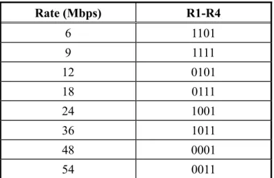
Table 2.3: Contents of RATE field Rate (Mbps) R1-R4 6 1101 9 1111 12 0101 18 0111 24 1001 36 1011 48 0001 54 0011
Chapter 3
Link Adaptation for IEEE 802.11a
Systems
As mentioned in Section 2.1.2, one of the benefits of the RTS/CTS access method is to increase the system performance by minimizing the amount of time wasted when collisions occur on long data frames. On the other hand, the two additional frames without any payload (RTS and CTS) decrease efficiency. For that reason, the use of the RTS/CTS access method is under the control of the manageable object, RTS_Threshold, which indicates the data length under which the data frames should be sent without RTS/CTS. The data frame size is the only parameter that is used for deciding whether the mechanism is applied [2][3]. But what we are really concerned about is the transmission duration of the data frame not the length. However, the higher the PHY rate, the shorter the transmission time. Therefore, an integrated mechanism, which could consider both the length of the data frame and the used PHY rate, is needed.
In [10], a generic method to analyze the goodput (good throughput, excluding MAC/PHY overheads at MAC layer) performance of the IEEE 802.11a system is presented. Utilizing and extending this goodput analysis, we propose an link adaptation (LA) algorithm which could not only select the transmission rate but also
the MAC mechanism (the basic access method or RTS/CTS access method). In this LA algorithm, besides data payload length, we consider other parameters like the wireless channel condition and number of contending stations to select the best combination of the MAC mechanism and PHY mode.
In this chapter, we will analyze the collision probability of the IEEE 802.11a system in Section 3.1. Some detailed MAC and PHY characteristics including MAC/PHY overheads and error performance of IEEE 802.11a PHY modes will be introduced in Section 3.2 and 3.3, respectively. Section 3.4 shows the analysis of effective goodput of the 802.11a system. Based on the results obtained in Section3.4, a LA algorithm is proposed in Section 3.5 and evaluated in Section 3.6.
3.1 Collision
Probability
In [2][21], Markov process is used to analyze the performance of the 802.11 system and show that the Markov chain analysis method is suitable for examining the performance of the IEEE 802.11 system, which captures the effect of the CW value and binary slotted exponential backoff procedure used by DCF in IEEE 802.11. The Markov model in [22] can be regarded as an extension of the model in [2][21], which takes the retransmission limit of MAC frames into account, therefore a more exact model is proposed. With this Markov model, the behavior of a station is examined, which we use to get the collision probability p that a transmitted frame collides with another. We put the obtained collision probability in the 802.11a system to the later use for computing the effective goodput.
In this section, the assumptions necessary for the presented analytical framework are as follows:
1. We ignore the effect of frame errors due to bit errors introduced by channel noise since the effect of frame errors is small (shown in later section). Therefore, frames are received in error only when they encounter collisions due to other simultaneous transmissions.
2. No hidden stations and propagation delays are considered.
3. The network consists of a fixed number of contending stations n and every station always has a frame available for transmission (saturated conditions). Moreover being all frames consecutive, each frame needs to wait for a random backoff time before transmitting.
4. The main approximation is that the collision probability of a transmitted frame is constant and independent of the number of retransmission that this frame has experienced in the past.
Let b(t) be the stochastic process representing the backoff window size for a
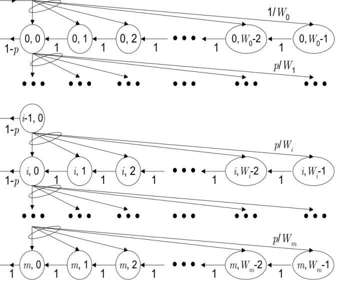
given station at slot time t. A discrete and integer time scale is adopted: t and t+1 correspond to the beginning of two consecutive slot times, and the backoff counter of each station decrements at the beginning of each slot time. Let s(t) be the stochastic process representing the backoff stage (0,…,m) of the station at time t. According to the above assumptions, the bi-dimensional process {s(t), b(t)} is possible to be modeled with the discrete-time Markov chain, which is shown in Figure 3.1.
In IEEE 802.11a PHY, CWmin and CWmax equal to 15 and 1023, respectively (as shown in Table 2.2). Therefore we have
(3.1) ' 2 ' 2 ' i i m i W W i W W i = ≤ = > m m
where i ∈(0,m) is called backoff stage, W=(CWmin+1), and 2
]
m’W=(CWmax+1),
so for IEEE 802.11a PHY, we have m’ = 6. We use m to represent maximum backoff stage. As specified in IEEE 802.11, this value could be larger than m’ and the CW value will be hold after that, which is shown in equation (3.1). In fact, m is the
ShortRetryLimit and equal to 7 according to the standard described in Section 2.1.1.
In this Markov chain, the only non-null one-step transition probabilities are
{
}
[ ]{
}
( ) [{
}
[ ]{
}
0 0 0 0 , | , 1 1 0, 2 , 0, 0, | , 0 1 / 0, 1 , 0, 1 , | 1, 0 / 0, 1 , 1, 0, | , 0 1/ 0, 1 i i i P i k i k k W i m P k i p W k W i m P i k i p W k W i m P k m W k W + = ∈ − ∈ = − ∈ − ∈ − = ∈ − ∈ = ∈ − − (3.2)where we adopt the short notation:
{
1 1, | ,0 0}
{
( 1) 1, ( 1) 1| ( ) 0, ( ) 0}
P i k i k =P s t + =i b t+ =k s t =i b t =k (3.3)
These transition probabilities account, respectively, for: i) the decrements of the backoff timer; ii) after a successful transmission, the backoff timer of the new frame starts from the backoff stage 0, and thus the backoff is initially uniformly chosen in the range (0,W0 -1); iii) when an unsuccessful transmission occurs at backoff stage i-1, the backoff stage increases, and the new initial backoff value is uniformly chosen in the range (0,Wi -1); iv) at the maximum backoff stage, the CW value will be reset if the
transmission is unsuccessful or restart for a new frame if the transmission is successful.
Let b P be the
stationary distribution of the Markov chain. First note that
( ) ( ) { } ( )
(
, limt , , 0, , 0, i 1 i k = →∞ s t =i b t =k i∈ m k ∈ W −)
m (3.4) ,0 1,0 i 0 i b− ⋅ =p b < ≤ithen
(3.5)
,0 i 0,0 0
i
b = p b < ≤ mi
Since the chain is regular, so for each k ∈
(
0,Wi −1)
, it is( ) 1 ,0 ,0 0 , 1,0 1 0 0 m j m i j i k i i p b b i W k b W pb i m − = − − + = − = < ≤
∑
(3.6)With (3.5) and transition in the chain, equation (3.6) can be simplified as
,0 , i i 0 i k i W k b b i W − = ≤ ≤ m (3.7)
Thus, by (3.5) and (3.7), all the value bi,k are expressed as functions of the value b0,0 and collision probability p. Impose the normalization condition for the stationary distribution as follows. 1 1 ,0 ,0 , 0 0 0 0 0 1 1 2 i i W W m m m i i i k i k i k i i W k W b b b W − − = = = = = − + =
∑ ∑
=∑
∑
=∑
i i (3.8)From (3.1), (3.7), and (3.8), b0,0 is finally determined.
( )( ) ( )
(
)
( ) ( )(
)
( )( ) ( )(
)
( ) ( )(
)
( )(
)
1 1 0,0 ' 1 1 ' ' 1 ' 2 1 2 1 ' 1 2 1 1 2 1 2 1 2 1 ' 1 2 1 1 2 1 2 1 2 1 m m m m m m m m p p m m W p p p p b p p m m W p p p p W p p p + + + + + − − − ≤ − − + − − = − − > − − + − − + − − (3.9)As any transmission occurs when the backoff counter is equal to zero, regardless of the backoff stage, the probabilityτthat a station transmits in a randomly chosen slot time can be expressed as 1 ,0 0,0 0 1 1 m m i i p b p τ + = − = = −
∑
b τ (3.10) where b0,0 can be obtained from equation (3.9).unknown. To find the value of p, it is sufficient to note that the probability p that a transmitted packet encounters a collision is the probability that, in a time slot, at least one of the n-1 remaining stations transmit. The fundamental independence assumption given above implies that each transmission sees the system in the same state, i.e., in steady state. At steady state, each remaining station transmits a frame with probability
. This yields τ τ∗ ( ) 1 1 1 n p = − −τ − (3.11)
Therefore, equations (3.10) and (3.11) represent a nonlinear system with the two unknown variables and p, which can be solved by the numerical technique. It is easy to prove that this system has a unique solution. In fact, inverting (3.11), we can obtain τ ( ( )p p)1/(n 1) τ∗ = − (0,1 p ∈
1− −1 . This is a continuous and monotone increasing
function in the range ), that starts from τ∗( )0 =0 and grows up to
( )1 =1 τ( )p
( )p τ
. Equation defined by (3.10) is also continuous in the range .
Moreover, is trivially shown to be a monotone decreasing function. Uniqueness
of the solution is now proven noting that and
(0,1)
p ∈
( )0
τ >τ∗( )0 τ( )1 <τ∗( )1 . Figure
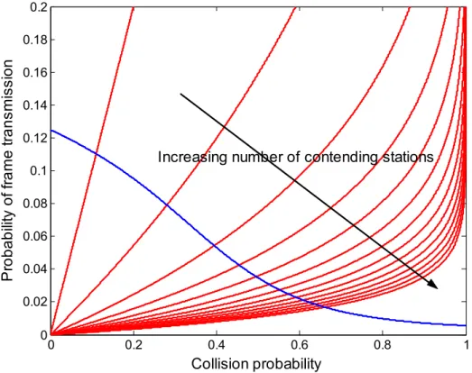
3.2 shows the numerical solutions of both equations with varying values of n, the number of contending stations. For each value of n, the solution yields a unique value for the collision probability p that we will utilize to compute the effective goodput in the later section. The value of the collision probability is sensitive to the number of stations, n. This is shown in Figure 3.2 and Figure 3.3 in which the value of p increases as we increase the number of stations, n. This is an expected result because the number of stations increases, there is more contention among all the stations.
3.2 MAC/PHY
Layer
Overheads
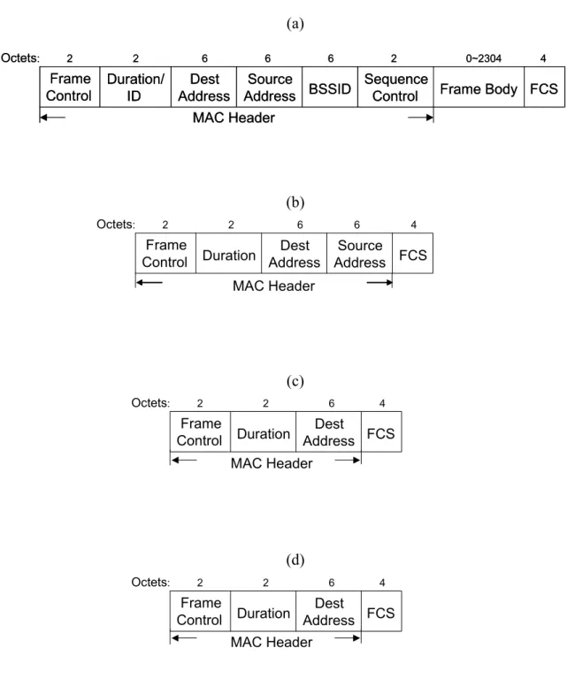
As shown in Figure 3.4(a), in IEEE 802.11 MAC, each MAC data frame, or MPDU, consists of the following components: the MAC header, variable-length information frame body (MAC service data unit, MSDU), and FCS. The MAC overhead due to the MAC header and the FCS is 28 octets in total. Actually, an additional field of Address 4 is used only for the wireless AP-to-AP communication, which is not common, and hence we assume that is not used. Besides, the information frame body (data payload) can be up to 2312 if encryption is used, but we assume that encryption is not used. Figure 3.4(b)~(d) illustrate the frame formats of the RTS, CTS, and ACK frames, which are 20, 14, and 14 octets long respectively.
Review Section 2.2, during the transmission, a PLCP preamble and a PLCP header are added to an MPDU to create a PPDU. The PPDU format of the IEEE 802.11a PHY is shown in Figure 2.4, which includes the PLCP preamble, PLCP header, PSDU (i.e. MPDU conveyed from MAC), tail bits, and pad bits (if necessary). The
PLCP preamble field, with the duration of TPREAMBLE, is composed of 10 repetitions
of a short training signal (0.8 µs) and two repetitions of a long training signal (4 µs). The PLCP header, except the SERVICE field, with the duration of TSIGNAL, constitutes a single OFDM symbol, which is transmitted with the BPSK modulation and rate-1/2 convolutional coding. The six zero tail bits are used to return the convolutional decoder to the zero state and the pad bits are used to make the resulting bit string into a
multiple of OFDM symbols. Each OFDM symbol interval, denoted by TSYM, is 4 µs.
The 16-bit SERVICE field of the PLCP header and MPDU (along with six tail bits and pad bits), represented by DATA, are transmitted at the data rate specified in the RATE field. Table 2.2 lists the related characteristics for IEEE 802.11a PHY.
Note that, while the data frame MPDUs can be transmitted at any supported data rate, all the control frames, including the RTS, CTS, and ACK frames, have to be transmitted at one of the rates in the BSS basic rate set so that they can be understood by all the stations in the same network. BSS basic rate set data rates are preset for all the stations in BSS. {6 Mbps, 12Mbps, 24Mbps} is the set of the IEEE 802.11a mandatory data rates, and it will be assumed to be the BSS basic rate set in our example and simulations. In addition, the RTS and CTS frame will be transmitted at the lowest rate in the BSS basic rate set (6Mbps) while the ACK frame transmitted at the highest rate in the BSS basic rate set that is less than or equal to the rate of the data frame it is acknowledging. For example, if a data frame is transmitted at the rate of 18 Mbps, the corresponding ACK frame will be transmitted at the rate of 12 Mbps.
Based on the above descriptions, to transmit a frame with an l-octet data payload over IEEE 802.11a PHY using the PHY mode m, the transmission duration is
( ) ( ) 28 (16 6)/ 8 ( , ) 30.75 20 4
data PREAMBLE SIGNAL SYM
l T l m T T T BpS m l s s BpS m µ µ + + + = + + ⋅ + = + ⋅ (3.12)
Note that the Bytes-per-Symbol information for the PHY mode m, BpS(m), is given in Table 2.1. Similarly, the transmission duration for a RTS frame and a CTS frame are
( ) ( ) 20 16 6 8 1 22.75 20 4 52 3
rts PREAMBLE SIGNAL SYM
T T T T BpS s s s µ µ µ + + = + + ⋅ = + ⋅ = (3.13) and
( ) ( ) 14 16 6 8 1 16.75 20 4 44 3
cts PREAMBLE SIGNAL SYM
T T T T BpS s s s µ µ µ + + = + + ⋅ = + ⋅ = (3.14)
respectively. Note that the transmission rate of RTS and CTS is the lowest BSS basic rate, 6Mbps, i.e. PHY mode 1. And the transmission duration for an ACK frame using the PHY mode m’ is
( ) ( ) ( ) ( ) 14 16 6 8 ' ' 16.75 20 4 '
ack PREAMBLE SIGNAL SYM
T m T T T BpS m s s BpS m µ µ + + = + + ⋅ = + ⋅ (3.15)
The relation between m and m’ is discussed above.
3.3
Error Performance of PHY Modes
3.3.1 Bit Error Probability
The symbol error probability (SER) for an M-ary (M=4, 16, 64) QAM with the average received SNR per symbol, γ, can be calculated by [23]
( ) 1 1 ( )2 M M P γ = − − P γ (3.16) where ( ) 2 1 1 3 1 M P Q M M γ = ⋅ − ⋅ − ⋅γ (3.17)
is the SER for the M −ary pulse amplitude modulation (PAM).
{ }
_ 2 _ 2 2 1 1 0 0 _ _ c c N data N data k k s k k c k c h E h E x N data N N N data γ = = ⋅ ⋅ = = ⋅∑
∑
(3.18) The Q-function is defined as( ) 1 2 2 2 y x Q x e dy π ∞ − =
∫
(3.19)With a Gray coding, the bit error probability (BER) for an M-ary QAM can be approximated by ( )( ) ( ) 2 1 log M b P M γ ≈ ⋅PM γ (3.20)
Note that the 4-ary QAM and QPSK modulation are identical. For the BPSK modulation, BER is the same as SER, which is given by
( )2
( )
( )
(
2 2 b P γ =P γ =Q γ)
m u γ P γ (3.21) Obviously, the error performance of a modulation scheme varies with differentreceived SNR values.
3.3.2 Frame Error Probability
In [24], an upper bound was given on the frame error probability under the assumption of binary convolutional coding and hard-decision Viterbi decoding with independent errors at the channel input. For an l-octet long frame to be transmitted using the PHY mode m, this bound is
(3.22)
( ), 1 1 ( )8l
m e
P l γ ≤ − − P
where the union boundPm( )of the first-event error probability is given by
u γ (3.23) ( ) ( ) free m u d d d d P γ ∞ a = =