國
立
交
通
大
學
網路工程研究所
碩
士
論
文
影 像 輔 助 之 協 同 式 車 輛 定 位 系 統
Video-Assisted Inter-Vehicle Positioning
研 究 生:方唯義
指導教授:簡榮宏 博士
影 像 輔 助 之 協 同 式 車 輛 定 位 系 統
Video-Assisted Inter-Vehicle Positioning
研 究 生:方唯義 Student:Wai-Yee Fong
指導教授:簡榮宏博士 Advisor:Dr. Rong-Hong Jan
國 立 交 通 大 學
網 路 工 程 研 究 所
碩 士 論 文
A Thesis
Submitted to Institute of Network Engineering College of Computer Science
National Chiao Tung University in partial Fulfillment of the Requirements
for the Degree of Master
in
Computer Science
July 2012
Hsinchu, Taiwan, Republic of China
I
影 像 輔 助 之 協 同 式 車 輛 定 位 系 統
研究生:方唯義
指導教授:簡榮宏 博士
國立交通大學 網路工程研究所
摘要
智慧型交通運輸系統(Intelligent Transportation System, ITS)在車載環境中提 供了各種不同的服務。許多的ITS應用都需要利用到車輛準確的位置資訊。然而 目前的一些定位方法無法擁有充足的準確性或是受限於佈建成本,並不能完全適 用於目前的車載環境中。故在此論文中,我們提出了影像輔助之協同式車輛定位 系統 (Video-Assisted Inter-Vehicle Positioning, VIP)。此系統整合了GPS接收器與 行車紀錄器透過影像處理所摘取的感測資料,並經由車間通訊來交換這些資訊以 提升定位的準確性。在此系統中,我們假設每台車輛都裝設GPS接收器以及 WAVE/DSRC通訊模組;並且有部分的車輛裝設了行車紀錄器。裝設行車紀錄器 的車輛可以透過影像辨識出的車道別,以及透過電子地圖找出GPS位置對應的車 道別來驗證GPS位置的誤差程度。在協同式定位的過程中,這些資訊與附近車輛 進行交換,區別出車輛GPS位置的權重並對自己的GPS位置進行修正。模擬的結 果顯示我們的方法在一半的車輛裝設行車紀錄器的情形下,車輛位置的準確性即 可達到百分之十至三十的提升。而在所有車輛都裝設了行車紀錄器的情形下,準 確性提升了百分之三十至四十(修正到三公尺內)。
II
Video-Assisted Inter-Vehicle Positioning
Student: Wai-Yee Fong Advisor: Rong-Hong Jan
Institute of Network Engineering National Chiao Tung University
Abstract
Intelligent Transportation System (ITS) provides various services for vehicular environments. Most of the ITS applications require accuracy position of vehicle to be developed. However, the current positioning techniques and devices may not satisfy the accuracy. In this thesis, we present a Video-Assisted Inter-Vehicle Positioning (VIP) system. The system integrates sensed data extracted from GPS receiver and driving video logger with image processing techniques, and then the sensed data is exchanged to nearby vehicles for improving the accuracy of cooperative positioning. In our system, each vehicle is equipped with a GPS receiver and WAVE/DSRC equipment, and some vehicles are equipped with driving video logger, called fully
equipped vehicle. Each fully equipped vehicle will assess the difference between the
lane recognized by the image processing module and the lane is referred to digital map module to validate the accuracy of its GPS position. Then, these information will be exchanged among vehicles to differentiate the weights of received positions during the cooperative positioning process. Simulation results show that our approach can achieve 10~30 percent of improvement in the position accuracy when only half of vehicles were fully equipped, and improve the accuracy by factor of 30~40 percent (within 3m) if all vehicles were fully equipped.
III
誌謝
在此我要特別感謝指導教授簡榮宏博士,在我的研究生生涯中給予關切的指 導。不論是在課業、研究、計畫以及生涯規劃上老師都給予了不少的引導與關懷。 並且在進行學術研究的過程中提出了不少建議,得以在多次的方法設計與實驗中 完成我的碩士研究。同時,學生也很感謝口試委員交通大學資訊學院陳健教授、 易志偉教授以及工研院資通所曾蕙如博士對本碩士論文不吝給予指正與建議,使 本論文更臻完善。並感謝陳健教授以及安凱學長與我不斷的討論改進方法,致使 我的碩士研究能夠更加完善與完整。 在兩年的研究生活中,感謝計算機網路實驗室的學長姐(安凱、蕙如、嘉泰、 家瑋、鈺翔、欣雅、冠傑、良叡)、同學(慈麟、紹閔、曰慈、怡萱)以及學弟(和 家、瑋劭、秉琨、景祥)們,在課業與生活上的共同努力、互助與關懷,使我獲 益良多。也感謝家人與朋友所付出的關懷與鼓勵,使我能夠堅持完成研究。在此 將本文獻給所有身邊的人,並與大家分享完成論文的喜悅。IV
Contents
Abstract (in Chinese) ...I Abstract (in English) ...II Acknowledgements ...III Contents ...IV List of Figures ...VI List of Tables ...VII
Chapter 1 Introduction ...1
Chapter 2 Related Work ...6
Chapter 3 System Architecture and Relevant Techniques ...9
3.1. System Architecture ... 9
3.2. Inter-Vehicle Communications ... 11
3.3. Lane Recognition Techniques ... 12
3.4. Lane Matching Techniques ... 12
V
Chapter 4 Video-Assisted Inter-Vehicle Positioning (VIP) System ...14
4.1. Assumptions & Symbols ... 14
4.2. System Flow... 15
4.3. Sensing Stage ... 17
4.4. Sharing Stage ... 17
4.5. Estimation Stage ... 18
4.6. VIP System ... 19
Chapter 5 Simulation Results and Analysis ...24
5.1. Simulation Environment ... 24
5.2. Simulation Results ... 26
Chapter 6 Conclusion ...35
VI
List of Figures
Figure 1-1 : Example of direction shift effect ... 4
Figure 3-1 : System architecture ... 10
Figure 3-2 : Architecture of vehicular network ... 11
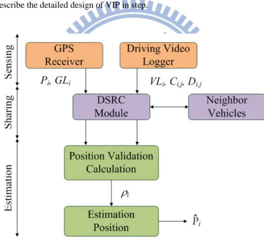
Figure 4-1 : Block diagram of proposed system ... 16
Figure 4-2 : Procedure of VIP ... 20
Figure 4-3 : Example of VIP ... 22
Figure 5-1 : Simulation roadway setup ... 25
Figure 5-2 : Comparison the lane discrimination with GPS lane and video lane ... 26
Figure 5-3 : RMSE with different values of the scaling factor and GPS error ... 27
Figure 5-4 : Distribution of position validation under different scaling factor ... 28
Figure 5-5 : Improvement rate with scaling factor and GPS error ... 28
Figure 5-6 : RMSE with different ratio of fully equipped vehicles ... 29
Figure 5-7 : Measure the ratio of correction vehicle with different ratio of fully equipped vehicles ... 30
Figure 5-8 : RMSE with vehicle flow rates ... 31
Figure 5-9 : RMSE with sensing ranges ... 32
Figure 5-10 : RMSE with sensing angles ... 32
Figure 5-11 : RMSE with different number of lanes ... 33
VII
List of Tables
Table 1.1 : The requirement of positioning accuracy in some ITS applications ... 3
Table 2.1 : Comparison of various positioning techniques ... 7
Table 4.1 : List of symbols ... 15
1
Chapter 1
Introduction
Intelligent Transportation System (ITS) provides various services for vehicular environments. Safety service is one of the most important topics in ITS. It includes many applications, such as lane departure warning, accident warning alarm, collision avoidance and etc.
Vehicular Ad-Hoc Networks (VANETs) is an emerging technique for ITS. It supports inter-vehicle communications [1] in a wireless medium that included vehicle-to-vehicle (V2V) and vehicle-to-infrastructure (V2I) modes to collect and share driving information for achieving better real time service proving. For providing Wireless Access in Vehicular Environments (WAVE) that IEEE802.11p [2][3][4] and IEEE1609 [4-11] protocol has been proposed. The dedicated frequency band of 75MHZ has been designed for vehicle use in a short range, and the set of emerging techniques for ITS communications are called Dedicated Short Range Communications (DSRC). The WAVE/DSRC represents the set of techniques compose of IEEE802.11p and IEEE1609 standards. It makes data transfer more reliable, and provides a low delay and stable environment for wireless communications in a short range.
VANETs provide safety and non-safety applications [12]. Safety applications are designed for improving driving safety, such as Emergency Warning Message (EWM)
2
[13][14][16], Cooperative Collision Avoidance (CCA) [15][16] applications and etc. These applications much rely on a high accuracy positioning system [20] and lower delay. Such in CCA application, the rear vehicles need much precise positions to determine whether car accidence occurred in the front vehicle for preventing chain-car collision [15][16]. Providing accurate positions also help emergent alert system to precisely discriminate the margins of endanger areas so as to reduce the overhead of broadcasting emergency messages [13][15].
Non-safety applications include vehicular traffic coordination, road traffic management and comfort applications. These applications were designed to assist driver, improve traffic flow, or travel more comfortable. Om the other hands, traffic monitoring [17], intersection assistance [18] and electronic toll collection (ETC) [19] are some examples of non-safety applications. The traffic monitoring application is designed for providing traffic relevant traffic information collected by probe vehicles and vehicle navigation system constructs a traveling path between two points need more accurate to navigate the driver correctly.
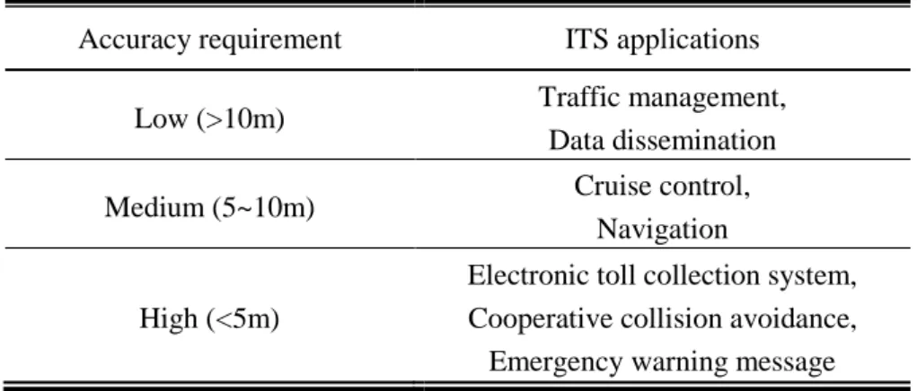
Global Positioning System (GPS) has been widely used to obtain position [21]. A vehicle can acquire its geographic position from a GPS receiver. However, the accuracy of positions could be affected by many factors, such as satellite noise, signal blocking, multipath signal and etc. Regular GPS can provide with 5 to 15 meters localization accuracy in different environments. As shown in Table 1.1, the accuracy of positioning is not enough for most of services in ITS [12-20].
3
Table 1.1 : The requirement of positioning accuracy in some ITS applications
Accuracy requirement ITS applications
Low (>10m) Traffic management,
Data dissemination
Medium (5~10m) Cruise control,
Navigation
High (<5m)
Electronic toll collection system, Cooperative collision avoidance, Emergency warning message
To provide better positioning ability in vehicular environments, various techniques for improving localization were also proposed, e.g. differential GPS (DGPS) [22][23], dead reckoning (DR) [24], data fusion techniques (e.g. kalman filter and particle filter [25] ) and etc. However, these techniques have their limitation, they maybe require expensive cost, computation complexity, or cannot achieve satisfiable accuracy in vehicular environments.
Combination of localization and V2V communications is a solution to improve the positioning accuracy that is called cooperative positioning [26][27][28]. In the concept of cooperative positioning, vehicles share their driving data like speed, direction and location with V2V communications. Besides, vehicles should obtain inter-vehicle distances with ranging methods [35][36] (e.g., received signal strength indictor (RSSI [38]), time of arrival (TOA), angle of arrival (AOA) and etc.), and use these information to correct position errors.
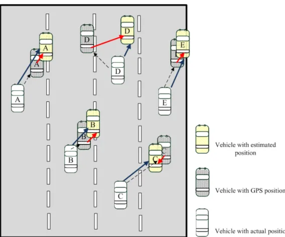
However, the directional shift effect will cause inaccurate positioning in some cooperative positioning approaches, such as solving least square method, it cannot find out the more accurate GPS positions as reference points. Given an example in Figure 1.1, most of vehicles have an inaccurate GPS position that is in northeast of its actual position. The corrected positions are concentrating to the northeast, and cannot improve the accuracy of
4
GPS position. In this situation, the corrected result shows the estimated position will shift to the same direction because the GPS errors are accumulated in the northeast. We can design an algorithm to find out the more accurate reference GPS position to remove the directional shift effect problem. Besides, traditional ranging methods use radio to measure inter vehicle distances, the signal propagation of these method will be affect by multipath and shadowing effects, and then cause positioning inaccurate.
Figure 1-1 : Example of direction shift effect
Recently, video sensing techniques are widely used in vehicular environments. In the imaging processing domains, many researches contribute to provide safety functions for ITS applications, such as automatic number plate recognition (ANPR) [41][42], lane detection
5
and tracking [31][32], vehicle tracking [43], inter-vehicle distance measuring [44][45] and etc. Above functions can be realized in real time by advanced image processing embedded system nowadays, and the errors of processing is small enough that can be eliminated in a short range. Also driving video logger price down so it is popular for installing driving video logger in a vehicle, and more advanced, the driving video logger may have some image processing abilities. It can provide more information that traditional cannot acquire, such as license plates, relative positions, vehicle behaviors and driving events.
In this thesis, we propose a Video-Assisted Inter-Vehicle Positioning (VIP) system. The system integrates sensed data extracted from driving video logger with image processing and share to information among vehicles to improve the accuracy of cooperative positioning. In our system, each vehicle is equipped with a GPS receiver and WAVE/DSRC equipment, and some vehicles are equipped with a driving video logger, called fully equipped vehicles. Each fully equipped vehicle will assess the difference between the lane recognized by the image processor and the lane referred from geographic position to validate the accuracy of its GPS position. Then, the validated values will be exchanged among vehicles by the communication module to differentiate the weights of received positions during the cooperative position process. Simulation results shown that our approach can achieve 25% of improvement in the position accuracy when only half of vehicles were fully equipped, and improve the accuracy by factor of 40% (within 3m) if all vehicles were fully equipped.
The rest of this thesis is organized as followings. Chapter 2, we review the different positioning techniques and related works about cooperative positioning in vehicular environment. In Chapter 3, we show the system architecture of VIP and survey of relevant techniques. In Chapter 4, the assumptions, notations and detailed design of VIP system are presented. Experimental results of proposed approach are given in Chapter 5. Finally, conclusion remarks with this thesis are given in Chapter 6.
6
Chapter 2
Related Work
Localization vehicles in vehicular environment needs highly accuracy for supporting safety applications, in many researches that used GPS as vehicle positioning modules, and they concentrate to arise the accuracy and performance of positioning. A variety of positioning techniques were proposed in the literature.
In Differential GPS (DGPS) technique [22][23], vehicles can obtain correction packets from Reference Stations (RS). Vehicles use these packets to revise their position. The concept of DGPS is the correlated error of GPS can be removed by differential calculation in an area, RS computes the differential with already known exactly position and position obtained by GPS receiver from the signals of satellites, and then broadcast to around receivers. Under better conditions, the accuracy of vehicle positioning with DGPS can below one meter. However, it needs expensive cost to fill reference stations in a large area, and positioning error produced by signal blocking with other obstructs, some researches proposed low-cost DGPS systems to reduce construction cost and positioning error [29][30].
Dead Reckoning (DR) [24] is used with bad GPS signal or unavailable in general, sometimes used to correct position. With this technique, vehicle estimate the next position by using driving data (e.g. speed, direction, acceleration) obtained from inertia measurement
7
unit (IMU) or inertial navigation systems (INS). The positioning error accumulates when driving until to get a new position.
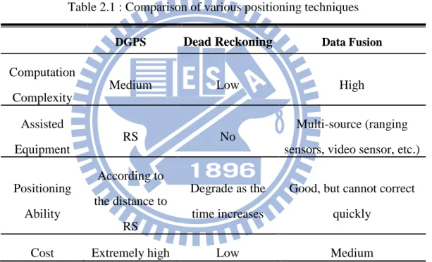
Data fusion techniques used in vehicle positioning such as Kalman Filters and Particle Filters [25] which are recursive operations for position estimation. Combination of IMU, INS and driving data of other vehicles exchanging with V2V communications as information sources can used to remove the errors of positioning. These filtering techniques provide optimal model fusion the data measured by multiple sources can improve the positioning accuracy. Table 2.1 summarizes the position techniques above mentioned.
Table 2.1 : Comparison of various positioning techniques
DGPS Dead Reckoning Data Fusion
Computation Complexity
Medium Low High
Assisted Equipment
RS No
Multi-source (ranging sensors, video sensor, etc.)
Positioning Ability According to the distance to RS Degrade as the time increases
Good, but cannot correct quickly
Cost Extremely high Low Medium
Cooperative positioning has proposed for integration of positioning techniques and V2V communications, most of proposed methods use ranging methods [35][36] such RSSI [38], TOA and Doppler shift to obtain inter vehicle distance between nearby vehicles, vehicles share the distance and absolute or relative position to neighbor vehicles with WAVE/DSRC equipment, and then these use weighted, matrix calculation or filtering methods to estimate position.
8
In [26], the authors assumed vehicles can measure inter-vehicle distances between neighbor vehicles by RSSI techniques. The measured distance and vehicle’s position were broadcasted, and then received vehicle can estimate its position with least square method for solving the minimized the residual distances between its original position and measured distances. In [27] , Doppler shift was used to measure the relative mobility with opposite direction vehicles, and it can be extracted with signals. Each vehicle broadcasts its observed speed, position and relative mobility to opposite direction vehicles. Above mentioned information will feed to extended kalman filter (EKF) for estimating position. In [28] , each vehicle uses ranging sensor to measures relative angles and distances between vehicles. And will be broadcasted to neighbor vehicles. Vehicles use the information to estimate its position and reserve the estimation position as position candidates for future calculates. The position calculation is referred to position candidates’ freshness, error distribution of measured GPS and velocities.
Above vehicle positioning methods can improve the accuracy, however, different algorithm have their problems such as expensive implementation cost, limitation, computation complexity, and other errors generated by signal multipath and blocking , these problems that the method hard to implement or lack of accuracy.
9
Chapter 3
System Architecture and Relevant
Techniques
In this chapter, we provide an introduction for our system architecture and relevant techniques.
3.1. System Architecture
The system architecture as shown in Figure 3.1, each vehicle acquires its geographic position with the GPS receiver, and the position is used to share with neighboring vehicles for estimating position. Also, each vehicle is equipped with a WAVE/DSRC module for exchanging position and related data with wireless media. Moreover, some vehicles are equipped with a driving video logger, called fully equipped vehicles. The driving video logger integrates the image processing functions such as ANPR, vehicle and lane detection/tracking. The recognized driving elements we called sensed data may help vehicles to improve positioning accuracy. An On-Board Unit (OBU) device has wireless and wired communication capabilities for connecting processing units in vehicles. This operation of system as shown in follows. First, each vehicle receives raw geographic position from
10
several satellites via its GPS receiver, and the GPS position can be matched with a digital map module to obtain a referred lane index, this referred lane index is used to verify the accuracy of GPS position in the later calculation. The fully equipped vehicle equipped with driving video logger, it scans the front vehicles and lanes then sends the sensing image to video processor for identifying their license plates, relative distances, lane discriminations and absolute lane index. Each vehicle broadcast its sensed data to neighbor vehicles via DSRC module. After finish the data exchanging, vehicle compares the referred lane of GPS position matching with digital map and absolute lane recognized by image processing module to validate its and the received GPS positions. The validating value can be used to access the accuracy of position and calculate a corrected position.
Figure 3-1 : System architecture
From the above illustration, we can see that our system involve the inter-vehicle communications, lane recognition, lane matching and ranging techniques. In the following sections, we survey the state-of-the art of the above techniques, respectively.
11
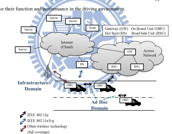
3.2. Inter-Vehicle Communications
According to the advance with wireless networks and information technologies, as shown in Figure 3.2, the vehicular networks [12] have been proposed for providing moving vehicles that equipped with an On-Board Unit (OBU) can communicate with other vehicle and road side units (RSUs) in wireless. The 75MHZ DSRC spectrum in the 5.9GHZ band was allocated by the United States Federal Communications Commission (FCC), and it consists one control channel (CCH) and six service channels (SCHs). The channels are provided to transfer safety and non-safety messages for ITS applications. DSRC technique provides vehicles can communication in a low delay and reliable environment, it makes different applications can achieve their function and performance in the driving environment.
12
3.3. Lane Recognition Techniques
Lane recognition techniques use the image processing to detect and track lane when a vehicle is driving, the lane information can be used in a ITS application for providing safety driving. Some researches proposed vision-based lane recognition algorithm, in [31] presented a road-marking detection system. This system can operate robustly and real-time approach in urban streets. It is processing on taking a top-view of the image of camera. It first transforms the input image into top-view image with Inverse Perspective Mapping (IPM) that lanes will become parallel lines. And then they detect lanes with RANSAC line fitting and Spline Fitting. With the simulation results show the detection of multi-lane in efficiently and correctly. In [32], the authors propose a novel “video-based lane estimation and tracking” (VioLET) system. This system can detect lane-marking robustly with camera as video input in different conditions. They models vehicle and road dynamics and update with using a Kalman filter. And then the steerable filters are used to classify and detect road-marking. The simulation results of this paper have shown the system can tracking various road-marking with low error under varying road conditions. Above researches have shown the lane detection and tracking can be achieved in real-time with low error in the vehicular environments
3.4. Lane Matching Techniques
Map-matching algorithm is used to identify the correct road segment which vehicle is travelling and determine the location on the segment [33]. This technique integrates the multi-source such as GPS, INS and road network database for providing the correct lane information which vehicle located. The lane index of vehicle can be obtained by the map-matching algorithm, and the lane information can provide vehicle navigation,
13
positioning and data collection functions. In [33], the authors proposed the map-matching algorithm to determine vehicle on which road segment. It integrates the sensed data like GPS position and direction extracted from GPS and DR modules to find the closest node on the map. In [34], a vehicle lane determining system is proposed. This system integrates an onboard DGPS receiver, a lane-level digital roadway database, a developed lane-matching algorithm, and a real-time vehicle location display. A vehicle in this system sends its position, speed and vehicle status data to the base station, the vehicle lane map-matching process will be operated to find the vehicle on which lane. The lane map-matching process uses the continued vehicle trajectory to find the candidate of lane.
3.5. Distance (Ranging) Techniques
To measure the distance in vehicular environments can use the ranging techniques [35][36] such as Received Signal Strength Indication (RSSI [38]), Time Of Arrival (TOA), Time Difference Of Arrival (TDOA) and Angle-of-Arrival (AOA). RSSI technique estimates the distance with signal strength measurement received by antennas [37]. TOA and TDOA both use the signal propagation time to measure the distance with known signal propagation speed. TOA can directly calculate the time of arrival with signal propagation between two nodes, and the synchronization accuracy will affect the performance. On the other hand, TDOA measures the difference of arrival time of multi signal sources. It can eliminate the clock drift problem of TOA and do not require synchronizing. The AOA technique measures the angles with received signal to estimates the desired target by using the directive antennas or antenna arrays. The performance degrades when distance of nodes increases and the accuracy of AOA are easily effect by signal multipath.
14
Chapter 4
Video-Assisted Inter-Vehicle
Positioning (VIP) System
In this chapter, we present the Video-assisted Inter-Vehicle Positioning (VIP) system. We first make some assumptions and the used symbols of our system. Then, the detailed design of our proposed system will be presented in step.
4.1. Assumptions & Symbols
First, we assume that GPS clock is synchronized among vehicles. And the driving video logger is able to recognize precise information about the license plates, relative positions, lane indices in a reasonable range, e.g. 50 meters with 90 angle width. The license plate of vehicle that is recognized by logger can be used to identify different vehicles. The lane index of GPS position can be matched with digital map, and use this information to decide weight of position. We also assume the communication and image processing tine are relatively small or negligible with respective to the update interval of GPS positions, e.g. 1 second.
Table 4.1 lists the notations and symbols used throughout this thesis. For each vehicle
15
identify a lane index of Vi called GPS lane (GLi). At the same time, the lane of Vi sensed by driving video logger is video lane (VLi), and the coordination and lane discrimination between Vi and a sensed vehicle Vj defined as Ci,j and Di,j. After the sensed data exchanged, the set of Vi’s neighbor will be saved as Ni, and a position validation of Pi used to weight Pi is ρi. Finally, the estimated position Pi of vehicle Vi can be calculated.
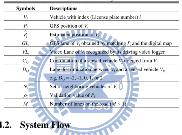
Table 4.1 : List of symbols
Symbols Descriptions
Vi Vehicle with index (License plate number) i
Pi GPS position of Vi
i
P Estimated position of Vi
GLi GPS lane of Vi obtained by matching Pi and the digital map
VLi Video Lane of Vi recognized by its driving video logger
Ci,j Coordination of a sensed vehicle Vj oriented from Vi
Di,j Lane discrimination between Vi and a sensed vehicle Vj,
e.g, Di,j = -2, -1, 0, 1, or 2
Ni Set of neighboring vehicles of Vi
ρi Validation value of Pi
M Number of lanes on the road (M > 1)
4.2. System Flow
The block diagram of proposed system has shown in Figure 4.1. In our system, our goal is to find the better positions between neighbor vehicles to estimate position, so we compare the value of different lane indexes obtained from GPS position and driving video logger in this algorithm. The algorithm consists of three main stages: sensing stage, sharing stage and estimation stage. In the beginning of this system, each vehicle extracts its sensed data from the GPS receiver and the driving video logger. Then, vehicle broadcasts its sensed data to neighbor vehicles. After received the sent data, vehicle uses the lane information to calculate
16
the position validation of neighbor vehicles. Finally, vehicle estimates its position according the GPS positions, relative positions and position validations between neighbors.
The goal of this thesis is to improve the accuracy of vehicle positioning, we want to assign a high weight value on the better GPS position, and otherwise the weight should be approached to 0. With this weighted method, the estimation position which calculated from high weight position should be closed to the real position. Our approach wants to differentiate the reliable of position. We compare the lane of GPS position matching with digital map and the lane recognition with driving video logger. In the following sections, we will describe the detailed design of VIP in step.
17
4.3. Sensing Stage
In the sensing stage, sensed data is used to estimate the position of vehicle for estimating position. Each vehicle Vi retrieves its GPS position Pi from GPS receiver first, and matches Pi with the digital map to obtain the corresponding GLi. If a vehicle Vi is fully equipped, it further uses its driving video logger to recognize the sensed data with the image processing functions in the scanning area. The sensed data contains the license plate number as an unique identifier for each front vehicles, as well as the relative position Ci,j, lane discrimination Di,j and the absolution lane index VLi. The Ci,j can be represented as the vector [x,y]T, where x and y, respectively the vertical and horizontal coordination oriented from Vi to
Vj, and we set a Cj,i = −Ci j, for later position calculation. The lane discrimination Di,j
between Vi and a sensed vehicle Vj is given by one of the values in [−(M – 1), …, −1, 0, 1, …, M – 1], it is provided to a vehicle which is not fully equipped to calculate and update its VLj value. The absolute lane index VLi can be obtained from several of lane recognition or tracking algorithms, which is used to determine the validated values of position. Besides, each vehicle Vi keep track a set Ni of neighboring vehicles what have video sensed data related to itself. In this stage, Ni contains all of the front vehicles recognized form the scanned image, If Vi is not a fully equipped vehicle, Ni is temporarily an empty set thus far.
4.4. Sharing Stage
Since the scanning area of a driving video logger is restricted to a limited angle width (typically from 90 to 150 degrees), each vehicle should share its information with other vehicles to create a more comprehensive view of the surrounding area. In this stage, each vehicle Vi broadcasts a message, containing its Pi and GLi, via the WAVE/DSRC module. If vehicle Vi is fully equipped, the message further contains VLi and all Ci,j’sand Di,j’s of
18 vehicles recognized in the previous stage, i.e. Vj ∈ Ni,
Once vehicle Vi received a message from another vehicle Vj, it checks whether Cj,i is in the message or already being stored in Vi, if it is, Vj is merged into the neighbor set Ni with Ni
= Ni∪ {Vj}, and all related information in this message Pj, GLj, VLj and Cj,i, are stored in
Vi’s memory. Note that if there is no information regarding Cj,i, the information will not be kept, because Vi no clue for inferring a reference position from Pj.
On the other hand, if Vi have not yet known its video lane VLi, i.e. Vi is not fully equipped, it can indirectly obtain this value from one of the fully equipped vehicle Vj that scanned itself, as follows:
,
i j j i
VL =VL +D (1)
That is, if Vi is in the scanning area of some fully equipped vehicle Vj behind it, it can infer its VLi from VLj by shelving Dj,i lane(s).
4.5. Estimation Stage
In the estimation stage, our system validates the accuracy of received GPS positions and estimates a corrected position in accordance with the validating values. Considering a vehicle Vi, for each neighboring vehicle Vj (Vj∈Ni), it validates the accuracy of position Pj by the following equation:
1 1 j j j GL VL M ρ = − − − (2)
In this equation, M represents the number of lanes and M > 1. This equation transforms the difference between the GPS lane GLj and video lane VLj into a validate value ρj between 0 and 1. Note that the calculation of ρj cannot be done in prior by vehicle Vj, because Vj could be a non-fully equipped vehicle. In this case, vehicle Vj has no way to obtain its VLj before
19
receiving any message from other vehicle, and the value of Vj was recognized by Vi. Let P denote a reference position of Vi j, i estimated from Pj, i.e.
i j, j j i,
P =P +C . The corrected position P is calculated as follows: i
{ } , { } , j i i j i i i j V N V j i V N V j P P α α ρ ρ ∈ + ∈ + =
∑
∑
(3)where α > . The corrected position 0 P is the average of all inference positions estimated i
form vehicles in Ni and Vi itself. The validation value ρj gives different weight to each inference position P . An accurate GPS position Pi j, j usually has a small (or no) difference between its GPS lane GLj and the lane VLj recognized by driving video logger, and thus, we give the corresponding reference position P a larger weight, i.e. i j, ρj in the correction. Besides, the parameter α is a scaling factor. Given a larger value of α will magnify the different between a small and a large validating values. As shown in the next chapter, we found that by adequately setting α there is additional 5 percent of improvement in accuracy.
4.6. VIP System
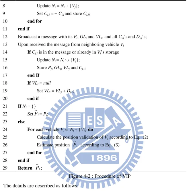
In this section, we show the procedure of VIP system in the following Figure 4.2.
Produce of each vehicle Vi
Initialize: Ni = ; VLi = null;
1 Obtains the position Pi from the GPS receiver;
2 Match Pi with the digital map to find the geographic lane GLi;
3 If Vi is a fully equipped vehicle
4 Capture an image from its driving video logger; 5 Recognize the video lane VLi from the image;
6 For each vehicle Vj recognized from the image do
20 8 Update Ni = Ni + {Vj};
9 Set Cj,i = − Ci,j and store Cj,i;
10 end for
11 end if
12 Broadcast a message with its Pi, GLi and VLi, and all Ci,j’sand Di,j’s;
13 Upon received the message from neighboring vehicle Vj
14 If Cj,i is in the message or already in Vi’s storage
15 Update Ni = Ni ∪ {Vj};
16 Store Pj, GLj, VLj and Cj,i;
17 end If 18 If VLi = null 19 Set VLi = VLj + Dj,i; 20 end if 21 If Ni = {} 22 SetPi= Pi; 23 else
24 For each vehicle Vj ∈ Ni + {Vi} do
25 Calculate the position validation of Vj according to Eq. (2)
26 Estimate position Pi according to Eq. (3)
27 end for
28 end if
29 Return Pi;
Figure 4-2 : Procedure of VIP The details are described as follows:
Line 1: Vi obtains its geographic position Pi with a GPS receiver;
Line 2: Obtain the GPS lane GLi by matching its Pi with the digital map;
Lines 3~5: If Vi is a fully equipped vehicle, it start to capture an image from its driving video logger. It recognizes the video lane VLi from the image with image processing functions;
21
coordination Ci,j and lane discrimination Di,j between Vi and any front vehicle Vj in its sensing area should recorded, and then add Vj into the set Ni of Vi’s neighboring vehicles;
Line 12: If Vi is fully equipped, itbroadcasts its Pi, GLi and VLi, and all Ci,j’sand Di,j’s via WAVE/DSRC module. Else it just broadcasts its Pi and GLi;
Line 13: Upon received the message from neighboring vehicle Vj, Vi does follows actions in lines 14~20;
Lines 14~17: If Cj,i is in the message or already in Vi’s storage, it means the one of Vi and Vj can sense the other one. First, Vi updates its set of neighboring vehicles Ni by Ni = Ni ∪ {Vj}, and then stores Pj, GLj, VLj and Cj,i to its storage for later use;
Lines 18~20: If Vi is not fully equipped, it must calculate its video lane VLi byVLi = VLj +
Dj,i according the received message;
Lines 21~22: If the set of neighboring vehicles Ni = {}, there are not any vehicles nearby Vi, and Vi cannot correct its Pi, and set P = Pi i;
Lines 23~24: If the set of neighboring vehicles Ni is not empty, for each vehicle Vj ∈ Ni + {Vi} does the follows actions in lines 25~26;
Line 25: It calculates the position validation of Vj according to Eq. (2). The validations of vehicle’s position are calculated according to the lane difference of their GL and VL. The lower difference will lead to higher weight for reference position;
Line 26: Vi estimates its position P according to Eq. (3). The estimated equation is i
composed of the reference positions and the validating value that calculated in line 25; Line 29: Return the estimated position P . i
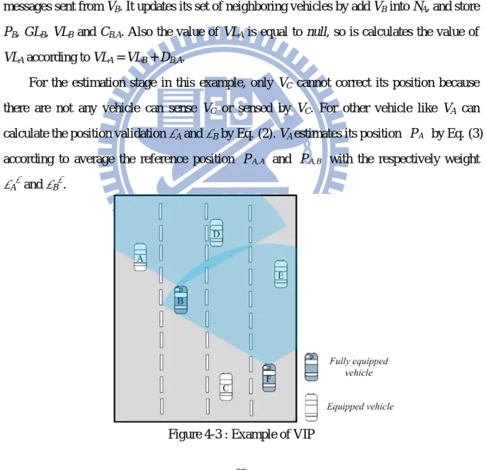
For above procedure, we give a simple example in follows. In Figure 4.3, vehicle VB and VF are fully equipped vehicles, and other vehicles are not fully equipped vehicles. In this example, for the sensing stage vehicle VA, VB, …, VF retrieves their GPS position PA, PB, …,
22
PF with a GPS receiver. And then a fully equipped vehicle VB senses VA and VD then extracts
VLB = 2, CB,A, CB,D, DB,A = -1 and DB,D = 1 with its driving video logger, and fully equipped vehicle VF also senses VB and VE.
In the sharing stage, for the fully equipped vehicle VB and VF, they broadcast their sensed P, GL and VL, and all C’sand D’s via WAVE/DSRC module. Vehicles VA, VC and VD are not fully equipped, and they broadcast their P, GL to neighboring vehicles. In this example, upon VA received the message from neighboring vehicle VB, it finds CB,A is in the messages sent from VB. It updates its set of neighboring vehicles by add VB into NA, and store
PB, GLB, VLB and CB,A. Also the value of VLA is equal to null, so is calculates the value of
VLA according to VLA = VLB + DB,A.
For the estimation stage in this example, only VC cannot correct its position because there are not any vehicle can sense VC or sensed by VC. For other vehicle like VA can calculate the position validation ρA and ρB by Eq. (2). VA estimates its position P by Eq. (3) A
according to average the reference position PA A, and PA B, with the respectively weight
ρAα and ρBα.
23
Now, we summarize the video-assisted inter-vehicle position (VIP) algorithm as follows. The computational complexity is linear to the number of the neighboring vehicle and it requires only one broadcasting for each time of corrections. Besides, in our algorithm, there is no relation between any two corrected positions on the time axile, which can greatly eliminate the impact form vehicle mobility.
24
Chapter 5
Simulation Results and Analysis
5.1. Simulation Environment
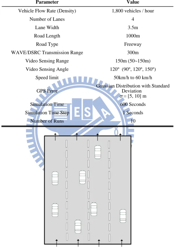
In this chapter, we conduct simulation to evaluate our system using MATLAB [39][40]. The experimental setup was shown in Table 5.1. Our scenario is on the highway model that is 1000 meters straight road contained 4 lanes with 3.5m width, as shown in Figure 5.1. Vehicles are travelling on this road upstream with speed limit from 50km/h to 60km/h and will switch lane randomly. The default vehicle flow rate (density) is medium density with 1800 vehicles/hour, we also simulate the results of 1200, 1800 and 2400 vehicles/hour. The transmission range was set to 300 meters that vehicles have enough ability to communicate with neighbor vehicles. The default sensing range of driving video logger is 150 meters and we will show the different results with several sensing range from 50m to 150m. Also the sensing angle was set to 120 degrees that is common angle used in commercial products. The GPS errors were generated with Gaussian distribution with standard deviation of 5m and 10m. All results are averaged from 10 times of simulations, each run for 600 seconds and vehicles estimate its position per second.
25
Table 5.1 : Simulation parameters
Parameter Value
Vehicle Flow Rate (Density) 1,800 vehicles / hour
Number of Lanes 4
Lane Width 3.5m
Road Length 1000m
Road Type Freeway
WAVE/DSRC Transmission Range 300m
Video Sensing Range 150m (50~150m)
Video Sensing Angle 120° (90°, 120°, 150°)
Speed limit 50km/h to 60 km/h
GPS Error
Gaussian Distribution with Standard Deviation
σ = [5, 10] m
Simulation Time 600 Seconds
Simulation Time Step 1 Seconds
Number of Runs 10
26
5.2. Simulation Results
In our experiments, we evaluate the error of estimation position by comparing with the true position of vehicles. The performance metric used is root-mean-square error (RMSE) [26] , which is expressed in our experiments as follows:
(4)
RMSE is the common metric used for evaluating the accuracy of positioning. We define the real position of vehicle Vi is Pi* (xi*,yi*) and estimated position of Vi is Pi ( , x yi i) in our
experiments, and the RMSE represents as the average distance between Pi* and Pi with n
samples.
First, we show the lane discrimination between GPS lane and video lane in Figure 5.2. With the GPS error of 5 and 10 meters, this figure has shown the value of |GL – VL| = 0 of vehicles exceeded half of vehicles which are less position error than others, the result represent that half of vehicle with low error can help other vehicles to correct their position.
27
Figure 5.3(a) shows the RMSE of the estimated positions with all vehicles are fully equipped and the sensing range is set to 50m and 150m respectively. When sensing range is 50m, the results show the position error can be reduced 25 to 30 percent (around 3.6m). When sensing range is set to 150m and scaling factor α = 1, GPS error of 5m, the position error is under 3.3m. When α larger than 4, the error can less than 3m. But we found that when α > 6 the error could get larger in some cases. So, we set α = 5 as the default value of our system. The Figure 5.4 has shown the value of α is 4~6 and the weight is less than 1/5 with |GL – VL| = 1, that shows |GL – VL| = 1 can improve some accuracy. This figure also shows the helpless when |GL – VL| > 2. In the Figure 5.3(b) shows the RMSE when GPS error is 10m and sensing range is 150m, which can reduce the position error to 5.8m with the value of σ was 4~6. The improvement rate of VIP with different value of α and GPS error σ is shown in Figure 5.5. It shows the equal improving ability of VIP in different GPS errors and sensing ranges, and the accuracy by factor of 30 and 40 percent improvement respectively when α > 4.
(a) With GPS error of 5m (b) With GPS error of 10m Figure 5-3 : RMSE with different values of the scaling factor and GPS error
1 2 3 4 5 6 7 8 9 10 0 0.5 1 1.5 2 2.5 3 3.5 4 4.5 5 α R M S E ( m et er ) GPS Error (σ = 5)
VIP Error (σ = 5, sensing range = 150m) VIP Error (σ = 5, sensing range = 50m)
1 2 3 4 5 6 7 8 9 10 5 5.5 6 6.5 7 7.5 8 8.5 9 9.5 10 α R M S E ( m et er ) GPS Error (σ = 10)
VIP Error (σ = 10, sensing range = 150m) VIP Error (σ = 10, sensing range = 50m)
28
Figure 5-4 : Distribution of position validation under different scaling factor
Figure 5-5 : Improvement rate with scaling factor and GPS error
1 2 3 4 5 6 7 8 9 10 0 0.1 0.2 0.3 0.4 0.5 0.6 0.7 0.8 0.9 1 α P os it ion V al idat ion ( ρ α ) ± 0 ± 1 ± 2 ± 3 1 2 3 4 5 6 7 8 9 10 0 0.1 0.2 0.3 0.4 0.5 0.6 0.7 0.8 0.9 1 α Im pr ov em ent r at e
VIP Error (σ = 10, sensing range = 150m) VIP Error (σ = 5, sensing range = 150m) VIP Error (σ = 10, sensing range = 50m) VIP Error (σ = 5, sensing range = 50m)
29
We also evaluate the accuracy with different ratio of fully equipped vehicles in Figure 5.6. With increasing the ratio of fully equipped vehicles the improvement of positioning accuracy also arises. When the ratio of fully equipped vehicles is less than 30 percent, the average number of neighbor vehicles is not enough, it makes the improvement of estimations results not obviously. The number of neighbor vehicles is around 7 vehicles with the all vehicles are fully equipped and sensing range is 150m, it can provide the best correction result in VIP system. In the Figure 5.7 we can see when the ratio of fully equipped vehicles more than 50 percent, the ratio of estimated vehicle is over 70 and 90 percent in different sensing ranges. It shows VIP system can improve the accuracy of positioning did not require that all vehicles need to equipped with a driving video logger.
(a) With GPS error of 5m (b) With GPS error of 10m
Figure 5-6 : RMSE with different ratio of fully equipped vehicles
0% 10% 20% 30% 40% 50% 60% 70% 80% 90% 100% 0 0.5 1 1.5 2 2.5 3 3.5 4 4.5 5
Ratio of fully equipped vehicles
R M S E ( m et er ) GPS Error
VIP Error (sensing range = 150m, total vehicles) VIP Error (sensing range = 50m, total vehicles) VIP Error (sensing range = 150m, correction vehicles) VIP Error (sensing range = 50m, correction vehicles)
0% 10% 20% 30% 40% 50% 60% 70% 80% 90% 100% 5 5.5 6 6.5 7 7.5 8 8.5 9 9.5 10
Ratio of fully equipped vehicles
R M S E ( m et er ) GPS Error
VIP Error (sensing range = 150m, total vehicles) VIP Error (sensing range = 50m, total vehicles) VIP Error (sensing range = 150m, correction vehicles) VIP Error (sensing range = 50m, correction vehicles)
30
(a) With sensing range of 50m (b) With sensing range of 150m Figure 5-7 : Measure the ratio of correction vehicle with different ratio of fully equipped
vehicles
Figure 5.8 measure the accuracy with different vehicle flow rates. With the rate of 1,200 vehicles/hour, it shows the improvement of positioning lower than 1,800 vehicles/hour, because the former’s number of neighbor vehicles is less than the later that the reference vehicles is not enough for providing good correction. The vehicle flow rate of 2,400 vehicles/hour is better than 1,800 vehicles/hour, and when ratio of fully equipped vehicles less than 90 percent and sensing range is 150m that the RMSE of estimation position is less than 3m. 10% 20% 30% 40% 50% 60% 70% 80% 90% 100% 0 0.1 0.2 0.3 0.4 0.5 0.6 0.7 0.8 0.9 1
Ratio of fully equipped vehicles
R at io of c or rec ti on v ehi c les 10% 20% 30% 40% 50% 60% 70% 80% 90% 100% 0 0.1 0.2 0.3 0.4 0.5 0.6 0.7 0.8 0.9 1
Ratio of fully equipped vehicles
R at io of c or rec ti on v ehi c les
31
Figure 5-8 : RMSE with vehicle flow rates
The comparisons of the accuracy with different video sensing range and angle have shown in Figure 5.9 and Figure 5.10. In these results, we change the video sensing range from 50m to 150m. The result shows the larger sensing range may provide more number of neighbor vehicles, and then get better positioning. The sensing angle may have not any effect of positioning accuracy. Because these angles can coverage most of vehicles, the effect of number of neighbor vehicle is very low.
0% 10% 20% 30% 40% 50% 60% 70% 80% 90% 100% 0 0.5 1 1.5 2 2.5 3 3.5 4 4.5 5
Ratio of fully equipped vehicles
R M S E ( m et er )
1200 Vehicles / Hour, Sensing range = 150m 1800 Vehicles / Hour, Sensing range = 150m 2400 Vehicles / Hour, Sensing range = 150m 1200 Vehicles / Hour, Sensing range = 50m 1800 Vehicles / Hour, Sensing range = 50m 2400 Vehicles / Hour, Sensing range = 50m
32
Figure 5-9 : RMSE with sensing ranges
Figure 5-10 : RMSE with sensing angles
0% 10% 20% 30% 40% 50% 60% 70% 80% 90% 100% 0 0.5 1 1.5 2 2.5 3 3.5 4 4.5 5
Ratio of fully equipped vehicles
R M S E ( m et er ) Sensing range = 50m Sensing range = 75m Sensing range = 100m Sensing range = 125m Sensing range = 150m 0% 10% 20% 30% 40% 50% 60% 70% 80% 90% 100% 0 0.5 1 1.5 2 2.5 3 3.5 4 4.5 5
Ratio of fully equipped vehicles
R M S E ( m et er )
Sensing angle = 150°, Sensing range = 150m Sensing angle = 120°, Sensing range = 150m Sensing angle = 90°, Sensing range = 150m Sensing angle = 150°, Sensing range = 50m Sensing angle = 120°, Sensing range = 50m Sensing angle = 90°, Sensing range = 50m
33
We also evaluate the VIP system with 2, 3 and 4 lanes. The result has shown in Figure 5-11, the improvement rate of 2 and 3 lanes are similar, and the best result is 21 percent. When all of vehicles are fully equipped vehicles and sensing range is 50m, the improvement rate is around 13 percent (4.3m), and the rate of 4 lanes is 2 times greater than 2 and 3 lanes. It means our system is working better on 4 lanes.
Figure 5-11 : RMSE with different number of lanes
Finally, we assume the relative positions obtained by video sensing have error. We add 1~5% distance error in the relative positions. As shown in Figure 5-12, when the sensing range is 50m, the distance error is from 0.5m to 2.5m, the result has shown the error will reduce the accuracy of positioning. When the ratio of fully equipped vehicles is less than 30 percent, the RMSE of VIP is higher than GPS error. If all vehicles are fully equipped, the improvement rate is 12 percent (4.35m).
0% 10% 20% 30% 40% 50% 60% 70% 80% 90% 100% 0 0.5 1 1.5 2 2.5 3 3.5 4 4.5 5
Ratio of fully equipped vehicles
R M S E ( m et er )
2 Lanes, Sensing range = 50m 2 Lanes, Sensing range = 150m 3 Lanes, Sensing range = 50m 3 Lanes, Sensing range = 150m 4 Lanes, Sensing range = 50m 4 Lanes, Sensing range = 150m
34
Figure 5-12 : RMSE with video sensing error
0% 10% 20% 30% 40% 50% 60% 70% 80% 90% 100% 0 0.5 1 1.5 2 2.5 3 3.5 4 4.5 5
Ratio of fully equipped vehicles
R M S E ( m et er ) VIP Error (σ = 5)
35
Chapter 6 Conclusion
In this thesis, we have proposed a Video-Assisted Inter-Vehicle Positioning (VIP) system. The system has been designed to integrate sensed data extracted from driving video logger with image processing and share to information among vehicles to improve the accuracy of cooperative positioning. Simulation results have shown that our approach can achieve 10 and 30 percent of improvement in the position accuracy when only half of vehicles were fully equipped with different sensing ranges, and improve the accuracy by factor of 40 percent (within 3m) if all vehicles were fully equipped in the best condition. In the future works, it is essential to evaluate the performance under different types of driving video logger and image professor (or software), and to consider how to achieve cooperative positioning in the city environments, which could be much more complex compared with highway scenarios. Besides, it is interested to evaluate the performance if the information obtained by a driving video logger, e.g. lane index, distance, license plate number, are not always accuracy.
36
Reference
[1] M. L. Sichitiu and M. Kihl, “Inter-vehicle communication systems: a survey”, IEEE
Communications Surveys & Tutorials, Vol.10, No.2, pp.88-105, 2008.
[2] IEEE Standard for Information Technology - Telecommunications and Information Exchange
Between Systems - Local and Metropolitan Area Networks - Specific Requirements; Part 11: Wireless LAN Medium Access Control (MAC) and Physical Layer (PHY) Specifications; Amendment 6: Wireless Access in Vehicular Environments, IEEE Std. 802.11p, July 2010.
[3] C. Campolo , A. Cortese and A. Molinaro, “CRaSCH: A cooperative scheme for service channel reservation in 802.11p/WAVE vehicular ad hoc networks”, International Conference
on Ultra Modern Telecommunications & Workshops, pp.1-8, Oct. 2009.
[4] D. Jiang , V. Taliwal, A. Meier, W. Holfelder and R. Herrtwich, “Design of 5.9 ghz dsrc-based vehicular safety communication”, IEEE Wireless Communications, Vol. 13, No.5, pp.36-43, Oct. 2006.
[5] Draft Guide for Wireless Access in Vehicular Environments - Architecture, IEEE P1609.0/D3.2, Apr. 2012.
[6] Draft Standard for Wireless Access in Vehicular Environments - Security Services for
Applications and Management Messages, IEEE P1609.2/D15, Apr. 2012.
[7] IEEE Standard for Wireless Access in Vehicular Environments - Networking Services, IEEE Std. 1609.3-2010, Dec. 2010.
[8] IEEE Standard for Wireless Access in Vehicular Environments - Multi-Channel Operation, IEEE Std. 1609.4-2010, Feb. 2011.
[9] Draft Standard for Wireless Access in Vehicular Environments - Remote Management Services, IEEE P1609.6/D0, Apr. 2012.
[10] IEEE Standard for Wireless Access in Vehicular Environments - Over the Air Electronic
Payment Data Exchange Protocol for Intelligent Transportation Systems (ITS), IEEE Std.
37
[11] Draft Standard for Wireless Access in Vehicular Environments - Identifier Allocations, IEEE P1609.12/D7, Jun. 2012.
[12] H. Moustafa and Y. Zhang, “Vehicular Networks-Techniques, Standards, and Applications,”
Auerbach publishers, 2009.
[13] A. Benslimane, “Optimized Dissemination of Alarm Messages in Vehicular Ad-Hoc Networks (VANET)”, In Proc. of International Conference on High Speed Networks and Multimedia
Communications, Vol. 3079/2004, pp.655-666, 2004.
[14] C. Maihöfer and R. Eberhardt, “Time-stable geocast for ad hoc networks and its application with virtual warning signs”, Computer Communications, Vol. 27, No.11, pp.1065-1075, July 2004.
[15] S. Biswas, R. Tatchikou and F. Dion, “Vehicle-to-Vehicle Wireless Communication Protocols for Enhancing Highway Traffic Safety”, IEEE Communications Magazine, Vol. 44, No.1, pp.74-82, Jan. 2006.
[16] F. Ye, M. Adams and S. Roy, “V2V Wireless Communication Protocol for Rear-End Collision Avoidance on Highways”, In Proc. of IEEE International Conference on Communications
Workshops, pp.375-379, May 2008.
[17] B. Hoh, M. Gruteser, R. Herring, J. Ban, D. Work, J. Herrera, A. M. Bayen, M. Annavaram and Q. Jacobson, “Virtual trip lines for distributed privacy-preserving traffic monitoring” In Proc. of
the international conference on Mobile systems, applications, and services, pp.15-28, 2008.
[18] A. Benmimoun, J.Chen and T. Suzuki, “Design and practical evaluation of an intersection assistant in real-world tests”, In Proc. of the IEEE Intelligent Vehicles Symposium, pp.606-611, June 2007.
[19] Z. H. Xiao, Z. Q. Guan and Z. H. Zheng, “The Research and Development of the Highway's Electronic Toll Collection System”, International Workshop on Knowledge Discovery and Data
Mining, pp.359-362, 2008.
[20] A. Boukerche, H. Oliveira, E. Nakamura and A. Loureiro, “Vehicular Ad Hoc Networks: A New Challenge for Localization-Based Systems”, Computer Communications, Vol. 31, No.12, pp.2838-2849, July 2008.
[21] M. Grewal, L.Weill and A. Andrews, “Global Positioning Systems, Inertial Navigation and Integration”, New York: Wiley, 2001.
[22] J. A. Farrell, T. D. Givargis and M. J. Barth, “Real-Time Differential Carrier Phase GPS-Aided INS”, IEEE Transactions on Control Systems Technology, Vol. 8, No.4, pp. 709-721, July 2000. [23] S. Rezaei and R. Sengupta, “Kalman filter based integration of DGPS and vehicle sensors for
38
localization”, IEEE International Conference on Mechatronics and Automation, Vol. 1, pp.455-460, Aug. 2005.
[24] W. Ochieng, J. Polak, R. Noland, J. Y. Park, L. Zhao, D. Briggs, J. Gulliver, A. Crookell, R. Evans, M. Walker and W. Randolph, “Integration of GPS and dead reckoning for real-time vehicle performance and emissions monitoring”, GPS Solutions, Vol. 6, No.4. , pp.229-241, Mar. 2003.
[25] M. Davy, E. Duflos and P. Vanheeghe, “Particle Filtering for Multisensor Data Fusion With Switching Observation Models: Application to Land Vehicle Positioning”, IEEE Transactions
on Signal Processing, Vol. 55, No.6, pp.2703-2719, June 2007.
[26] R. Parker and S. Valaee, “Vehicle Localization in Vehicular Networks”, In Proc. of IEEE
Vehicular Technology Conference, pp.1-5, Sep. 2006.
[27] N. Alam, A. Tabatabaei Balaei and A. G. Dempster, “A DSRC Doppler-Based Cooperative Positioning Enhancement for Vehicular Networks With GPS Availability”, IEEE Transactions
on Vehicular Technology, Vol. 60, No.9, Nov 2011.
[28] S. Fujii, A. Fujita, T. Umedu, S. Kaneda, H. Yamaguchi, T. Higashino and M. Takai, “Cooperative Vehicle Positioning via V2V Communications and Onboard Sensors”, IEEE
Vehicular Technology Conference, pp.1-5 , Sep. 2011.
[29] J. Huang and H.-S. Tan, “A Low-Order DGPS-Based Vehicle Positioning System Under Urban Environment”, IEEE/ASME Transactions on Mechatronics, Vol. 11, No.5, pp.567-575, Oct. 2006.
[30] M. Matosevic, Z. Salcic and S. Berber, “A Comparison of Accuracy Using a GPS and a Low-Cost DGPS”, IEEE Transactions on Instrumentation and Measurement, Vol. 55 , No.5, pp.1677-1683, Oct. 2006.
[31] M. Aly, “Real time detection of lane markers in urban streets”, IEEE Intelligent Vehicles
Symposium, pp.7-12, June 2008.
[32] J.C. McCall and M.M. Trivedi, “Video-Based Lane Estimation and Tracking for Driver Assistance Survey System and Evaluation”, IEEE Transactions on Intelligent Transportation
Systems, Vol. 7, No.1, pp.20-37, Mar. 2006.
[33] M. A. Quddus and W. Y. Ochieng, Z. Lin Zhao, R. B. Noland, “A general map matching algorithm for transport telematics applications”, GPS Solutions, Vol. 7, No.3, pp.157-167, 2003. [34] J. Du and M. J. Barth, “Next-Generation Automated Vehicle Location Systems: Positioning at
the Lane Level” IEEE Transactions on Intelligent Transportation Systems, Vol. 9, No.1, pp.48-57, Mar. 2008.
39
[35] K. Muthukrishnan, M. Lijding and P. Havinga, “Towards Smart Surroundings: Enabling Techniques and Technologies for Localization”, In Proc. of International Workshop on Locati
on-and Context-Awareness, Vol. 3479, pp.209-227, 2005.
[36] G. Sun, J. Chen, W. Guo and K.J.R. Liu, “Signal processing techniques in network-aided positioning: a survey of state-of-the-art positioning designs”, IEEE Signal Processing Magazine, Vo. 22, No.4, pp.12-23, July 2005.
[37] R. Parker and S. Valaee, “Vehicular Node Localization Using Received-Signal-Strength Indicator”, IEEE Transactions on Vehicular Technology, Vol. 56, No.6, pp.3371-3380, Nov. 2007.
[38] J. Xu, W. Liu, F. Lang, Y. Zhang and C. Wang, “Distance Measurement Model Based on RSSI in WSN”, Wireless Sensor Network, Vol. 2, No.8, pp.606-611, Aug. 2010.
[39] D.M. Etter, D. Kuncicky and D. Hull, “Introduction to MATLAB 7”, Prentice Hall, 2005. [40] W.J. Palm, “Introduction to MATLAB 7 for Engineers”, McGraw Hill, 2003.
[41] C.A. Rahman, W. Badawy and A. Radmanesh, “A real time vehicle's license plate recognition system”, In Proc. of IEEE Conference on Advanced Video and Signal Based Surveillance, pp.163-166, July 2003.
[42] S.-L. Chang, L.-S. Chen, Y.-C. Chung and S.-W. Chen, “Automatic license plate recognition”
IEEE Transactions on Intelligent Transportation Systems, Vol. 5, No.1, pp.42-53, Mar. 2004.
[43] D. R. Magee, “Tracking multiple vehicles using foreground, background and motion models”,
Image and Vision Computing, Vol. 22, No.2, pp.143-155, Feb. 2004.
[44] B.-F. Wu, W.-H. Chen, C.-W. Chang, C.-J. Chen and M.-W. Chung, “A New Vehicle Detection with Distance Estimation for Lane Change Warning Systems”, IEEE Intelligent Vehicles
Symposium, pp.698-703, June. 2007.
[45] S. Zhu, H. Zhu and M. Zhou, “A design of vehicle collision avoidance system based on DSP”,