國
立
交
通
大
學
資訊學院 資訊學程
碩
士
論
文
快速 OFDM 訊框時間差估計方法之設計與其在
無線中繼網路降低換手頻率之研究
Fast OFDM Frame Inter-Arrival Time Differences Estimation
and Its Application to Handoff Reduction in Wireless Relay Networks
研 究 生:陳政敏
指導教授:王蒞君 教授
曾煜棋 教授
快速 OFDM 訊框時間差估計方法之設計與其在
無線中繼網路降低換手頻率之研究
Fast OFDM Frame Inter-Arrival Time Differences Estimation
and Its Application to Handoff Reduction in Wireless Relay Networks
研 究 生:陳政敏 Student:Cheng-Min Chen
指導教授:王蒞君 Advisor:Dr. Li-Chun Wang
曾煜棋
Dr. Yu-Chee Tseng
國 立 交 通 大 學
資訊學院 資訊學程
碩 士 論 文
A Thesis
Submitted to College of Computer Science National Chiao Tung University in partial Fulfillment of the Requirements
for the Degree of Master of Science
in
Computer Science July 2008
Hsinchu, Taiwan, Republic of China
快速 OFDM 訊框時間差估計方法之設計與其在
無線中繼網路降低換手頻率之研究
學生:陳政敏
指導教授
:王蒞君 教授
曾煜棋 教授
國 立 交 通 大 學
資 訊 學 院 資 訊 學 程 碩 士 班
摘
要
本論文係研究在一個廣泛佈建
OFDM 無線中繼網路的都會區域中,快速移
動的用戶端設備遭遇換手次數頻繁之問題,並提出相關的解決方案。在
OFDM
無線中繼網路中,引入一個新的網路元件-中繼站(Relay Station),用以改善因建
築物遮蔽所產生的訊號品質衰落問題,並藉以提高訊號涵蓋範圍。中繼站具備完
整 訊 框 結 構 , 對 基 站
(Base Station)而言,中繼站被視為一個用戶端(Mobile
Station);對用戶端而言,中繼站扮演基站的角色。隨著中繼站佈建數量的增加,
快速移動的用戶端將面臨換手次數提高的問題。
在一個以
OFDM 為基礎的通信系統中,訊框同步是個重要的議題。對於一
個快速移動的用戶端而言,此問題尤其嚴重。但接收機在處理訊框同步過程中所
估算到的訊框長度差,卻恰好可作為反應基站(含中繼站)與用戶端之間相對運動
的參數。基於此參數,我們設計一個新的換手目標選擇指標,以有效的抑制換手
次數的提升。
本論文的第一部分提出一個基於實體層的快速訊框到達時間估算方法。
OFDM 無線中繼網路的訊框結構中,不論是基站或中繼站,均擁有獨立的廣播標
頭(Preamble)。此標頭以 BPSK 調變,在通過 IFFT 區塊之後,會呈現獨特的對稱
特性。藉此特性,我們可以完成訊框到達事件偵測,並得到
FFT 長度與循環字
首(Cyclic Prefix)的長度,而不須預先經過 MAC 層控制信令傳送給接收機端。藉
由上述實體層資訊,我們可以估測訊框到達時間以及訊框長度,並與系統預設之
訊框長度作比較後可以得到訊框時間差。
本論文第二部份設計一個新的換手目標選擇指標,並實作一個模擬都會區域
廣泛佈建中繼站的類曼哈頓(Manhattan-like)模擬器。此模擬器實做 IEEE 802.16j
相關實體層參數、信號衰落模型,以驗證新指標的性能。模擬結果顯示此新指標
能有效抑制換手頻率,對於降低換手次數有顯著的效果。
Fast OFDM Frame Inter-Arrival Time Differences Estimation
and Its Application to Handoff Reduction in Wireless Relay Networks
Student:Cheng-Min Chen
Advisors:Dr. Li-Chun Wang
Dr. Yu-Chee Tseng
Degree Program of Computer Science
National Chiao Tung University
ABSTRACT
In this thesis, we investigate how to efficiently using the relative movement
information of MS to reduce handoff event and control signaling overhead for
OFDM-Based wireless relay networks. In wireless relay networks, the relay station
(RS) is introduced to improve the link quality and coverage. However, RS may
cause the increase handoffs when an MS moves across the boundary betweens RS
and BS, thereby result in signaling overhead for handoff. A handoff algorithm in
wireless relay networks should intelligently reduce unnecessary handoffs.
Firstly, we develop a frame arrival event detection and frame arrival time
estimation algorithm based on fast PHY-layer Schemes for obtaining cyclic prefix (CP)
Lengths and fast Fourier transform (FFT) Sizes. Traditionally, CP length and FFT size
are broadcasted via media access control (MAC) layer to pre-handoff MS. The
algorithm we proposed is based on the conjugated symmetry characteristics of binary
phase shift keying (BPSK) modulated preamble.
Secondly, the difference of the estimated consequent frame inter-arrival time
could be used to judge that MS moves toward a RS or leaving away a RS. This is
called the relative movement information, which is considered to develop a
time-of-arrival based target selection algorithm for handoff procedure.
In simulated Manhattan-like urban model, physical layer parameters, path-loss
model and handoff procedure of IEEE 802.16j are implemented. We evaluate the
performance of the proposed algorithm. Our result shows that proposed algorithm can
reduce the handoff frequency significantly compared to traditional signal-based target
selection.
我的論文,終於告個段落。要不是上帝的眷顧,我無法度過無數個台北新竹
來回奔波的夜晚。從小就覺淂讀書不是件容易的事,為了很多原因,我堅持了下
來。但其中最重要的,是家人(父、母、兄、妹)的支持與鼓勵,沒有他們作為心
靈上的後盾,我沒有辦法撐過來。
我要感謝我的指導教授-王蒞君教授。我與老師研討論文的過程,堪稱夙夜
匪懈。老師精確的檢視論文的內容,並指出裡頭的邏輯錯誤。沒有老師的指導,
我無法完成這些。我也要感謝我的共同指導教授-曾煜棋教授。因為曾教授願意
擔任共同指導,我才有機會從資工領域跨入通信領域。
此外,實驗室裡的建華學長、維正學長、中瑋學長、偉賢,給了許多研究上
的協助及建議,感謝上帝讓我遇見這麼多好人與這麼多金頭腦。
身為一個來自花蓮的阿美族人,我也要將此份論文獻給吉安鄉娜荳蘭部落的
族人親友與祖靈。但願這份論文,也帶著一些山與海的味道。
-Adop
Contents
Summary . . . v
List of Tables . . . ix
List of Figures . . . x
1. Introduction . . . 1
1.1 Problems and Solutions . . . 2
1.1.1 OFDM Frame Arrival Time Estimation based on Fast PHY-layer Schemes for Obtaining CP Lengths and FFT Sizes . . . 4
1.1.2 Difference of Frame Inter-arrival Time Based Target Selection Scheme for Reducing Handoffs in Wireless Multi-hop Relay Net-works . . . 5
1.2 Thesis Outline . . . 5
2. Background . . . 7
2.1 OFDMA Physical Layer in IEEE 802.16 Standard . . . 7
2.2 Introduction to IEEE 802.16j Multi-hop Relay Networks . . . 9
2.3 Handoff Procedure in IEEE 802.16j Multi-Hop Relay Network . . . . 13
2.4 Frame Structure of IEEE 802.16j OFDMA Air Interface . . . 17
2.5 OFDMA Subcarrier Allocations in Downlink Subframe . . . 19
3. Frame Arrival Detection and Estimation of FFT Size and CP Length . . . 23
3.1 Introduction . . . 23
3.2 System Model . . . 25
3.3 Conjugated Symmetric Characteristics of BPSK Modulated Preamble 27 3.4 Proposed Frame Arrival Detection and FFT Sizes Estimation Algorithms 31 3.5 Proposed CP Length Estimation Algorithm . . . 35
3.6 Simulation Results . . . 36
3.7 Conclusion . . . 38
4. Frame Arrival Time Estimation . . . 39
4.1 Introduction . . . 39
4.2 System Model . . . 40
4.3 Proposed CP-based Frame Arrival Time Estimation Algorithm . . . . 41
4.4 Simulation Result . . . 42
4.5 Conclusion . . . 43
5. Difference of Frame Inter-arrival Time Based Target Selection Scheme for Re-ducing Handoffs in Wireless Multi-hop Relay Networks . . . 45
5.1 Introduction . . . 45
5.2 System model . . . 46
5.2.1 Manhattan-like Urban Model . . . 46
5.2.2 Path Loss Model . . . 47
5.3 Relative Movement Indicator of Mobile Station . . . 49
5.4 Proposed Difference of Frame Inter-arrival Time Based Target Selec-tion Algorithm . . . 53
5.5 Simulation Result . . . 54
5.6 Conclusion . . . 55
Contents viii
6.1 OFDM Frame Arrival Time Estimation based on Fast PHY-layer Schemes
for Obtaining CP Lengths and FFT Sizes . . . 59
6.2 Difference of Frame Inter-arrival Time Based Target Selection Scheme for Reducing Handoffs in Wireless Multi-hop Relay Networks . . . 60
6.3 Suggestion for Future Work . . . 60
Bibliography . . . 62
5.1 Manhattan-like urban model . . . 47 5.2 Additional path loss model in IEEE 802.16j networks . . . 48 5.3 System parameters . . . 56
List of Figures
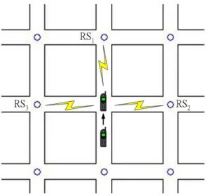
1.1 A example of handoff scenario. . . 3
1.2 Time difference of frame arrival caused by relative mobility. . . 4
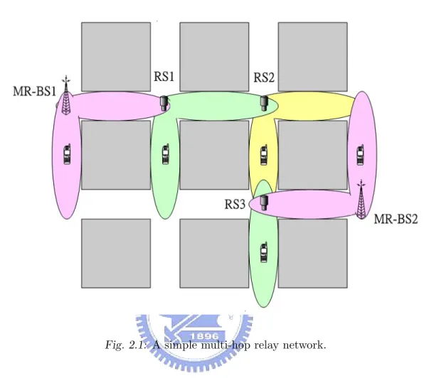
2.1 A simple multi-hop relay network. . . 9
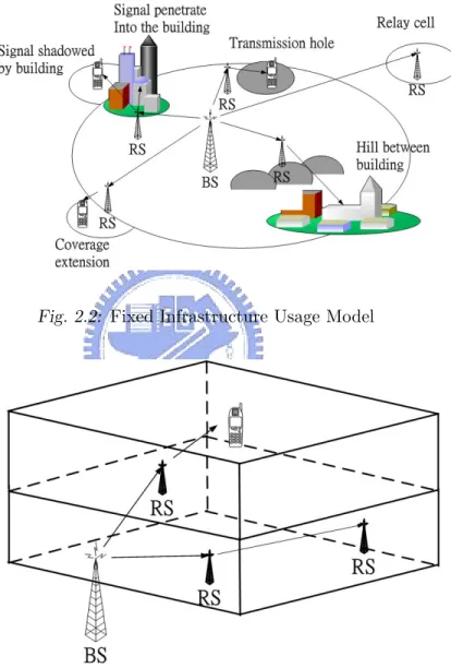
2.2 Fixed Infrastructure Usage Model . . . 11
2.3 In-Building Coverage Usage Model . . . 11
2.4 Temporary Coverage Usage Model . . . 12
2.5 Coverage on Mobile Vehicle Usage Model . . . 12
2.6 Seven handoff cases in an relay network. . . 14
2.7 Network topology advertisement in IEEE 802.16j . . . 15
2.8 Message flow of MOB NBR-ADV transmission . . . 15
2.9 Handoff Initiation in IEEE 802.16j. . . 16
2.10 The Suggested Frame Structure for IEEE 802.16j. . . 17
2.11 Frame structure for non-transparent mode. . . 18
2.12 The preamble structure of IEEE 802.16j OFDMA 1024 FFT points air interface. . . 20
2.13 The channel structure of SUI channel model. . . 22
3.1 The system model of N -subcarrier OFDM transmission system. . . . 26
3.2 Symmetric characteristics of BPSK modulated preamble after discrete-time fourier transform. . . 30
3.3 Correlation value of symmetric characteristics of BPSK modulated
preamble. . . 30
3.4 The auto-correlation value and threshold to detect frame arrival event. 32 3.5 Proposed algorithm of frame arrival detection, FFT size estimation and CP length estimation. . . 33
3.6 The average difference of auto-correlation value for frame arrival de-tection and CP length estimation. . . 34
3.7 The comparison of successful probability of frame arrival detection under AWGN channel. . . 36
3.8 The comparison of successful probability of frame arrival detection under SUI-3 channel. . . 37
3.9 The comparison of successful probability of cyclic prefix (CP) ratio under AWGN and SUI-3. . . 38
4.1 Concept of pre-FFT equalizer. . . 41
4.2 The comparison of successful probability frame arrival time estimation under AWGN and SUI-3 channel. . . 43
5.1 Two deployment model of RS . . . 48
5.2 Example of path-loss Type-F. . . 50
5.3 The complete process to estimate the RMI. . . 51
5.4 Simulation result under uniform distribution of RS . . . 57
CHAPTER 1
Introduction
The orthogonal frequency division multiplexing (OFDM) based systems have become a main stream in the next generation communication system, such as 3rd generation partnership project long term evolution (3GPP LTE), 3rd generation partnership project 2 air interface evolution (3GPP2 AIE) and worldwide interoperability for mi-crowave access (WiMAX). For above systems, there are two identical features in them: higher transmission rate and more intelligent functions. Their common characteristic is that OFDM-based technique is adopted in the physical layer.
OFDM possess many advantages. It converts a frequency selective fading channel into parallel collection of frequency flat fading sub-channels, thereby over-comes the inter-symbol interference (ISI). It also allows overlapped sub-carriers and maintains their orthogonality to achieve higher spectrum efficiency.
The OFDM-based IEEE 802.16 standard is designed for local and metropolitan area networks. The IEEE 802.16-2004 standard defines the air interface and medium control message for the fixed broadband wireless access systems. The IEEE 802.16e standard extends the application from the fixed system to the mobile system. The IEEE 802.16j standard is based on the IEEE 802.16e standard which introduced relay
station (RS) to improve link quality and system coverage. The RS forwards the signal from one station to another one or to the managed mobile station (MS). A new frame structure is designed to contain the subframe of RS in the downlink subframe of a base station (BS). In each subframe the preamble is used for synchronization between RS and MS. From the viewpoint of the MS, an RS looks like a BS. However, for the BS, an RS also looks like an MS. Thus the RS plays two roles in the IEEE 802.16j networks.
1.1
Problems and Solutions
In the metropolitan environment, the signals are reflected and shadowed by the build-ing. Thus the link quality and coverage degrade rapidly. Deploying RSs widely can solve this problem. Since the RS acts as a BS, handoffs will be triggered when the signal strength is lower than the specific threshold. The more relay stations deployed, the higher handoff frequency we may have. Thus, signaling overheads increase and may interrupt upper layer application service [1]. The objective of this thesis is to design an efficient target selection algorithm to reduce handoff frequency and control signaling overhead.
The Fig. 1.1 shows an example while an MS needs to handoff. The conven-tional handoff algorithm depends on the received signal strength indicator (RSSI) to decide whether the handoff is necessary and determine the selected target station. The MS in the figure may handoff to RS2 first and then handoff to RS1. In fact,
if the received signal strength from RS1 is good enough, MS shall handoff to RS1
directly. Thus it is unnecessary to trigger the handoff process to RS2.
To solve this problem, we suggest to include the mobility pattern of MS in the target selection algorithm. The mobility pattern can be represented by the relative movement Indicator (RMI) according to the difference between observed frame
inter-CHAPTER 1. Introduction 3
Fig. 1.1: A example of handoff scenario.
arrival time and the predefined frame inter-arrival time, which is called the difference of frame inter-arrival time. Since each sub-frame has the preamble for synchronization between RS and MS, RS looks like a BS for MS. Thus, regardless of a BS or RS the candidate target station is, the RMI can be estimated by the MS. By combining RSSI and RMI, the MS can select the best candidate target station with less unnecessary handoffs.
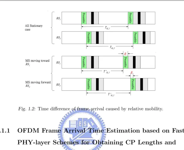
Next, we design a handoff evaluation indicator which integrates RSSI and RMI. When a handoff event is triggered, an MS must select a new target station. The new indicator helps an MS to choose the best target station which hold a longer connection time. With highly deployed RSs, the issue of target selection become very important. In Fig. 1.2, the difference of frame inter-arrival time between MS and RS1 is larger
than that between MS and RS2. In this case, RS1 has higher priority to become the
Fig. 1.2: Time difference of frame arrival caused by relative mobility.
1.1.1
OFDM Frame Arrival Time Estimation based on Fast
PHY-layer Schemes for Obtaining CP Lengths and
FFT Sizes
To estimate the difference of frame inter-arrival time, there are two important things should be discussed: frame arrival detection and frame arrival time estimation. Frame Arrival Detection and Estimation of FFT Sizes and CP Length Frame arrival detection mechanism is to detect frame arrival event. The challenge lies in how to estimate fast Fourier transform (FFT) size and cyclic prefix (CP) length without the help from media access control (MAC) layer because the MS may not received the system control message from BS. We propose a frame arrival detection mechanism based on the fast PHY layer estimation of FFT size and CP length which are usually obtained from the MAC layer and cause long delay and signaling overhead.
CHAPTER 1. Introduction 5
Frame Arrival Time Estimation
The actual frame arrival time should be estimated after a receiver detects the frame arrival event and obtains the information of FFT size and CP length. Though OFDM is designed to overcome ISI, delayed signals from prior symbol still have the chance to interfere with next symbol when CP length is too short. We design a time domain pre-FFT equalizer to deal with this problem.
1.1.2
Difference of Frame Inter-arrival Time Based Target
Selection Scheme for Reducing Handoffs in Wireless
Multi-hop Relay Networks
In the Wireless multi-hop relay systems, the handoff decision and target selection decision are basically based on the RSSI. The handoff frequency will grow propor-tionally to the density of the deployed RS in the metropolitan environment. To solve this problem, we introduce the RMI into the target selection indicator. We integrate RSSI and RMI. For example, when an MS needs to handoff, and there exist two target stations with similar RSSI, an MS can choose the target station with larger RMI value even with smaller RSSI. The connection between MS and selected target station can be hold for a longer time. In our simulations, the proposed idea successfully decreases the handoff frequency.
1.2
Thesis Outline
In this thesis, we investigate how to reduce the handoff frequency, while MS moving in a metropolitan environment. We first design the frame arrival detection based on fast PHY layer scheme for obtaining FFT size and CP length. Next, We discuss how
to estimate the actual frame arrival time. By doing so, we can estimate the mobility pattern (i.e RMI) between the MS and candidate target stations. When considering both RMI and RSSI, we can help an MS to select a more suitable target station during handoff.
The remaining chapters of this thesis are organized as follows. In Chapter 2 we introduce the background of the physical layer in the IEEE 802.16 wireless metropolitan area network (WMAN). We introduce the frame structure and synchro-nization process for the handoff procedure. In Chapter 3, we provides a frame arrival detection algorithm for obtaining FFT size and CP length which based on the conju-gated symmetric characteristics of The binary phase shift keying (BPSK) modulated preamble. Latter, we discusses the frame arrival time estimation algorithm in Chap-ter 4, and compare the performance of traditional algorithm and proposed algorithms under the AWGN channel and the SUI-3 channel. In Chapter 5, a novel RMI esti-mation algorithm is proposed. We simulate the proposed target selection algorithm for handoff in a Manhattan like urban environment, and give a comparison between traditional indicator and proposed indicator. At last, we give the concluding remarks and suggestions for future work in Chapter 6.
CHAPTER 2
Background
In this chapter, we introduce the background of the orthogonal frequency-division multiple access (OFDMA) physical layer in the IEEE 802.16 wireless metropolitan area network (WMAN). The concept of synchronization techniques, MAC message flow, and the channel model are also be introduced.
2.1
OFDMA Physical Layer in IEEE 802.16
Standard
The new radio technology-WiMAX is based on the wireless transmission methods defined by IEEE 802.16 standard. The IEEE 802.16 WirelessMAN [2] [3] specifies the standards for the air interface and MAC protocols for the fixed, portable, and mobile broadband wireless access systems. The typical application of the IEEE 802.16 WiMAX includes mesh networks, backhual, wireless digital subscriber line (DSL) to residential and small-office-and-home-office (SOHO), and broadband mobile networks. The IEEE 802.16-2004 standard specifies OFDM as the transmission method.
The line of sight (LOS) link operates in the 10-66 GHz, and non-line-of-sight (NLOS) link operates in the 11 GHz. The OFDM signal is composed of many orthogonal carriers, and every carrier is modulated with a relatively slow symbol rate. This method has the advantages in a area with multipath channel because more time is needed to transmit a symbol compared to the single carrier method at the same transmission rate.
The guard period is added to the front of every symbol in OFDM-based signal, which is a short copy of the tail of original symbol. It can avoid the multipath effect to radio transmission. These characteristics result in a stable connection because of the very low bit error rate (BER). BPSK, quadrature phase shift keying (QPSK), 16 quadrature amplitude modulation (16QAM), and 64 quadrature amplitude mod-ulation (64QAM) modmod-ulation modes are used, and the modmod-ulation scheme can be adapted to satisfy difference transmission conditions. The IEEE 802.16e standard is an expansion to satisfy the requirement of mobile application and roaming, and it frequency range is up to 6 GHz. The number of carriers can vary over a wide range depending on permutation zones and FFT size (128 to 2048 points).
The IEEE 802.16 standard specifies two flavors of OFDM systems: (1) OFDM and (2)OFDMA. The OFDM method aims at the short distance applications, such as indoors. The FFT size is 256. The downlink (DL) multiplex scheme is time-division multiplexed (TDM), and that in the uplink (UL) is time-division multiple access (TDMA). For OFDMA, the subcarrier in higher FFT size (2048 carriers) are divided into groups, which is called subchannels. It mapping the subcarriers into logical channels in downstream. Those sub-channels using different modulation, coding, and amplitude to fit different channel characteristics.
The IEEE 802.16-2004 and IEEE 802.16e standards have several channel band-widths from 1.5 to 20 MHz. This can be adopted to the configuration of different tranciever platforms. Furthermore, this flexibility is also helpful for cell planning.
CHAPTER 2. Background 9
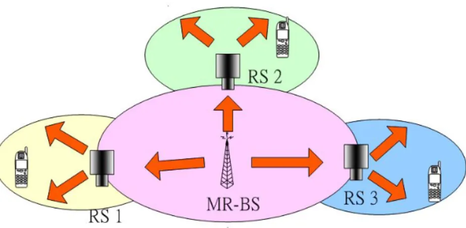
Fig. 2.1: A simple multi-hop relay network.
2.2
Introduction to IEEE 802.16j Multi-hop
Relay Networks
The multi-hop relaying (MR) becomes an important technique for future wireless networks, which can extend the coverage or improve link quality specially in urban environment. A simple MR network is shown in Fig. 2.1.
In the wireless multi-hop relay networks, cell diameter is smaller than that in conventional cellular networks. The coverage of an RS is expected from 200 to 500 meters, thus the transmit power of an RS is smaller than that of multi-hop BS (MR-BS). The small size of coverage makes the deployment easier and more flexible
than that of MR-BS [4].
The IEEE 802.16j is a standard for specifying the wireless multi-hop relay operation used in metropolitan environment [5]. The RS can extend cell coverage, and allows for more efficient frequency reuse. In the reference [6], gives a summary of the usage models for IEEE 802.16j networks. The purpose of usage models is to define different deployment scenarios (such as fixed, nomadic, mobile) to fit the requirements of network elements (such as RS) and functional entities to improve system performance.
The usage models are classified from the perspective of the infrastructure. The usage model maps the different services into different infrastructures. It define four usage models as follow:
1. Fixed Infrastructure Usage Model (I)
In this usage model, the main purpose of deploying RS is coverage expansion. Besides, improving the capacity or per user throughput in areas which are not sufficiently covered by the MR-BS. See the Fig. 2.2.
2. In-Building Coverage Usage Model (II)
In this usage model, an RS provides a better coverage and higher throughput inside the building, tunnel or underground such as on a subway platform. See the Fig. 2.3.
3. Temporary Coverage Usage Model (III)
In this usage model, an RS is deployed temporarily to cover a region which is not included in the original cell planning. See the Fig. 2.4.
4. Coverage on Mobile Vehicle Usage Model (IV)
In this usage model, an RS is deployed in a mobile vehicle which provides MS a stable backhual connection. See the Fig. 2.5.
CHAPTER 2. Background 11
Fig. 2.2: Fixed Infrastructure Usage Model
Fig. 2.4: Temporary Coverage Usage Model
CHAPTER 2. Background 13
2.3
Handoff Procedure in IEEE 802.16j
Multi-Hop Relay Network
The IEEE 802.16j is a extend specification of IEEE 802.16e. The handoff procedure of IEEE 802.16j is based on that of IEEE 802.16e basically, but includes several new scenarios. The common processes of handoff include two stages: network topology acquisition and handoff process execution.
First, in topology acquisition stage, a MR-BS shall broadcast information about the network topology using the MOB NBR-ADV message at a periodic in-terval. The message provides channel information for neighboring BS. A serving BS may obtain that information over the backbone. This information is very important for a MS to synchronize with neighboring BS while MS needs to handoff, it saving the bandwidth and time to monitor transmission of message from the neighboring BS. A BS will allocate time intervals to MS, which used to seeking neighboring BS and making handoff target decision. These time intervals is called the scanning interval.
Second, the handoff process is executed in which an MS decide to change the serving BS. The handoff process consists of the following stages: cell reselection, handoff decision and initiation, synchronization to target BS downlink, Ranging, ter-mination of MS context and handoff cancellation. In the cell reselection stage, an MS scan BSs in order to determine the most suitable target station. The candidate BSs are listed in MOB NBR-ADV message. Then, the serving BS will allocate scanning intervals to MS for cell selection. The more detail processes are described in the reference [3] Section 6.3.22.
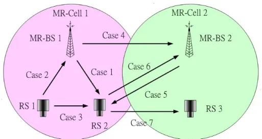
The reference [7] described seven handoff scenarios of IEEE 802.16j network, see Fig. 2.6. An MR-BS owns all the information of associate RSs. These information is encapsulated in MOB NBR-ADV control message, MR-BS broadcast this message
Fig. 2.6: Seven handoff cases in an relay network.
periodically [8]. Each relay link between MR-BS and RS is identified by primary CID, MOB NBR-ADV message will be delivered hop by hop to every associate RSs. Finally, RS broadcast message to its MSs, see the Fig. 2.7 and Fig. 2.8.
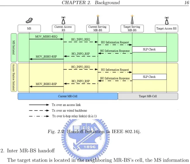
For handoff process execution stage, the selected target station may request the MS information to speed up the process. According to the seven handoff scenarios as mentioned before, MS information may need to delivered over the relay link or wired backbone. Two new MAC management messages MS REQ and MS INFO-RSP were defined in the reference [9] to support the request of target station, see Fig. 2.9.
The handoff process can be categorized into two kinds: intra MR-BS handover and inter MR-BS handover:
1. Intra MR-BS handoff
The target station is in the original MR-BS’s cell. The MS information just needs to delivered over relay link. The signaling overhead is a little bit increased.
CHAPTER 2. Background 15
Fig. 2.7: Network topology advertisement in IEEE 802.16j
Fig. 2.9: Handoff Initiation in IEEE 802.16j.
2. Inter MR-BS handoff
The target station is located in the neighboring MR-BS’s cell, the MS information must delivered over wired backbone. The target station has to issue MS INFO-REQ and MS INFO-RSP over the relay links and/or over the wired backbone to request the MS information. The signaling overhead may be increased rapidly.
The rest stages of handoff are described in the references [7] [10] [11] [9] [12] [13], and the more detail statements are listed in IEEE 802.16’s Relay Task Group.
CHAPTER 2. Background 17
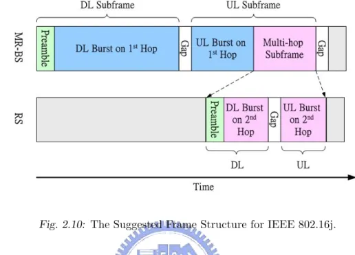
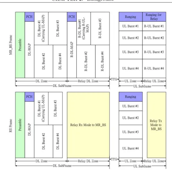
Fig. 2.10: The Suggested Frame Structure for IEEE 802.16j.
2.4
Frame Structure of IEEE 802.16j OFDMA
Air Interface
The IEEE 802.16j standard inherents physical layer specification from IEEE 802.16e air interface. The network topology is mainly a tree-based architecture which con-structed by MR-BS and RSs. An RS recieved signal from one hop (MR-BS or RS), then decode and forward to another hop (MR-BS, RS, or associate MS).
A new frame structure must be provided to support the requirement of signal relaying in the tree-based architecture. Fig. 2.10 shows a suggested frame structure [14]. During the multi-hop subframe interval, the BS does not schedule DL and UL traffic. Instead, RS fully control the assigned frame interval, and encapsulate MAC-layer control message in the frame. This frame is called multi-hop subframe. BS schedule a downlink time zone for RS, then RS can transmit its own frame to the next hop or associated MS.
Fig. 2.11: Frame structure for non-transparent mode.
The multi-hop subframe includes DL subframe and UL subframe. The DL subframe composed of the preamble and DL data burst. The DL data burst contain the MAC-layer control message. The UL subframe starts with a contention interval after DL data burst. MS use this interval for network entry or issues request for bandwidth adaptation.
In the reference [15], it proposes a frame structure with similar concept, see Fig. 2.11. In this design, the RS’s operation is classified into two modes: transparent mode and non-transparent mode. For transparent mode, RS does not transmit its
CHAPTER 2. Background 19
own preamble. Thus, the RS’s operation is fully controlled by the MR-BS, which in-clude control message generation and frame interval scheduling. For non-transparent mode, an RS transmits its own broadcast preamble, FCH, DL-MAP/UL-MAP and DCD/UCD. Each RS is well aware of neighboring station, and it broadcast individ-ual MOB NBR-ADV message for its service area. In this thesis, we focus on the non-transparent mode.
2.5
OFDMA Subcarrier Allocations in Downlink
Subframe
The first symbol of DL subframe is the preamble, and the preamble is modulated using BPSK modulation with well defined pseudo-noise (PN) code [3]. There are three types of preamble carriersets which differ from the allocation of different subcarriers to each other. Assume the FFT size is 1024, the preamble carriersets are defined as (2.1):
P reambleCarrierSetn= n + 3k (2.1)
where:
P reambleCarrierSetn : specif ies all subcarriers allocated to the specif ic
preamble,
n : is the number of the preamble carrier set indexed 0...2,
k : is a running index 0...284.
The PN sequence of IEEE 802.16e OFDMA air interface is defined in the reference [2] [3] Table 309. The value of defined sequence shall be converted (0 mapped to +1 and 1 mapped to -1) from most significant bit (MSB) to least significant bit (LSB), then mapped into the subcarriers. It has to reserve 86 guard band subcarriers
Fig. 2.12: The preamble structure of IEEE 802.16j OFDMA 1024 FFT points air interface.
on the left side and the right side of the spectrum. One example of 1024 FFT points preamble is shown in Fig. 2.12.
2.6
Channel Model
An important technique to evaluate the performance of a wireless system is to trans-mit signals into wireless channel. The wireless channel model should construct the path loss model, multipath delay spread model, fading characteristics, doppler spread, co-channel and adjacent channel interference, etc. Since different architecture of wire-less system has different channel characteristics, thus different channel model should mapping to each usage scenario.
The IEEE 802.16 task group suggested two types of usage scenario: suburban and urban. For suburban, the channel model is based on the Hata-Okumura model and its extension [16] [17] [18] [19]. It is categorized into three types: category A, category B and category C for different path loss categories. The basic path loss formula is:
P L = A + 10γlog(d/d0)
CHAPTER 2. Background 21
where A = 20log(4πd0/λ)
10 (λ being the wavelength in meter), γ is the path-loss exponent
with γ = (a − bhb + c/hb) for hb between 10m and 80m (hb is the height of the base
station in meter), d0 = 100m and a, b, c are constants dependent on the category.
We can adjust the configuration of channel model for other frequencies and for receive antenna heights between 2m and 10m. The modified path loss model would be:
P Lmodif ied = P L + 4P Lf + 4P Lh (2.3)
where P L is the path loss given in equation 2.2, 4P Lf(in dB) is the frequency
correction term, given by
4P Lf = 6log f /2000 10
where f is the frequency in M Hz, and 4P Lh is the receive antenna height correction
term given by:
4P Lh = −10.8 · log (h/2) 10 , Categories A and B 4P Lh = −20 · log (h/2) 10 , Categories C
where h is the receive antenna height between 2m and 10m.
For urban, Cost 231 Walfish-Ikegami (W-I) model is used to describe the chan-nel model with uniform building height. In this model, the path loss effect is influenced by three factors:
Lb = L0+ Lrts+ Lmsd
where L0is free space loss, Lrtsis roof top to street diffraction and Lmsdis multi-screen
loss. The detail can be seen in the reference [20].
In IEEE 802.16j network, the Stanford University Interim (SUI) channel mod-els [21] is adopted to describe the channel characteristics. SUI model gives a general
Fig. 2.13: The channel structure of SUI channel model.
form to include possible combinations of parameters to obtain channel descriptions. SUI model combines all parameters which are mentioned before, and make a mapping to different usage models. The general structure of SUI channel model show in the Figure 2.13 and the detail can be seen in [22].
CHAPTER 3
Frame Arrival Detection and
Estimation of FFT Size and CP
Length
3.1
Introduction
In this chapter, we investigate how to detect the frame arrival event with obtaining FFT size and CP length. The synchronization process usually includes two steps: coarse synchronization and fine synchronization. Frame arrival detection belongs to coarse synchronization which used to detect whether a frame is coming. The fine synchronization mainly estimates the frame starting time. As mentioned before, our goal is to estimate the difference of frame inter-arrival time, which is used for best target selection. To achieve this goal, frame arrival detection must be accomplished first.
of the predefined preamble. A receiver must know the information of FFT size and CP length before it starts to execute synchronization process. If it doesn’t know the FFT size, it will not know when to stop the frame arrival detection process. If it doesn’t know the CP length, it will not know how long a symbol period must be deleted before sending signal into FFT block. Usually, FFT size and CP length are known from the upper layer MAC message.
In our considered case (wireless multi-hop relay networks), an MS needs to compare the difference of frame inter-arrival time from different RSs or BSs to select the most suitable handoff target. Since the target RS or BS has not been decide yet, and system control message may not received from BS, FFT size and CP length of candidate target stations may not be obtained by the MS. Furthermore, the FFT size and CP length are variable in OFDMA-based WiMAX systems. Thus, the frame arrival detection is required to perform without information of FFT size and CP length.
We develop a fast PHY layer solution to estimate FFT size and CP length without depending on any MAC-layer message. This technique help to accomplish the synchronization process more quickly.
The rest of this chapter is organized as follows. In Section II, we describe the system model. In Section III, we discuss the problem of frame arrival detection. In Section IV, we provide frame arrival detection and FFT estimation algorithm which based on the conjugated symmetric characteristic of BPSK modulated preamble. In Section V, we discuss the CP length. In Section VI, we define the performance evalua-tion metrics, and show the simulaevalua-tion results to compare the proposed algorithm with conventional algorithm under different channel model and give concluding remarks in Section VII.
CHAPTER 3. Frame Arrival Detection and Estimation of FFT Size and CP Length 25
3.2
System Model
We consider an N FFT points OFDM system with one transmit antenna and one receive antenna. The total bandwidth of each subchannel is assumed to be smaller than the channel coherent bandwidth.
The FFT-based technique are typically employed in the baseband OFDM mod-ulation/demodulation process as Fig. 3.1. The serial data stream is split to parallel data stream with a data rate of 1/Tsym, which Tsym is symbol duration. The resulting
symbol stream is modulated into a vector of N data symbol X[0] to X[N − 1]. The inverse FFT (IFFT) of the data symbol vector x[0] to x[N − 1] transfer symbol from frequency domain to time domain, this is called the subcarrier. Thus the x[n] are the time domain samples of the OFDM symbol and transmitted sequentially over the channel.
A low complexity technique of preventing the interference of transmitted con-secutive OFDM symbols is to copying a short period of symbol from the symbol tail and adding it to the front of symbol. It is assumed that the CP length is greater than the length of the discrete-time baseband channel impulse response so that the frequency-selective fading channel decouples into a set of parallel frequency-flat fad-ing channels [23]. Denotfad-ing the transmit and receive signal vectors with xn and yn
respectively. We can write:
rk = Hksk+ wk (3.1)
where k is the subcarrier index and Hk represents the channel matrix of the k-th
subcarrier. Here, each entry of Hk is an i.i.d. circular-symmetric complex Gaussian
variable [24]. wk represents the white noise vector with E[wkw∗k] = σ2kI where ∗ is
the transpose conjugate operation. We assume all subcarriers experience the same frequency shift and the equally spaced samples of the received signal contain an
Fig. 3.1: The system model of N -subcarrier OFDM transmission system.
unknown starting time. Thus the form of received signal can be represented as the following: s[k] = √1 N N −1 X n=0 x[n]ej2πNnk, −Ncp ≤ k ≤ N − 1 (3.2) r[k] = L−1 X `=0 h(`)s(k − `) + n[k] (3.3) which L is channel length.
The pre-FFT equalizer is used to deal with the time-dispersive effect. Though OFDM is a novel technology to overcome ISI, but the multi-path effect caused by building in the urban environment still cause timing offset and lead to the overlap of signal. This will seriously influence synchronization performance. We have to re-correct the signal before input into FFT block.
CHAPTER 3. Frame Arrival Detection and Estimation of FFT Size and CP Length 27
3.3
Conjugated Symmetric Characteristics of
BPSK Modulated Preamble
OFDMA-based air interface of IEEE 802.16 standard is defined in [2] [3]. The frame arrival detection is accomplished by making auto-correlation of preamble. The most important things of synchronize is knowing PHY information, such as CP length, FFT size and accurate frame arrival time. Here, we firstly prove that BPSK modulated preamble has special characteristics by Fourier transform, these characteristics will be the basis to estimate the PHY information.
The discrete-time Fourier transform (DFT) shows good properties in signal transformation. For a finite sequence x[< n >N] with length N , define the Fourier
transform pair:
x[n]DF T↔ X[k] X[k] IDF T↔ x[n]
its circular reverse time-shefting can be represented as:
x[n] = x[N − n] , 0 ≤ n ≤ N − 1 x[n] , n = 0
If a complex sequence with length N satisfied following equation: x[n] = x∗[−n] = x∗[N − n], 0 ≤ n ≤ N − 1 it called the circular conjugate-symmetric. Then, define
where xcs[n] = 1 2(x[n] + x ∗ [−n]), 0 ≤ n ≤ N − 1 xca[n] = 1 2(x[n] − x ∗[−n]), 0 ≤ n ≤ N − 1
which xcs[n] represents the circular conjugate-symmetric part and xca[n] represents
the circular conjugate-antisymmetric part. Usually the DFT of x[n], is a complex sequence, it can be represented as following:
X[k] = XRe[k] + jXIm[k] then X[k] = N −1 X n=0 (xRe[n] + jxIm[n])(cos( 2πnk N ) − j sin( 2πnk N )) = N −1 X n=0 (xRe[n] cos( 2πnk N ) + xIm[n] sin( 2πnk N )) | {z } XRe[k] + j · N −1 X n=0 (xIm[n] cos( 2πnk N ) − xRe[n] sin( 2πnk N )) | {z } XIm[k]
assume X[k] ∈ R are real values, we can get that: XRe[k] =
1
2(X[k] + X
∗
CHAPTER 3. Frame Arrival Detection and Estimation of FFT Size and CP Length 29 and X∗[k] = N −1 X n=0 x∗[n]ej2πnk/N = N −1 X n=0 x∗[N − n]ej2π(N −n)k/N = N −1 X n=0 x∗[N − n]e−j2πnk/N (3.5) thus X∗[k]IDF T↔ x∗[N − n] so we can get XRe[k] IDF T ↔ 1 2(x[n] + x ∗ [N − n]) = xcs[n] (3.6)
this means if a finite sequence is real value in frequency domain, its inverse discrete Fourier transform (IDFT) sequence will be circular conjugate-symmetric. In our system model, the BPSK modulated preamble is a sequence X[k] in frequency domain. After passing through the IDFT block, the X[k] are transformed into time domain complex signal, and it has the characteristic of circular conjugate-symmetric.
It’s true that x[n] is circular conjugate-symmetric since the BPSK modulated preamble is real number. In our system model, the result can be concluded as follow equation:
s[k] = s∗[N − k] (3.7) After passing through IDFT block, a copy of the tail of the useful symbol period (i.e CP), the whole preamble symbol forms two symmetric characteristics as shown in Fig.3.2:
Fig. 3.2: Symmetric characteristics of BPSK modulated preamble after discrete-time fourier transform.
Fig. 3.3: Correlation value of symmetric characteristics of BPSK modu-lated preamble.
CHAPTER 3. Frame Arrival Detection and Estimation of FFT Size and CP Length 31
1. Characteristic 1:
Since the CP is copied from the tail of the preamble, we can make auto-correlation between CP and the tail of preamble symbol. This can be used to frame arrival detection, FFT size estimation and CP length estimation.
2. Characteristic 2:
This characteristic appears at two position. The first is located on the tail of CP and the front of the preamble. The second is located on the middle of the preamble symbol. The first one is the starting point of preamble. We can reverse the order of signal in the first part of these two symmetric signals, then making correlation. The correlation value will show two peaks, the first peak is the starting point of preamble symbol.
In this thesis, we will be fully utilized these two characteristics to accomplish frame arrival detection and frame arrival time estimation. After these two processes, a receiver can locate accurate time domain preamble starting point. The preamble position and the measurable metrics can be concluded in Fig. 3.3.
3.4
Proposed Frame Arrival Detection and FFT
Sizes Estimation Algorithms
The first stage to execute synchronization is to detect the frame arrival event, then the receiver can configure itself to receive framing signal. In the IEEE 802.16e OFDMA air interface (which followed by IEEE 802.16j network) defines four cyclic prefix ratio: 1/4, 1/8, 1/16, 1/32. Once MS receives signal frames from candidate target stations, it has to analyze the FFT size and CP length of each frame.
We discuss the traditional algorithm of frame arrival detection first. In the reference [25], the basic concept of algorithm is to transmit two repetitive training
Fig. 3.4: The auto-correlation value and threshold to detect frame arrival event.
sequences, and make auto-correlation at the receiver side: P [k] = L−1 X m=0 (r[k + m]∗· r[k + m + d]), R[k] = L−1 X m=0 |r[k + m + d]|2, M [k] = |P [k]| 2 (R[k])2 . (3.8)
which L is correlation windows length, and d is correlation delay. If the correlation value higher than predefined threshold, the receiver trigger a frame arrival event. The result of auto-correlation value and threshold are shown in Fig. 3.4.
This solution has some disadvantages :(1) it could just detect frame arrival event, but not estimating FFT size and CP length; (2) in low SNR area, it tends to trigger the false alarm frequently owing to the unstableness of auto-correlation value; (3) because of the unstableness of auto-correlation value, it’s difficult to determine the threshold.
algo-CHAPTER 3. Frame Arrival Detection and Estimation of FFT Size and CP Length 33
Fig. 3.5: Proposed algorithm of frame arrival detection, FFT size estimation and CP length estimation.
rithm which based on the average difference of normalized auto-correlation values, see Fig. 3.5. This algorithm will not only improve the performance of frame detection, but make it possible to detect the FFT size and CP length. First, we adopt the symmetric characteristic 1, then make auto-correlation between CP and the signals behind specify correlation delay d (d = 128, 512, 1024, 2048). Second, finding the dif-ference between one point and its later mean normalized values, this can measure the changing rate of correlation value:
M0[k] = PS−1
l=0 M [k + l]
Fig. 3.6: The average difference of auto-correlation value for frame arrival detection and CP length estimation.
where S is the sample number that we take average. Once the specific correlation delay d equals to the FFT size of preamble, a plateau of auto-correlation values will be appear. Then, we calculate the difference of normalized auto-correlation values, there will be two peaks, see Fig. 3.6.
Since it monitors the changing rate of auto-correlation value, it is more sensi-tive on detecting frame arrival event than the algorithm proposed in the reference [25]. If the max. peak is higher than the given threshold (here, threshold=0.7), the frame arrival event and FFT size can be determined.
The performance metrics of frame arrival detection can be represented as the correct probability of frame arrival event. The alert is true if the value of max. peak is higher than the specific threshold, and the sampling index is located on the edge of plateau of correlation values. Thus, we can compare performance between the
CHAPTER 3. Frame Arrival Detection and Estimation of FFT Size and CP Length 35
reference [25] and the proposed algorithm.
3.5
Proposed CP Length Estimation Algorithm
According to the definition of OFDMA in the references [2] [3], there are four types of CP ratio: 1/4, 1/8, 1/16, 1/32. Using a cyclic extension, the samples required for performing the FFT at the receiver can be taken anywhere over the cyclic prefix. This provides multipath immunity as well as a tolerance for symbol time synchronization errors.
According to [2] [3], an MS should search all possible lengths of CP until it finds real CP length being adopted by BS on initialization. The MS shall use the same CP on the uplink transmission. Once a specific CP length has been determined by the BS for operation on the downlink, it should not be changed. Changing the CP would force all the MSs to re-synchronize to the BS.
In this thesis, we assume the MS moving in the metropolitan area. An MS may encountered many signal frame with different CP length and different FFT size. An MS needs a new approach to detect these information more efficiently. Without these information, MS could not finish synchronization process within one symbol duration. This may cause the retransmission of upper layer MAC message, then the throughput may decreased.
Here, we continue using the concept which mentioned in prior section to solve this issue. From Fig. 3.6, we can see that there are two peaks which represents the beginning edge and the end edge of the CP. We provide a simple mathematical equation to detect CP ratio γ and CP length Lcp:
γ = arg
2≤i≤5
min{|tmax− tmin| −
N 2i}
Lcp =
N
Fig. 3.7: The comparison of successful probability of frame arrival detection under AWGN channel.
where tmax is the sampling time index of the maximum peak, tmin is the sampling
time index of the minimum peak, and N is the estimated FFT size of preamble.
3.6
Simulation Results
The performance comparison of frame arrival detection under AWGN channel is shown in Fig. 3.7 with different CP ratio. We can see that the larger the CP ra-tio is, the higher the successful probability. The proposed algorithm works better than that in the reference [25] at low SNR area, and both of them limit to 1 after SN R > 10(dB).
The performance comparison of frame arrival detection under SUI-3 channel is shown in Fig. 3.8 with different CP ratio. The proposed algorithm are still better than that in the reference [25] at low SNR area. But, since SUI-3 is a time-dispersive
CHAPTER 3. Frame Arrival Detection and Estimation of FFT Size and CP Length 37
Fig. 3.8: The comparison of successful probability of frame arrival detection under SUI-3 channel.
channel, both of them are worse than that under AWGN channel.
The successful probability of FFT size estimation is depending on frame arrival detection. We can refer to Fig. 3.7 and Fig. 3.8. Since the reference [25] can not estimate CP length, we just compare the proposed algorithm under AWGN and SUI-3 channel, as show in Fig. 3.9. The result shows that when the CP length is getting larger, the successful probability is getting higher. It’s is no doubt that the performance under AWGN channel is better than that under SUI-3 channel. The successful probability coming close to 1 when SNR is larger than 10 dB.
This approach can help MS detecting the CP length of symbol which trans-mitted by different candidate target station efficiently, and BS could adjust its CP ratio in each frame dynamically to adapt the change of link quality.
Fig. 3.9: The comparison of successful probability of cyclic prefix (CP) ratio under AWGN and SUI-3.
3.7
Conclusion
In this chapter, we fully utilize the symmetric characteristic 1 of BPSK modulated preamble to accomplish frame arrival detection and FFT size estimation. By taking the difference of normalized correlation value, successful probability for frame arrival detection of proposed solution is better than conventional algorithm. Furthermore, CP length can also be estimated well.
CHAPTER 4
Frame Arrival Time Estimation
4.1
Introduction
In this chapter, we investigate how to estimate frame arrival time. The frame arrival time estimation determine the accurate start point of a frame. This process also called the fine synchronization. We can estimate the frame duration by monitoring frame inter-arrival time. Thus, the difference of frame inter-arrival time between system predefined frame duration and observed frame duration can be estimated, which help for the best target selection.
Numerous frame arrival time estimation algorithms [25] [26] [27] [28] have been published so far. The conventional algorithms are usually achieved by making cross correlation between received signal and well defined PN sequence. In IEEE 802.16 network, an MS must get the preamble index from MAC message first, and then use this index to get the PN sequence from a predefined mapping table. This mechanism may seriously increase signaling overhead.
sequence since the target station has not been selected yet. To estimate the difference of frame inter-arrival time, we proposed a pure PHY layer algorithm without obtaining predefined PN sequence.
The rest of this chapter is organized as follows. In Section II, we describe the system model. In Section III, we provide a CP-based frame arrival time estimation algorithm. In Section IV, we show the simulation results to compare the performance of proposed algorithm under different channel model and give concluding remarks in Section V.
4.2
System Model
We continually adopt the system model described in Chapter 3, and a pre-FFT equal-izer is used to overcome time-dispersive effect of the channel while CP length is shorter than the length of transient response of the channel. Without this equalizer, any de-layed finger will interfere with the original signal while pass through a time-dispersive channel such like SUI-3, and the frame arrival time estimation will be failed. Fur-thermore, BER will rise shapely after signal pass through FFT block and be decoded. Since the requirement of estimation precision is so serious, pre-FFT equalizer play a important role to receiver design.
The pre-FFT equalizer is to filter the received time spread signal adaptively before it input into FFT block. The basic concept is shown in Fig. 4.1, and the signal form is:
rk= hk⊗ sk =
X
i
hi· sk−i (4.1)
from Fig. 4.1, the equalizer output is:
CHAPTER 4. Frame Arrival Time Estimation 41
Fig. 4.1: Concept of pre-FFT equalizer.
4.3
Proposed CP-based Frame Arrival Time
Estimation Algorithm
The conventional frame arrival time estimation algorithm is achieved by making cross correlation between received signal and well defined PN sequence. In IEEE 802.16j network, though MS could get preamble index from MOB NBR-ADV message, and then search Table 309a to get PN sequence, but the MOB NBR-ADV message broad-casting may seriously increase signaling overhead. But, for inter MR-BS handoff, RSs belongs to different MR-BS cell may not know each other, thus MOB NBR-ADV message may not include this candidate target station.
We propose a simple algorithm based on the symmetric characteristic 2 of BPSK modulated preamble as described in Chapter 3. We reverse the received signal at the CP, and then make auto-correlation with conjugated rear signal:
P (n) =
L−1
X
i=0
(r0n−1−i· r0n+1+i∗ ) (4.3) where L is correlation windows, we set L = 16 here. If sampling time index n going to the preamble starting time index, a perfect correlation peak should be appears.
We adopt the zero-forcing (ZF) algorithm to design our pre-FFT equalizer. We assume that receiver can make channel estimation by using pre-coded sequence which embedded in preamble [29] [30] [31], then make channel estimation by adopting the
least square (LS) algorithm to find out the channel vector (channel impulse response): rk = hk⊗ sk+ wk = Sh + W ,
hest = (SHS)−1SHrk (4.4)
The channel vector can be used to design the coefficient of equalizer, which is used for channel inversion. The channel vector can transfer to be a channel matrix:
H = hest(1) 0 0 ... 0 hest(2) hest(1) 0 ... 0
hest(3) hest(2) hest(1) ... 0
. . . ... . . . . ... . hest(Q) . . ... hest(1)
which Q is the length of pre-coded sequence. We pre-coding the first Q samples of preamble to be the training sequence. Then we can get the coefficient of equalizer:
C = H−1eTd , eTd = [0, ..., 1, ..., 0]T (4.5) finally, the received signal passing through this equalizer before it input to the FFT block. The received signal becomes:
r0k= Q−1 X i=0 Ck+i· rk+i (4.6)
4.4
Simulation Result
The simulation result of frame arrival time estimation is shown in Fig. 4.2. Here, we define the success probability as that receiver can detect the time index of preamble starting time at the true location successfully. We compare the performance under
CHAPTER 4. Frame Arrival Time Estimation 43
Fig. 4.2: The comparison of successful probability frame arrival time estimation under AWGN and SUI-3 channel.
AWGN and SUI-3 channel. We can find that no matter which CP ratio of preamble signal, the success probability are almost the same. Besides, since the zero forcing equalizer enlarge the noise when it make channel inversion, so its performance at low SNR is not so good, but still reliable under SUI-3 channel.
4.5
Conclusion
In this chapter, we propose a total solution to frame arrival time estimation. This can be accomplished by symmetric characteristics 2 of BPSK modulated preamble. We provide a pre-FFT equalizer to eliminate delay spread under time dispersive channel. According to the simulation results, we can proof that the proposed approach performs well.
CHAPTER 5
Difference of Frame Inter-arrival
Time Based Target Selection
Scheme for Reducing Handoffs in
Wireless Multi-hop Relay
Networks
5.1
Introduction
We discuss how to estimate the difference between observed frame duration and sys-tem predefined frame duration in this chapter. The difference represents an MS’s mobility pattern, and will be useful for making the most suitable decision of target selection in handoff.
in a metropolitan environment, it will trigger lots of unnecessary handoff process since the signal strength is unstable which because of the signals shadowed by the building. Thus, a new target selection scheme is required.
We propose a target selection algorithm which based on the difference of frame inter-arrival time. We use the technique which described in the Chapter 3 and Chapter 4 to get the observed frame duration (i.e observed frame inter-arrival time), then make a comparison with predefined system frame duration. The difference between these two values represents the mobility pattern of an MS. We called this information the relative movement indicator (RMI). In addition to RSSI, RMI of MS is suggested to target station selection. With RMI, an MS can judge whether it is moving toward an RS/BS or leaving away an RS/BS. Thus, an MS can choose a target RS/BS which it moving toward directly. By doing this, the unnecessary handoff can be avoid.
The rest of this chapter is organized as follows. In Section II, we describe the system model, which including Manhattan-like urban model and path loss model. In Section III, we describe how to estimate the RMI. In Section IV, we propose a time-of-arrival based target selection algorithm. In Section V, we show the simulation results to see the performance of reducing handoffs and give concluding remarks in Section VI.
5.2
System model
5.2.1
Manhattan-like Urban Model
To simulate the metropolitan environment, we design a simulator of Manhattan-like urban environments. we reference to the grid design of [32] [33], and the relative parameter setting are shown in the Table 5.1.
CHAPTER 5. Difference of Frame Inter-arrival Time Based Target Selection Scheme for Reducing Handoffs in Wireless Multi-hop Relay Networks 47
Parameter Value
Building Block Width 200 meters
Road Width 30 meters
Frequency Reuse Factor 1
RS Deployment Model Uniform and non-uniform distribution Antenna Height ART or BRT
Tab. 5.1: Manhattan-like urban model
below roof top. Uniform distribution of RS means every intersection of street has one target station, and non-uniform distribution means some intersection do not deploy RS.
5.2.2
Path Loss Model
In the urban area, building block heavily influence the signal transmission. But if the distance between target station and MS is very close and nothing located between them, the transmission path could be treated as LOS path. In the reference [34], it captures scope of the 802.16j multi-hop system evaluation methodology including the path loss model, traffic model and performance metrics. The path loss for the IEEE 802.16j contains the basic models from the IEEE 802.16-2004 and additional four path-loss model associated with RS.
We include three path loss model except Type-G, and concluded these models in the Table 5.2. This table also mapping the usage model and the path loss model to construct a evaluation configuration. The detail mapping result relative to the MS is listed in the reference [34] Table 2.
(a) Uniform deployment (b) Non-uniform deployment
Fig. 5.1: Two deployment model of RS
Path-loss Type Usage Model Note
Type-E I,III,IV Only one node is ART(NLOS) Type-F I,III,IV Both node are BRT(LOS,NLOS)
CHAPTER 5. Difference of Frame Inter-arrival Time Based Target Selection Scheme for Reducing Handoffs in Wireless Multi-hop Relay Networks 49
is BRT. The COST 231 Walfisch-Ikegami model is recommended. The Cost 231 W-I model is fully matching the measured results for urban areas, and gives the suitable building size and rooftop heights. It can be used for both suburban and urban areas. For Type-F, it is classified into two cases: LOS case and NLOS case. For LOS case, it assume that both MS’s antenna and RS/BS’s antenna are located below the rooftop, and that they are located on the same street. The path loss will be different if the antenna heights of RS/BS and MS is different. In addition, a visibility factor is included which influence path loss further than distance increases. Thus, to judge a link belongs to LOS or NLOS could not only depending on the distance but also considering visibility factor. For Type-F NLOS case, it assume both nodes antenna heights are below rooftop and they are located on different streets. The visibility factor still be included to compatible to the LOS case.
Since the link may be either LOS or NLOS in Type-F case, how to determine whether it’s LOS or NLOS link is a key issue. The following equation for LOS probability is considered in our simulation:
PLOS(d) = 1 , d ≤ 15m, 1 − (1 − (1.56 − 0.48 · log10d) 3 )13 , d > 15m where d =pd2
1+ d22, and d1 and d2 are shown in Fig. 5.2.
5.3
Relative Movement Indicator of Mobile
Station
The RMI is estimated by comparing the value of observed frame duration (Tf d0 ) and the system predefined frame duration (Tf d). For one OFDM-based wireless relay
networks, system predefined frame duration is determined as well as data symbol number being chosen by RS or BS. In our considered case, the observed frame duration
Fig. 5.2: Example of path-loss Type-F.
of MS may be change because of the MS’s movement. The difference between observed frame duration and system predefined duration provides an extra information to describe the relative movement between MS and target RS/BS. This information can help for select the target station while handoff occurs.
The traditional approach of relative movement estimation is usually accom-plished in the MAC layer, such as round-trip time. This approach is not fast and accurate enough. We provide a fast estimation scheme by using the pure PHY-layer technique which proposed in Chapter 3 and Chapter 4.
The complete process of RMI estimation is shown in Fig. 5.3. We get the frame arrival time quickly and accurately by using the technique which provided in Chapter 3 and Chapter 4. The observed frame duration is equal to the time interval between two frame arrival time (or called frame inter-arrival time). If MS is moving, the relative movement will change the frame inter-arrival time (i.e the observed frame
CHAPTER 5. Difference of Frame Inter-arrival Time Based Target Selection Scheme for Reducing Handoffs in Wireless Multi-hop Relay Networks 51
Fig. 5.3: The complete process to estimate the RMI.
duration). Finally, we can get the difference of observed frame duration and system predefined frame duration.
We also provide a frequency domain solution of RMI. From Chapter 3 and Chapter 4, we recall the system model:
r[k] = √1 N N −1 X n=0 x[n]ej2πnkN + n[k] (5.1) r∗[k] = ej2πkvN r[k] (5.2)
where the subcarrier-frequency offset v is a normalized value by the subcarrier spacing. In Chapter 3, we obtain the frame arrival event, FFT size NF F T, CP ratio γ and CP
length L. In Chapter 4, we get the accurate frame arrival time as well as the timing offset ˆt. We can use these information to estimate the carrier-frequency offset. In the reference [35] and [36], a carrier-frequency offset estimator is provided. It is given by
ˆ v = B 2π B/2 X m=1 w(m)ϕ(m) (5.3)
where B = γ1. The pre-factors w(m) = 34(B − m)(B − m + 1) − B 2 2(B2− 1) , 1 ≤ m ≤ B 2 (5.4) and the phase differences
φ(m) = [arg{Rr(m)} − arg{Rr(m − 1)}]2π, 1 ≤ m ≤ B 2 (5.5) The coefficients Rr(m) = 1 NF F T − mM ˆ t+NF F T−1 X k=ˆt+mM r∗(k − mM )r(k), 0 ≤ m ≤ B 2 (5.6) where ˆt is the timing offset which can be estimated by comparing the observed start point of symbol and pre-defined start point of symbol. Since
Tf d0 (t) = Tf d(
ν
c) cos(θ(t)) (time domain) (5.7) fsc0 (t) = fsc(
ν
c) cos(θ(t)) (f requency domain) (5.8) where fsc is the subcarrier spacing. If the angel θ(t) between movement direction and
target station is equal, the only influential factor is the mobile’s velocity ν. Thus, the impact of mobility on the difference of frame inter-arrival time and the normalized subcarrier frequency offset is equivalent.
We called the difference of frame inter-arrival time and normalized subcarrier frequency offset as RMI (ε), and give a numerical definition as follows:
ˆ εt = T 0 f d(t) − Tf d (5.9) ˆ vt = fsc− f 0 sc(t) (5.10)
The value of ε could be positive, zero or negative. It physical meaning can be con-cluded as follows:
CHAPTER 5. Difference of Frame Inter-arrival Time Based Target Selection Scheme for Reducing Handoffs in Wireless Multi-hop Relay Networks 53
1. ˆεt, ˆvt < 0 :
the MS is moving toward to the target station. 2. ˆεt, ˆvt = 0 :
there is no relative movement between MS and candidate target station. 3. ˆεt, ˆvt > 0 :
the MS is moving away from the target station.
5.4
Proposed Difference of Frame Inter-arrival
Time Based Target Selection Algorithm
We proposed a difference of frame inter-arrival time based target selection algorithm to solve the issue of handoffs frequency increasing. The basic concept is to introduce the mobility pattern into target selection decision. By doing so, the radio link between MS and target station could be hold for a longer time. The handoff frequency will be decreased as well.
In the reference [1], a technique was proposed to reduce inter-cell handoff but may increase intra-cell handoff events. Another issue in the reference [1] is that the controlling of inter-cell and intra-cell handoff rely on broadcasting the cell-ID or network topology information, which may induce a lot of signaling overhead.
In the IEEE 802.16j networks, hard handoff must be supported, and fast base station switch (FBSS) and macro diversity handoff (MDHO) are optional. Here, we discuss the hard handoff case. The criteria of conventional target selection algorithm in hard handoff is based on the RSSI, or carrier to interference plus noise ratio (CINR). We introduce RMI to MS’s handoff criteria which could offer more information to help MS make a better choice of target station while handoff procedure occurs.
First, we give a general form of mixed indicators to represent the new evalua-tion criteria: Ht = (1 + α · ˆ εt εmax ) · RSSIt (5.11) = (1 + α · vˆt vmax ) · RSSIt (5.12)
where Htis the monitored quality criteria, α is the weight factor, ˆεtand ˆvtis estimated
RMI at time t, εmax and vmax is the maximum value of RMI under specific velocity.
In the references [2] [3], RSSI reported by MS shall be quantized in 1 dB increments, ranging from -40 dBm to -123 dBm, totally 84 steps. Values outside this range shall be assigned the closest extreme value within the scale. In order to joint the mobility information to the target selection decision, we could normalize RMI by dividing its maximum value, and give a weight α to adjust its impact capability to the original RSSI value.
5.5
Simulation Result
In this simulation, the whole simulation are running by the baseband signal. All system parameters are defined in the Table 5.3.
The main factors which influence the handoff number becomes: velocity of MS ν, weight factor α and RS deployment model. The simulation result is shown in Fig. 5.4 and Fig. 5.5 and concluded as follows:
1. Uniform distribution:
This kind of deployment model could get a uniform received signal strength, the received signal strength dropping slowly with increasing of α, thus we can see the outage probability always closed to 0 under any α value. The reduced handoff