Joumal ofTaiwan Normalllniversity: Mathematics, Science & Technology
2002,47(1),67-86
A Vision-Based Traffic Light Detection System at Intersections
Yun-Chung Chung
1Jung-Ming Wang
1Sei-Wang Chen
2Department of Information and Computer Education 1
Department ofComputer Science and Information Engineering2
National Taiwan Normalllniversity, Taip間,Taiwan 106, Republic ofChina
Abstract
The traffic light detection system is one of the key components of the vision traffic law enforcement system, such as red light runner detecting, tuming against traffic lig恤, and stopping at the non-stopping zone. With various conditions of both open outdoor environments and device setups, the traffic light detection must be robust to weather and illumination conditions, and also tolerant to various perspective angles.
An automatic traffic light detection system at intersections is presented in this paper. It
performs traffic light detection on traffic videos without any signals from the traffic light controllers. This system is useful to be integrated with another ITS (Intelligent Transportation System) components. 8ackground images are first generated by the system and in the mean time illumination parameters are estimated. The HSI color model is employed, and fuzzy methods together with morphological technique are utilized to acquire the candidate traffic light areas. With the relative spatial and temporal information, the scales, positions, and timing sequences of traffic lights are obtained. Some results from a preliminary trial are reported, and the associated researches are in progress
Keywords: Traffic Light Detection Traffic Law Enforcement ITS Subsystem HSI Color Image Processing
1. Introduction
A red-light runner, who violates either purposively Transportation and Communication (MOTC) of Taiwan or non-intentionally the red light signals at an Govemment manifested that approximately 3,388 intersection, will easily cause a fatal accident. It is people were killed and more than 1,541 people were common that in order to pass an intersection as fast as critically injured in 2000 due to traffic accidents in possible, the red-light runner has to accelerate hislher Taiwan area. Moreover, in United States, a great loss vehicle. Therefore, once a collision occurs it must be a of 41,800 people's lives, and 3,219,000 people injured disaster. Traffic accidents do cost a lot almost are reported in 2000 by official statistics (U.S.
eve可where. For example, the statistical data reported Department of Transportation, U. S. A. Govemment, by The department of statistics of Ministry of 2002).
68 Yun-Chung (‘hung Jung-Ming Wang Sei-Wang Chen
Recent research, Lai and Yung (1998), has shown techniqu郎, the vision system changes the nature of their that the rate of traffic light violations can be battle against countermeasure equipments of radar / significantly reduced if red-light cameras are tactically laser detectors, and the viSlOn system is inherently
incorporated with traffic lights. Currently, most of the immune to any known countermeasures. Moreover,
law enforcement systems are comprised of a photo film people are worry about exposing to these microwaves in camera and a few buried electric-magnetic loop sensors. a long time may somehow have bad effects or even hurt Such systems will take in sequence two still snapshots them.
of the scene whenever the loop sensors installed under The vision-based system can be further modified the ground detect vehicles traveling beyond the stop in advance to provide all conventional important traffic lines at an intersection when the traffic light is on red. data parameters, such as: volume, speed, occupancy,
These photos will provide evidence of violations for length classification, gap, headway, and concentration,
courts oflaw. etc. (Beymer, McLauchlan, Coifinan, and Malik, 1997; Traditional traffic law enforcement, based on the Dickinson, and Wan, 1989). It can also generate traffic concept of increasing the numbers of both policemen citations showing clear digitized photographs of every and vehicles on patrol, has been shown to be inefficient vehicle committing an offense, as well as detailed and expensive. There are clearly never adequate
manpower and financial supports for maintaining all roads among 24 hours a day. A better alternative is then the development of automatic traffic law enforcement systems, and clearly an automatic traffic light detection system at intersections is one of the most important components of them (Matsushita, Kamijo,
Ikeuchi, and Sakauchi, 2000).
The vision-based system is designed to provide
statistical reports which may be a histogram of average vehicle counts over a time period, or includi月 the total vehicle count, number of violations, speed profiles, and violation profiles.
Those information can be integrated with other ITS (Intelligent Transportation System) (Institute of Transportation, Taiwan, R. O. C. Government, 2002) components to provide road users on demand inforn1ation (Jung and Ho, 1999). The real time great configuration f1exibility, which may be deployed information is ve可 valuable , and it may propagate via at the roadsi世, mounted on an overhead structure such any distribution device such as Internet, in-vehicle as bridges, road sign poles, or gantries, either satellite navigation devices, wireless media (cellular permanently or temporarily, or operated out of a parked mobile phones, blue-tooth devices, pagers, etc.), or police vehicle. Obvious旬 it is more mobile, traditional radio and TV broadcasts.
accommodating, and cost effective. There is no more The architecture of ITS system is defined (Institute communication facility needed to communicate with of Transportation, Taiwan, R.
o.
C. Goverrunent, 2002) traffic light controllers and loop detectors. includi月 nme main components, which are traffic The vision-based technology not only makes signal control, freeway management, transit detectors free to move around, but also cuts the linkage management, incident management, electronic toll of depending communication to the traffic light collection, electronic fare payment, railroad grade controllers. For those systems using radar or laser croSS Il1軒 emergency management services, andA Vision-B自edTraffic Light Detection System at Intersections 69
regional multimodal travel infonnation. Although theoretical discussion and only reported a few traffic signal control is one of the components, in recent
researches, there are not many titles focus on traffic lights detection. Some of the researches (Dariush, and
Fujimu悶, 1999; Naumann, Rasche, and Tacken, 1998) have assumed that the traffic light signals are provided by the signal control box or given manually; however,
this assumption may be avoided by the vision system automatically, and this is the main motivation to drive us to develop this vision-based traffic light detection system.
Some traffic lights detection related researches are brief1y discussed here. Lai and Yung in 1998 proposed a traffic light detection algorithm, which utilized the
experiment results.
In addition, the fuzzy and morphological techniques are employed in our research since the researches related to utilize fuzziness (K祉, and Yuan,
1995) and morphological methods on applications have been proven very powerful. These techniques are again demonstrated ve可 powerfulby experiments of our system.
To sum up, an automatic traffic light detection system at intersections is one of the key components of the vision traffic enforcement system, such as red light runner detecti月, tuming against traffic light, and
stopping at the non-stopping zone. With the shape and color infonnation to detect the traffic light. changeable outdoor environments and different se仙p
Their method defined the disc-shapes, aspect ratios and conditions of the VlSlOn system, the traffic light
spatial relationships of the traffic lights, and the traffic detection must be robust to weather and illumination light sequence can then be detennined. However, since conditions (Wixson, Hanna, and Mishra, 1998), and also they have assumed the traffic lights have fix color tolerant to various perspective angles. The detection ranges, i.e., red, green and yellow, all have predefined system is presented in this pape丸 which is organized as constant color ranges, and thus the system might be follows.
affected by weather or shadows. In addition, the After first introduction section, the outline of the nighttime condition is not reported in this paper. proposed vision-based system is first addressed in
Palmer,恥rIellerio and Cutler in 1997 utilized a Section 2, and then Section 3 detailed presents the special sunglare protection filters with the concept of Q algorithms designed in our system. Section 4 includes factors in viewing traffic signal lights. The Q factors a brief report of some experimental examples of trials on can be treated as a measure of color appearance real scene video sequences and also some discussions distortion, thus the adoption of Q factors values was about the variances of the traffic lights. Finally, the obviously arbitrary and not tightly based on concluding remarks and future research topics are experimental data. Their method focused on contained in Section 5.
70 Yun-Chung Chung Jung-Ming Wang Sei-Wang Chen
6圖圖一"
(a) Daytime Scene
喝仁E I
.
•
血血. . . .!ψ~
呵'趴吋~札
11
札.叫~\.
;
e1f:
!
?
?
vτ?τ11
.一II1II:.冒、::JDII川,二ζ正 . ..'.
..;一. i-Jt 』£『
一一一一一一一一一一一一一一一一一一一一袋~﹒ …一 可..\fZ#C 戶~一﹒ 2 D =P ..圖.二二.二三之L二三-isa
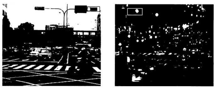
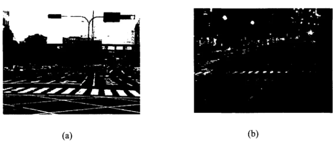
I ﹒~﹒ (b) Nighttime SceneFig. 1 : Typical scene examples at intersections, where traffic lights are bordered by rectangles, (a) Daytime Scene (b) Nighttime Scene.
2. System Architecture
The system architecture of the proposed automatictraffic light detection system at intersections is described in this section. It detects and outputs the state of the traffic light signals for other ITS applications. Typical scene examples at intersections are illustrated in Fig. 1,
where traffic lights are indicated in the rectangles, and Fig. l(a) is a daytime scene and Fig. l(b) is a nighttime scene. Some ITS applications could be issued after the traffic light conditions are known, such as taking a photo if somebody runs through the red light.
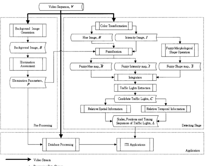
The block diagram of this system is depicted in Fig. 2, and it is constructed by two main stages: the
processing procedures inc1uding in these two stages are enc10sed by dashed rectangles as indicated in the figure. The input of this system is an outdoor video sequence, V,
which is composed by a sequence of continuous images. The output of it, L, is the detection result of the states of the traffic light. The result L inc1udes traffic light scales, positions, and timing sequence, which is ready for further processing. The thick arrows in the diagram represent the video streams, and the thin arrows are the data streams for the succeeding procedures. It should be addressed that a rectangle box is utilized to represent a processing procedure, and an arced-edge box is used pre-processing stage and detecting stage. The to show the output result after applying a method.
A Vision-Based Traffic Light Detection System at Intersections 71 Video Sequence. V ,---- --- --- --- -.- --- -- ---, De語ctißgStage ,自 I I A p p l i c a t i o n ~ Video Stream .. Processing Data Stream
Fig_ 2: The flowchart ofproposed automatic traffic light detection system at intersections
2.1
System setup and pre-processingThe hardware requirement of the proposed system is not restricted, but it is recommended to compose it with a DV-standard digital video camera and a conventional PC based computer in which a large amount of storage space is required when performing video recording continuously. Certain communication
the world is denoted as {眠,吭, Wz } _ Some physical
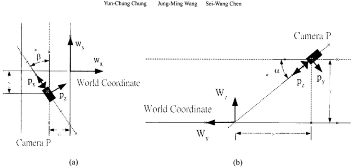
parameters are measured while installing the system for further processing, such as the height of the camera above the ground, h, the focal length,
f,
the inclination angle of the camera, α, the pan angle of the camera,ß
,etc. Performing a vision system in an outdoor environment is critical to illumination conditions. Background Image Generation and Illumination subsystems are considered necessary if it is required to Assessment procedures are employed in the integrate with other ITS components. The camera is pre-processing stage to provide necessary information to setup as Fig. 3 shown, where the coordinate of the further processing.
Sei-Wang Chen
:~有7
3;J
Jung-Ming Wang World C\ìordi 叭叭亡 4fy Yun-Chung Chung \Vorld Coordinatc Pz•-.1'\
Camèrar
w
Xw
72 (b)Fig. 3: The camera se仙p,the coordinate of the camera is denoted as {px, 抖,pz}, and the coordinate of the (a)
world is denoted as {吭,吭, r旬,(a) top司 iewof the camera (b) side句iewof the camera.
parameters, P, of the environment to those succeeding • Background Image Generation
The parameters P are also recorded with components
the input video stream for further database processing. To evaluate the current illumination condition, a
2.2 The detecting stage
background image, B, is necessa可 to avoid measuringThe background image generation procedure errors.
The detecting stage deals with the scene and there
(Ho叩rasert, Harwood and Davis, 2000; Long and Yang,
this stage, as are many sub-procedures inc1uded in
1990) produces the current background image, which
illustrated in Fig. 2: Color Information, Fuzzification,
foreground current to important reference provides Integration, Operation, Shape Morphological Fuzzy vehic1es as such applications ITS Other Image.
Traffic Light Extraction, Relative Spatial Information counting, vehic1es tracking can also take benefits of the
Notice that those and Relative Temporal Information.
background The
if applicable. Image
background
procedures or results can execute or obtain in parallel if image varies as time passes, thus it requires incessantIy
However, it is they are depicted as horizontal together.
updating.
not implemented in paralle1 here because the system
• I1lumination Assessment
All of them are brief1y actually performs very fast.
described in the following paragraphs.
It is important to evaluate the lighting condition
Traffic light detection outputs the red-yellow-green while taking vision-based processing in the outdoor
It first exams all light condition in time sequence.
open environments and this process is continuously
possible regions in the scene that may contain traffic updating the illumination condition while updating the
lights, and then chooses the best reference traffic light The position to construct the traffic light sequence. assessment illumination illumination the provide The employed to Image background IS procedure
A Vision-Based Traffic Light Detection System at Intersections 73
detection sequence of the traffic light is the red first, and then the yellow, finally the green. It is reasonable that detecting the red light first because that the red color is more distinguishable then the others, and due to the low brightness and contrast of the green light, it is detected at last. The position relations of the red-yellow-green light also help to detect the traffic lights. After the sequence has been established, the following ITS application can take advantage with it. Moreover, this stage works continuously and should not stop until shut down the system. The sub-procedures of the traffic light detection stage is briefly described as follows:
+Color Infonnation
The input video sequence V is composed with standard RGB color images, thus the first step of the detecting stage is to convert RGB image into HSI color model, i.e., the hue image, H, and intensity image, 1, for further processing.
+ Fuzzification
The hue image, H, and intensity image, 1, are fuzzifized with illumination parameters, P, to be the fuzzy hue map, H , and fuzzy intensity map, 1.
• Fuzzy Morphological Shape Operation
With the disk-like fuzzy morphological template,
morphology erosion and dilation operations are performed to eliminate noise and acquire all possible disk-like shape areas for the traffic light. A fuzzy shape map, S, is obtained after the operations.
+ Integration and Traffic Light Extraction The three fuzzy maps; 如zzy hue map, H; fuzzy intensity map, 1; and the fuzzy shape map, S; are integrated together. Then the traffic light extraction is operated on the integrated map to have the candidate
traffic lights, C.
+ Relative Spatial Infonnation
To eliminate the false detected traffic lights containing in C, the relative spatial information is very helpful. The traffic light contains red-yellow-green tricolor lights, which has fix relative spatial relationships.
+ Relative Temporal Infonnation
Besides relative spatial information, the temporal information is also useful to make confirmation on C to be the true traffic lights. After checking the spatial and temporal information, the most possible oftraffic light is obtained, and the scales, positions, and timing sequence oftraffic light, L, are obtained.
2.3
ApplicationsThe video sequence is employed for providing database of the legal evidence of violations. The system can also transfer information to other ITS applications. The procedures which may contain in the applications are video database recording with detected parameters, a red-light runner detection,
alphabet-number recognition oflicense plates, a zoom in view ofthe driver's face, coordinate transformation, and traffic parameters estimation, etc. Note that the extensions of these applications proposed here are our
臼tureresearch topics.
+ Video database recording with parameters Video recording with detected parameters offers legal evidence to issue a violation ticket, and the videotape/digital images can be used for other off-line processing or to verify the correctness of the system manually.
74 Yun-Chung Chung Jung-Ming Wang Sei-Wang Chen
• Red-light runner detection / Automatic to access the vehicle's data from the govemment's license plate recognition
Red-light runner detection is based on the information of the traffic light condition. Automatic license plate alphabet-number recognition is ve可 useful
database via network. It can notify policeman to intercept the vehicle immediately if any stolen car is detected. Furthermore, it can combine with the traffic ticket system to issue the ticket on-line.
3. Methodology
3.1
Color ModelsThe input of the system is a continuous traffic video sequence, which will first be separated to individual image frames for further processing. The image frames are composed with the RGB tri-color model and then converted into the HSI (Hue, Saturation,
and Intensity) color model (Gonzalez, and Woods, 1993).
It is well known that the hue value is uniform scaling and shifting invariance and it is also invariant to shadow and shading.
The components of HSI model can be transformed from the general camera RGB model using the following formulas (Gonzalez et al., 1993):
1= 伏+?)
S = 1 - 3 [ m i n ( R,G,B)], (1) (R+G+B)~[(R-G)+(R-B)]
I
H=
COS-I~ L. ~ 1.J
(R-G)2 +(R-B)(G-B)I
where R, G, B are the spectrums of the red, green, and blue components correspondingly.
Let the current input image at time is Ft, which contains the three components as shown in Eq. (2),
1
fH
,t(X
,
y) 1Ft= 兀 (X, y)=1
fs.t(x
,y) 1,I
fI.t(X
,y)I
(2)
where j; is the function of pixels, (x, y) denotes the spatial coordinates of the image, and the !H.t, fs.t, and fì.t are the hue, saturation, and intensity components correspondingly. Furthermore, it is important to define red, yellow, and green color models in advance because that the traffic light is composed by these three colors. The specific, red (Rt), yellow (其), and green (Gt), color
models are defined as:
R,
=
{g,(x,y) EF,
I [gH.,(X,y)[ <αH' and g/,(x, y) > α/ }, lTI Y,=
{g, (x, y) EF, IlgH
,,(X, y) 一一1<α們 andg/., (x,y) > α/ }, 1-"'<"" 31 , 2πl Gt = {g, (x, y) ε F, IlgH ,'(X,卅一一1<α H , andg/ ,,(x, y) >α/ }, 1-"'" 3 1 (3) where αH and αI are threshold values which may be determined by illumination conditions or manually glven.3.2
Background Image GenerationThis procedure creates the current background image, B. Obviously, the background image varies as time passing, thus it requires incessantly updating.
A Vision-Based Traffic Light Detection System at Intersections / / / / / /戶 I
I1 戶1(':
1 1:1:山~" I 1‘lI1k' I111 I1~b,'r( Jh.'érvdti廿土廿 Ia l'i\,'II'I\.\'1 dllll :l已 l II1,,'1
(a)
75
hlèn,ilY (\111nl 、
~h"t II\.'OU':I‘1 、,lI u,'
Il 可~~
, nlc 仁、 11\
lnlc:bitv (\、lIi,h I廿r1'1 XL'1 r、I X.V I 已 uril:.~tÎI11L' l"'('l"llìd I
、.•
','
,hu
/aE
、
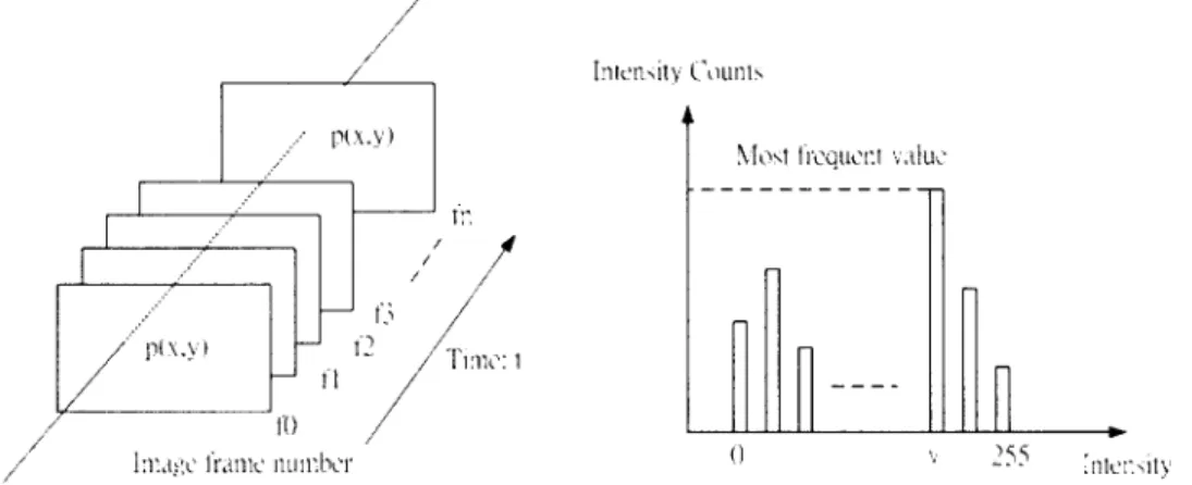
Fig. 4: The background value, v, of p is obtained from the most frequent values of
p(x, y) among the certain detection period, t. (a) The observation of pixel p舟, y)
during time t, (b) Intensity counts for pixel p(x, y) during time t.
However, the background image should not be changed radically, and basically it changes with the illumination condition changing (Long, and Yang, 1990). A fast background generation method is employed to generate and update background images. It is assumed that eve可 portionofthe background will become visible at some time. For every pixel, the fast background generation method will observe it for a certain period,
and then select the most frequent intensity values to be the background value. This method is very quick but it does not create a perfect background image. The background generated by this method may contain some obvious small noises, however, in this paper, these
obtained from the most frequent values of p among the certain detection period. In implementation, an intensity histogram is created to record the frequency of each intensity of p. This process is illustrated in Fig. 4,
and Fig. 4(a) is the observation of pixel p 妒, y) during time t, and Fig.4 (b) shows intensity counts histogram for pixelp 狀, y)during time t.
3.3
Illumination AssessmentsSome parameters in later procedures in the system are determined by the illumination condition. The illumination condition, P, is considered as two different types, daytime and nighttime. The illumination noises are not vital because they will not affect the next analysis is applied on the background images to avoid procedure, illumination analysis. the errors caused by vehicles or foreground objects.
The background generation algorithm is depicted Assume that the scene image containing N pixels, gÁ.x, as following: given a certain time period, t, for a pixel, p, y) is the intensity value of the pixel located at 恥, y) in which is located at 狀,y) in image frame
ft
of the inputvideo sequence, the background value, v, of p is
any frame
f
of the input video sequence. The illumination condition, p!> is determined by the76 Yun-Chung Chung Jung-Ming Wang Sei-Wang Chen
Table
1:
The states of a traffic light Redlight Yellow light GreenlightGO OFF OFF ON
RTS OFF ON OFF
STOP ON OFF OFF
|(R) 已) (G)| 于
O.5d O.5d 、‘,/ 曳 U J' 區、、7
1
7
。 5d (b) dFig. 5: A standard layout of a traffic light (a) Horizontal Layout (b) Vertical Layout
equations (4):
Pf=4ZEI(XJ)
N
(4)
It is determined as daytime if 只ris larger than certain threshold, otherwise, it will be nighttime.
3.4
The Traffic Light DetectionThe goal of this procedure is to construct a traffic light sequence by input video sequence automatically. A dimension sketch of a regular horizontal layout of the traffic light is illustrated at Fig. 5(a), and a vertical layout is shown in Fig. 5(b). Taiwan's traffic law (Ministry of Transportation and Communications and Ministry of the Interior, R.
o.
C. Govemment, 1994) restricts the standard layout and the lighting sequence ofTdITdI-jI
the traffic light in detail. Most traffic lights are horizontal layouts in Taiwan, thus the algorithm designed here is specialized to detect horizontal lights. However, if to detect a vertical layout traffic light is desired, the following algorithm can be easily adapted. By the design of the traffic light, the red (R), yellow (Y),
and green (G) lights all have the same diameter, d, and also the same distance, O.5d, between the two adjacent lights. The actual size of d is set to 30cm by Taiwan 's traffic law (Ministry of Transportation and Communications and Ministry of the Interior, R. O. C.
Govemment, 1994), which may be used as a scale reference. These position relations of the red-yellow-green light are helpful to detect them. The lighting sequence of the traffic light is also well-defined,
A Vision-Based Traffic Light Detection System at Intersections 77 μz I1h O 11 lr Intensity
h
m Hue (a) (b)Fig. 6: Membership Functions (a) Fuzzy Intensity μi (b) Fuzzy Hue μh
although the time period of lighting
“
ON" is variant at and the fuzzy hue functionμ'h is a Gaussian function each intersection, the sequence is invariant from GO .> whose mean, hm, is located at "red" color of the hueRTS (Ready To Stop) -> STOP and then back to GO, as scale, and its variance is ha. These fuzzy function illustrated in Table 1. parameters, Î/, În and ha, can be determined by The detection sequence of the traffic light is the red referencing the illumination condition. A fuzzy hue
“
ON" light fir哎, and then the yellow“
ON", finally the map, H , and a fuzzy intensity map, 1, are acquired green“
ON". The reason to detect the“
ON" red light from the fuzzification procedures.first is that the red color is more distinguishable then the Morphology erosion and dilation operations are others, and due to the low brightness and contrast of the then utilized to find out the shape information of the green light, it is detected after all. traffic light. The translation of a binary image A by a The system exams all possible regions in the scene pixel k is an image defined (Jain, Kasturi and Schunck,
that may contain traffic lights, and then chooses the best 1995) by reference traffic light position to construct the traffic
light sequence. The fuzzy membership functions are utilized to help locate the position. A fuzzy intensity
function ,州, and a fuzzy hue function , μ的 are employed to decide the possible regions belong to an
“
ON" redAk
=
{α +kl αε A} (6) The binary morphology dilation is then defined(Jain et 瓜, 1995) as a union of a binary image A by
A
tBB=
UA肉,
(7)b, εB
light, as illustrated in Fig. 6, where 1 is the number of binary image B = {bj, 缸, ..., bn}, and is given by
gray level. The fuzzy intensity function, μ, is defined where Abi is the translation of the binary image A by
re Jts qkm x<' 的 ', ι -Lao nv---1A x 一﹒ lr fl.-' , tttll4 ,《, }falli--tll 、 一一 、‘ B'/ x /',、、 μ (5)
the
“
1" pixels of the binarγimage B. Clearly,morphology dilation has both associative and commutative properties by this definition. The morphology erosion (Jain et 叫, 1995), the opposite of dilation, of a binary image A by a binary image B is“ 1"
78 Vun-Chung Chung Jung-Ming Wang Sei-Wang Chen 0.7 0.7 0.7 0.7 0.8 0.8 0.8 .07 0.7 0.8 0.9 0.9 0.9 0.8 0.7 0.7 0.8 0.9 1.0 0.9 0.8 0.7 0.7 0.8 0.9 0.9 0.9 0.8 0.7 0.7 0.8 0.8 0.8 0.7 0.7 0.7 0.7
Fig. 7: A 7x7 fuzzy morphology mask example
at a pixel k if and only if eve句“ 1" pixels in the
translation of B to k is also
“
1" in A. Symbolically,A Q9 B
=
{kI
Bk c A}, (8)and the binary image B is refe叮ed to as a structuring element.
The fuzzy morphology dilation and erosion operands are defined as extensions from these binary bases. Given a gray-levels image A = {al , 的, ...,。叫,
where ai is an integer and usually ranges from 0 to 255,
and also a fuzzy template B = {b I, 缸,..., b汁, where bi
ranges from 0 to 1 as fuzzy values. The fuzzy dilation unions the translation of ai of the image A by multiplying the template B with every relative bi, and
takes a normalization function after all translations are done. The result of the operation is a fuzzy image,
A
,and the equation is given by
立三 A否'B=IUAb
i
*bil
(9)b εB
The fuzzy morphology erosion, as the contrary operand, is defined for a pixel k of the image A to summarize the translation of the fuzzy template B to k,
and then normalize with the pixels number of Bk.
Symbolically,
IAb
i*b
iA三
A
面'B= {kl 肛品},
IBkl
(10)
where IBkl is the pixels number counting.
In our system, a disk like fuzzy morphology mask is applied. For example, a 7x7 mask illustrated in Fig. 7 can be used to extract the shape information. Thus,
the most possible
“
ON" red light is found by its shape information from fuzzy morphology, i.e., a fuzzy shape map, S, is obtained.Integrating the results of the three fuzzy maps: H ,
1 and S, a fuzzy map of belonging to an
“
ON" red light is obtained. A predefined threshold determined by P will be applied to the fuzzy map to obtain the candidate traffic lights, C. Ifthere is no “ON" red light found in the current 企ame, it will be dropped, and the system will proceed with next frame until at least an“
ON" red light is found. The d value is then obtained by this information.Next, with proper parameters setting, the
“
ON" yellow light can be found subsequently. Finally, withA Vtsion-Based Traffic Light Detection System at Intersections (a) 79 、‘, F LU , SE ‘、
Fig. 8: Background images of examples in Fig.l, (a) Daytime Scene (b) Nighttime Scene.
illumination information and the spatial relationships,
the
“
ON" green light can be easily detected.If there is more than one set of traffic lights detected, the one of the largest size is first selected for subsequence analysis. With the relative spatial and temporal information of the traffic lights, the scales,
positions
,
and timing sequences of traffic lights,
L,
wi11be determined. Note that the traffic light sequence must conform to the spatial and temporal limitations,
thus if the largest one does not, the second candidate will be tested again to ensure it is truly a traffic light.
To judge which light is current1y
“
ON", we needBR
= 土pI川
、‘.', •• 且-A
/S 圓、、yellow light
,
B y,
and the green light,
Bc,
are similar.Symbolical旬,
By
=
土耳的,川
(12)BG
=+'I g/
紗
,
y)
,
~G AG(13)
where A y is the size of the yellow light area, and Ac is the size of the green light area. We can then define the state of the red light as
“
ON" if the average brightness of the red area in current frame is higher than the half of average brightness, O.5BR. Otherwise, the state of the red light is“
OFF". The states of the yellow and green lights are defined as the same manners.After the sequence has been established, the pseudo the average brightness of it. The average brightness, connection between the traffic light controller and the
BR' for the red light first detected as
“
ON" is defined as: system is ready for use. Moreover, the current trafficwhere AR is the size of the red light area, and gÃx, y) light condition can be quickly retrieved and verified at
is the intensity value of the pixel located at缸
,
y)in any the detected area. The scale, and timing parameters are framejofthe input video sequence. also useful to other ITS applications, such as a red-light80 Yun-Chung Chung Jung-Ming Wang Sei-Wang Chen
Traffic Light Conditions 4 叫‘ J 司 J “ 的心】忍的 O 10 19 28 37 46 55 64 73 82 91 1 ∞ Frame Number
Fig. 9: The output sequence of 1Hz input frames of the detected traffic light conditions, where states 3 is STOP, state 2 is RTS, and state 1 is GO.
4. Experiment Results and Discussion
Some experimental trial is stated in this section. The input video streams are taken by a conventional DV camera, which contain 30 frames per second of 320 x 240 resolutions in NTSC based video system. Although it is possible to handle 30 frames per second,
it is not necessa可 to update the light conditions so fast in the traffic light detection system. The system
ac仙ally performs detection algorithm every 0.5-1.0 second, i.e., sampling at 1-2Hz rates, and skip all other unused input frames.
The pre-processing stage wi1l first obtain the background image, and the background images of the scene of Fig. 1 are shown in Fig. 8. Although the calculation of the background generation is ve可 fast, it must wait for all the background pixels show up. Thus,
it usually takes about several minutes to find the background image, and it will take longer time to initialize if the traffic is crowded in rush hours. The
daytime background example image shown in Fig. 8(a) is obtained from about 250 frames, and the nighttime background image shown in Fig. 8(b) is obtained from about 350 frames. It is not critical to obtain the perfect background image in traffic light detection because that the background image is only utilized to determine the illumination value in this system. However, if other applications are developing, such as red-light runner or vehicles counting, etc., the background image should be tuned up. The illumination parameter is then calculated to determine the environment condition which is daytime or nighttime.
The fuzzy hue map, H , and fuzzy intensity map,
1, are obtained from image frames with the predefined fuzzy functions. After applying the morphological operations, the three fuzzy maps;
“
zzy hue map, H;fuzzy intensity map, 1; and the fuzzy shape map, S;
A Vision-Based Tra飢c LightD刮目tionSystem at Intersections 81
Pba、e Phωe2
(a)
什斗扎什手 h
+
TWQ Ph山esCyc!e \Lert-ll1ll1 is prohiblltcd)
Pha紀 l Ph;l叫 J Pha心 1 Pha、'è .:\
(b)
Ht圳、~H 手 HHh
h.ur Phasö Cyclc
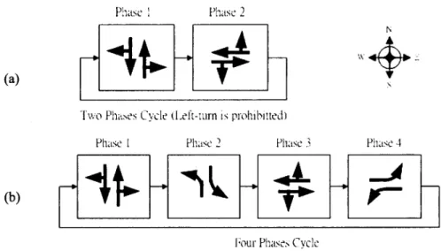
Fig. 10: Phases cycles oftraffic lights, (a)Two phases cycle, (b)Four phases cycle.
then obtained.
With the relative spatial and temporal information,
the scales, positions, and timing sequences of traffic lights are obtained. This system has been tested on outdoor complex scenes, with different illumination conditions and different camera angles. Fig. l(a)-daytime and Fig. l(b)-nighttime are two of the input examples.
An example of the output sequence of the detected traffic light conditions is in Fig. 9, where states 3 is
‘
STOP', state 2 is‘
RTS', and state 1 is‘
GO'. This output sequence is one of the nighttime sequences of sampling rate of one 企ameper second. In this example,it shows that the red light lasts about 24 seconds, green light continues about 20 seconds, and the yellow light goes about 2-3 seconds.
In our experiments, total six different intersections are tested, all including daytime and nighttime sequences. The traffic light detection results of them are verified manually and they are all proved correct.
These experiments demonstrate that this system performs ve可 good traffic light condition recognition and also robust to outdoor environments. Moreover,
the timing of the traffic light is obtained by the input frame timing, and it is useful to traffic control center to check out the timing for this intersection. If there is any problem of the traffic light, such as lights broken or timing eπor, the system can report this problem to the traffic control center right away.
In some environments, there will be more than one traffic light in the scene. The system will check for all candidate traffic lights, and decide the most reliable one to be the target. To avoid misrecognition of f1ashing neon advertisements or streetlamps, this decision is actually made after detecting all the sequences of traffic lights, i.e., to select one from the detected traffic light sequences. For example, there are two traffic lights and several small ones of the next intersection exists in Fig. 1 (b), and the system will detect at least two traffic light sequences (the small ones may be omitted due to the size limitation)
,
however,
the largest shape of the traffic light among the candidates wil1 be chosen by the system as the most reliable one. Note that in this case,it does not matter to choose either one of the two. On the other hand, the traffic lights have many different combinations and lighting sequences in
82 Yun-Chung Chung Jung-Ming Wang Sei-Wang Chen
Phases Traffic flow condi世on
(a) Phase 1 North-South s仕aightand right
turn
enabled Phase 2 Ease-West 咱也拉tand rightturn
enabled、‘自', LU /'、 Phases Phase
1
Phase2
Phase3
Phase4
Traffic flow condi世on
No吋1-S0U血甜aightand right
turn
enabled N orth-South leftturn
enabledEase-West s個ightand right
turn
enabled Ease-West leftturn
enabledFig. 11: Descriptions ofphases cycles, (a)Two phases cycle, (b)Four phases cycle.
practice (Ministry of Transportation and intersection, and it is shown in Fig. 1 O(b). The phases Communications and Ministry of the Interior, R. O. C. cycle ofthis traffic light is described in Fig. 11(6).
Government, 1994), such as combing with right-turn Although the phases cycles of traffic lights may only, left-turn only, or go-straight only, etc. These have many combinations, they have common layout:
special cases will be indicated by arrow green lights. one circular red light and one circular yellow light The lighting sequence of the traffic light of an combing with different arrow-type or circular-type green intersection can be describe as a phases cycle, and the light(s). Recall that our system detects red lights first phase time is determined by the traffic signal control (the most reliable feature), and then the yellow lights,
box, or manually by traffic police officers. and finally the green lights. These arrow-type green A standard two phases cycle (left-turn prohibited), lights are also limited by the spatial and temporal which is controlled by a red-yellow-green tri-color relationships of red and yellow lights. Thus these traffic light, can be depicted as Fig. lO(a). The phases phases cycles can also be detected by modifying the cycle of this traffic light is described in Fig. ll(a). circular green light template with an arrow-like Moreover, a four phases cycle traffic light is ve可 morphologicaltemplate.
common and can easily be seen in a left-turn enabled
5. Concluding Remarks and Future Researches
In this paper, an automatic traffic light detection generates background images and also illumination system at intersections is presented. From experiment parameters. The HSI color model is then employed,
results, it shows that it is validated to perform traffic and fuzzy methods and morphological technique are light detection on traffic videos without any signals utilized together to find the candidate traffic light areas. from the traffic light controllers. The system With the relative spatial and temporal information, the architecture is brief1y described as follows: it first scales, positions, and timing sequences of traffic lights
A Vision-Based Traffic Light Detection System at Intersections 83
are acquired.
An automatic traffic light detection system at intersections is one of the key components of the vision traffic enforcement system, such as red light runner
detecti嗯, tuming against traffic lig恤, and stopping at the non-stopping zone. Next, we will try to design a vision traffic law enforcement system integrated with the traffic light detection system; moreover, with the changeable outdoor environments and different setup conditions of the vision system, the system must be robust to weather and illumination conditions, and also tolerant to various perspective angles. This new system is currently under developing.
as: volume, speed, occupancy and concentration, etc.
It can be customized to show the driver's face or take a zoomed close up photo of his/her license plate if
necessa可﹒It can also generate traffic citations showing clear digitized photographs of eve可 vehicle
committing an offense, as well as detailed statistical reports which may be a histogram of average vehicle counts over a time period, or including the total vehicle count, speed profiles, and violation profiles. Those information can be integrated with other ITS components to provide road users on demand information. The real time information is ve可
valuable, and it may propagate via any distribution For the further researching, it is suggested that the device such as Intemet, in-vehicle satellite navigation vision traffic enforcement system can be designed in devices, wireless media, or traditional radio and TV advanced to provide more traffic data parameters, such broadcasts.
84 Yun-Chung Chung Jung-Ming Wang Sei-Wang Cher>
Reference
8eymer, David; McLauchlan, Phìl 巾;Coifman, 8enn, and Malìk、 Jitendra (1997), '‘A Real-time Computer Vision System For Measuring Traffic Parameters," Proceedings of JEEE Computer Society Conference on Computer Vision and Pattern Recognition, pp.495-50 1, San Juan
Dariush, 8. and Fujimura, K. (1999), “A Framework for Driver Specific Inference of Danger at Signalized Intersections,"
JEEE Jnternational Conference on Intelligent Transportation 度ystems,pg. 195-200, Tokyo, Japan, Oct 1999
Dickinson, K. W. and Wan, C. L. (1989), “Road traffic monitoring using the TRIP II system," Second International c。可的nceon Road Traffic Monitori嗯, pp.56-60, London, UK, February 1989.
Gonzalez, Rafael C. and Woods, Richard E. (1993), “Digital Jmage Processing," New York, US: Addison-Wesley Publishing Co., pp. 229-237
Ho叩rase此,Thanarat; Harwood, David and Davis, Larry S. (2000),
“A Robust 8ackground Subtraction and Shadow Detection," in Proceedings ofthe Fourth Asian Conference on Computer Vision, pp.983-988, Taipei, Taiwan, January 8-11,2000. Institute of Transportation, Taiwan, R. O. C. Govemment (2002),
Web Documents - “Intellìgent Transportation Systems,"
April 2002. (http://www.iot.gov.twlits/)
Jain, R.; Kasturi, R. and Schunck, 8. G. (1995), “Machine Vision," McGraw-Hill Intemational Editions, pp. 61-70, New York, US.
Jung, Y.-K. and Ho, Y.-S. (1999), “Traffic parameter extraction using video-based vehicle tracking," Proceedings of JEEE/JEEJ/JSAJ International Conference on Jntelligent Transportation 砂stems, pp.764 -769, Tokyo, Japan, Oct 1999
Kl 汀, George 1. and Yuan, 80 (1995), “Fuzzy Sets and Fuz砂 Logic Theory and Applications," London, UK Prentice-Hall Inc.
Lai, Andrew H. S. and Yung, Nelson H. C. (1998), “A Video-8ased System Methodology for Detecting Red Light Runners," in Proceeding of JAPR Workshop on Machine Vision Applications, Chiba, Japan, pp.23-26, Nov., 1998. Long, Warren and Yang, Yee-Hong (1990), “Stationary
8ackground Generation: an A1temative to the Difference of Two Images," Paltern Recognition, Vo1. 23, No. 12, pp.1351-1359.
Matsushi泊, Yasuyuki; Kamijo, Shunsuke; Ikeuchi, Katsushi and Sakauchi, Masao (2000), “Image Processing 8ased lncident Detection at Intersections," in Proceedings of the Fourth Asian Conference on Computer Vision, pp.520-527, Taipei,
Taiwan, January 8-11, 2000
Ministry of Transportation and Communications and Ministry of the Interior, R. O. C. Govemment (1994), '‘Official Rules of
Road Traffic Signs, Traffic Marks and Traffic Lights (道路
交通標誌標線號誌設置規則)",July 1994.
Naumann, R.; Rasche, R. and Tack凹, 1. (1998), “Managing Autonomous Vehicles at Intersections," JEEE Jntelligent Systems, Vol. 13, No. 3, pp. 82-86, June 1998
Palmer, David A.; Mellerio, John and Cutler, Amanda (1997),
“Traffic Signal Light Detection through Sunglare Filters of Different Q Factors," Color Research & Application,
22:24-31.
The department of statistics of the Ministry of Transpo巾tionand Communications (MOTC) of Taiwan, R. O. C. Govemment (2002), Web Documents of Statistics data, April 2002 (http://www.motc.gov.tw/servicelindex.htm)
U.S. Department of Transportation, U. S. A. Govemment (2002), Web Documents, April 2002. (http://www.dot.gov)
Wixson, L.; Hanna, K. and Mish悶, D. (1998), “lmproved IIIumination Assessment for Vision-based Traffic Monitoring," JEEE Workshop on Visual Surveillance,
pp.34-41, 80mbay, India, 2 January, 1998
About the Authors
Yun-Chung Chung received the B.E. degree in naval architecture and ocean engineering from National Taiwan University, Taipei, Taiwan, R.O.C., in 1993, and the M.E. degree in information and computer education from National Taiwan Normal University, Taipei, Taiwan, in 1995. He is currently pursuing the Ph.D. degree in the department of information and computer education, National Taiwan Normal University.
From 1997 to 1998, he worked as an Associate Engineer in Information Science and Technology Exhibition Center, Institute for Information Industry, Taipei, Taiwan. His research interests include traffic monitoring system, visual tracking and surveillance and digital image processing.
Jung-Ming Wang received the B.E. degree in information and computer education from National Taiwan Normal University, Taip缸, Taiwan, R.O.C., in 1996. He is current1y pursuing the M.E. degree in the department of information and computer education, National Taiwan Normal University. His research interests inc1ude digital image processing pattem recognition and computer vision
Sei-Wang Chen received the B.Sc. degree in atmospheric and space physics, the M.Sc. degree in geophysics from National Central University in 1974 and 1976, respectively, and the M.Sc. and Ph.D. degrees in
AVi 日 on-BasedTraffic Light Detection System at Intersections 85 computer science from Michigan State Universi旬, East
Lansing, Michigan, in 1985 and 1989, respective1y.
From 1977 to 1983, he worked as a Research Assistant in the Computer Center of Centra1 Weather Bureau, Republic of China. In 1990, he was a researcher in the Advanced Techn010gy Center of the Computer and Communication Laboratories at the Industria1 Techn010gy Research Institute. From 1991 to 1994 and from 1995 to 2001, he was an associated professor and full professor of the Department of Information and Computer Education at the National Taiwan Normal Universi紗,Taipei, Taiwan,
*
AcknowledgementRepublic of China, respectively. He is currently a professor of the Graduate Institute of Computer Science and Information Engineering at the same University. His areas of research interest inc1ude neural networks, fuzzy systems,
pattem recognition, image processing and computer vision Manuscript Received March 18, 2002
Revised March 28, 2002 Accepted April 16,2002
This work is supported in part by the National Science Council, Taiwan, Republic of China under contract NSC90-2213-E-003-001
86 Yun-Chung Chung Jung-Ming Wang Se卜 WangChen