Analysis and Architecture Design of EBCOT for JPEG-2000
Kiian-Fii Chen, Cluing-Jr Lian and Hong-Hili Chen, Liang-Gee Chen
Department of Electrical Engineering, National Taiwan University
1, Sec.4, Roosevelt Road, Taipei 106, Taiwan
10.81 71.63 14 89 1 0 8 5 26 14 19 75 17.56
ABSTRACT
26.38 11.9 23.97 6.42 5.04 52.26 69.29 43.85 14 82 13 9 12 39 7 10 94 5 63 16 09 25 12 13 77 14 35 19 33 12 06 14.95 17.9 13.01This paper presents detailed analysis and efficient architecture design of Embedded Block Coding with Optimized Truncation (EBCOT) for PEG-2000. Detailed profile of the context formation process in EBCOT is analyzed to get an insight into the character- istics of the operation. Column-based operation is adopted to enable higher process speed. Two speed-up methods, referred to as Pixel Skipping (PS), and Group-Of-Column Skipping (GOCS), are proposed. It is shown that over 60% of processing time can be reduced by exploiting the two methods. A column-based architec- ture using these combined speed-up ideas is then proposed.
10
7.56
1.
INTRODUCTION
9.52 9.94 7.95 5.43 7.96 . 5.06
PEG-2000 [ 1][2][3] is an emerging standard for still image com- pression. It not only has better compression perfonnance than the existing P E G [7] standard but also provides new features not
available in P E G . PEG-2000 is composed of two parts: Discrete Wavelet Transfonn (DWT) and EBCOT, as shown in Fig. 1.
Wavelet transform is a subband transfonn, and it transfers images
from spatial domain to frequency domain. The generated coeffi- cients are then scalar quantized and entropy coded by EBCOT.
, __. . . .. . , . . . .. . . , . . .. . . ... . . ... . .
_.
Fig. 1. PEG-2000 block diagram
EBCOT coding algorithm is proposed by David Taubman [4][5] [6]. It contains two parts, tier-I and tier-2, as shown in Fig. 1. Tier- 1 is a complete context-based arithmetic encoder. It divides quan-
tized subbands composed of wavelet coefficients into code blocks, and encodes code blocks into independent embedded bit-streams. Tier-2 orders the bit-streams into final JPEG-2000 format bit- stream according to rate-distortion values calculated by tier-1 and features specified by user. As we can see in the run time profile of JPEG-2000 in Table I, the great part of computation load is on tier- 1 coder.
In this paper, we aim our focus and analysis on Tier-I coder and propose architecture for this part. Our analysis of EBCOT is presented in Section 2, which details profiles and analysis of the EBCOT Tier-1 coder. Two speed-up methods are proposed ac- cording to the analysis results. The proposed architecture exploit- ing these speed-up ideas is described in Section 3. Experiment results on different images are given in Section 4. A short conclu- sion is given in Section 5 .
Table I. Run time profile for PEG-2000 (Image 1792x1200, 5 level wavelet decomposition, 1 layer, profile at PIII-733 128M RAM, Visual C t t 6.0 and Windows ME)
Operation Intercomponent transfonn lntracomponent transfonn quantization EBCOT Tier 1 pass 1 pass 2 pass 3 arithmetic encoder layer formation marker insertion EBCOT Tier 2
Single Component I 3 Components(RG0) Lossless I LOSSY 1 Lossless 1 LOSSY
I I 0.91 I 14.12
2.
EBCOT ALGORITHM AND ANALYSIS
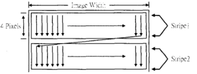
Tier- 1 of EBCOT utilizes context-based. arithmetic coding method to encode each code block into independent embedded bit-stream. Tier-1 coder can be viewed as two parts: Context Formation (CF) and Arithmetic Encoder (AE). CF scans all pixels in code block in a specific order, and generates corresponding contexts for each bit. AE encodes the code block data according to their. contexts. EBCOT encodes the quantized wavelet coeficients bitplane by bitplane from MSB to LSB. Eveiy 4 rows in a bitplane are called a “stripe,” and each pass in every bitplane scans in order stripe by stripe. Then in every stripe, data are scanned column by coluinn. Every column is composed of 4 bits. So the scanning hierarchy of a code block is bitplane, pass, stripe, column, bit, as shown in Fig. 2.
Pixci
3
3
Siripc is
! I_i pc 2Fig. 2. Scanning order of context formation in every pass Contexts for all bits are generated according to their neighbors
using four coding methods. Before CF, the quantized wavelet coefficients are separated into sign and magnitude (in 1‘s compli- ment). A pixel is called “significant” after the first ‘ 1 ‘ bit is met while encoding magnitude part from MSB to LSB, and “insignifi- cant” before the first ‘ 1 ’ bit appears. The context of each bit is determined by significant situations of its neighbors. There are four coding methods to generate context for each bit in a code block: Zero Coding, Run-Length Coding, Sign Coding, and Magnitude Refinement.
0-7803-6685-9/01 I$ IO.000200 1
IEEE
Every bitplane is encoded using 3 passes in turn. Each pixel in a bitplane is encoded in one of 3 passes. Pass 1 is “Significant Propagation Pass.” Pixels having at least one significant neighbor are coded in this pass. Pass 2 is “Magnitude-Refinement Pass.” All significant pixels are coded in this pass. Pass 3 is “Clean-up Pass.” Pixels not coded in first two passes are coded in this pass. While coding a bitplane, every pixel is checked once in all 3 passes to detennine if this pixel should be coded. In Taubman’s architecture, a straightforward method is used. Every single bit is checked and (or) coded in all 3 passes, which cost total 3 clocks. Coding a 64x64 code block with 8-bit precision will take 6 4 x 6 4 ~ 8 ~ 3 clocks. That makes tier- 1 coder become bottleneck of PEG-2000 system design.
6-e
SignificantBecome Significant Neighbor
Fig. 3. Evolution Map: higher bitplanes to lower bitplanes
According to the characteristic of the context formation process, great improvement on process time can be achieved. Every pixel is insignificant at the beginning of coding first bitplane (Most Sig- nificant Bitplane), so all pixels are coded in pass 3. As we coding toward lower bitplanes, some pixels become significant. They will be coded in pass 2, and their insignificant neighbors will be coded in pass I , as shown in Fig. 3.
Pixel No.
:::
( 0
R I1
MSB L S B
Fig. 4. Pixel distribution in 3 passes
The characteristic of the context fomiation process makes the distribution of pixels in 3 passes vary greatly from bitplane to bitplane. A real case is analyzed and the result is shown in Fig. 4. It is an 8x8 LL subband (lowest frequency subband) from 256x256 Lena image with 5-level wavelet decomposition. I n highest bit-
plane (MSB), all pixels are coded in pass 3. However. in lower bitplane (near LSB), most pixels are coded in pass 7, only few pixels are coded in pass I , and non in pass 3. The number of pixels coded in pass 1 increases at the beginning, and then decreases because more and more pixels coded in pass I become significant, Every pass spends the same time in the architecture in [3], but some passes do not even encode a single pixel (such as pass 3 in bitplane 0-3). We make a great improvement on process time utilize distribution variation feature. and will be discussed later.
2.1 Column-Based Operation
Higher speed and data reuse can be achieved via column-based operation. In Taubman’s architecture [3], data are supplied to context formation element one pixel at a time. We speed-up con- text formation by processing more than one pixel every clock. In the proposed architecture, column-based operation is adopted instead of pixel-based operation. Data are supplied to context formation element one coluinti (four pixels) at a time. There are two advantages of column-based operation: 1 ) pixels in a column can be checked simultaneously, so speed-up methods proposed can be applied. 2) Higher data reuse in significant and sign state vari- ables. Memory access frequency of these state variables can be reduced.
2.2 Two Speed-up Meth,ods
Table 11. Columns classified by number of NBC pixels con- tained (Baboon, 5 12x5 12,S-Ievel wavelet, code block 64x64)
-
NBC
11
number of column in each IDass -I
Pass1
1
Pass2I
pass3I
Sum1810761 15922312583281 598627147.85%
-
In every bitplane, each pixel is coded in one of 3 passes, so one column in every pass may contain 0-4 Need-to-Be-Coded (NBC) pixels. Table I1 shows the analyijis results of column-based opera- tion. Columns are classified in every pass according to number of NBC pixels in them. For example, there are I81076 columns contain zero NBC pixels in pass 1, 159223 columns in pass 2, and 258328 columns in pass 3. There are in total 598627 (47%) col-
uinns contain 0 NBC pixels. The percentage of coluinns having four NBC pixels (which means no processing time is wasted in Taubman’s architecture [3]) is only 22.06%. According to Taub- man’s architecture, coding a column costs 4 clocks no matter how many NBC pixels are in it. The key ideas to improve the process speed are: ( 1 )skip no-operation pixels, and (2)skip no-operation coluinns (columns with zero NBC pixel). These ideas are described below:
1) Pixel Skipping (PS): PS is designed for all 3 passes, which skips no-operation pixels in a colunm. By column-based coding, pixels in a column can be parallel checked to see if they are NBC pixels. Only NBC pixels are processed, other no- operation pixels are skipped. If there are n NBC pixels in a col- umn(0 -< n -: 4), only n clocks will be spent on coding these NJ3C pixels, and 4-11 clocks are saved. Since most columns have less than 4 NBC pixels, this method can improve system process speed greatly, as the experimental results shown in Sec. 4.
2) Group-Of-Column Skipping (GOCS) : GOCS skips a group of no-operation columns together in pass 2 and pass 3. By using PS speed-up methods, every no-operation colu~nn will cost only 1 clock for checking. To further improve process speed, these no-operation coluinns should be skipped. Due to the prop- erty of wavelet transfonn, spatial correlation between wavelet
coefficients is strong, so no-operation columns usually group together. We choose every S consecutive columns as a GOC. If there is no any column in this GOC to be a NBC column, this GOC is directly skipped, which can save 31 clocks compare to Taubman's design. GOCS can only applied on pass 2 and pass 3, because of the significant propagation in pass 1. So regular cod- ing is applied to pass 1, that is, columns are checked one by one. After coding pass 1, all NBC columns of pass 2 and pass 3 are decided. The GOCs that contain NBC columns are recorded. While encoding pass 2 and pass 3, only those GOCs contain NBC columns are processed and all no-operation GOCs are skipped.
Every single method can improve processing speed, and each can be used together or separately. The percentage of improvement is given in Section 4.
3.
ARCHITECTURE
An efficient column-based context formation architecture for tier-] coder is described in this Section. The key ideas are based on the column-based operation and two speed-up methods described above.
Fig. 5. Tier- 1 context formation system block diagram
I n Fig.5. code block nzerlior?~ stores the whole block data in a sign and magnitude separation manner. Starc I'ariablc Me/norics are used for storing three different kinds of state variables (significant, magnitude refinement, final) necessary for context formation. These state variables corresponding to current coding column are then sent to Stote Var-ioble PE. After some operation in State
C'rri-iob/e PE, variables needed for 4 coding PE are generated. Sign
Mogiiitirclc PE works similar to Stare Variable PE. Four coding
PES can generate contexts according to the state variables, sign and magnitude. Three Pass Colitrollers control four codirig PES and select the output contexts.
3.2
Column-Based Operation
The key point to applying column-based operation is to solve memory airangement and access for significant and sign variables.
For coding a single bit, we need 9 significant state variables and 9
sign variables (variables of self pixel and 8 neighboring pixels). I n a column-based design, 18 significant and sign variables are needed at the same time, including cin'l'eiit and two neighboring
columns, 6 bits each, as shown in Fig. 6 . Since variables from neighboring stripes are needed, it is quite a challenge to arrange and access memory. For example, if significant state variables are stored in a memory, 1 column within a stripe (4 bits) as a word, then every time a new column is processed, 3 words must be loaded from memory, which will take 3 clocks. Besides, more than needed data are loaded. Only 6 more variables are needed for coding a new column, but 12 variables are accessed.
This problem can be solved by using three smaller memories, and set 2 bits as a word. As shown in Fig. 6 , variables of different row are interleaving placed in 3 memories (A, B, C, B, A, B .... ). By this arrangement, variables needed for processing a new column can be accessed at the same time. In a situation of continuous
coding, after finish coding one column, we just shift the significant state variables in register array to left, and load one new column into right side of this array.
C'..11c:-.
COL::!! p:xc.s
Fro::. .Llc::ory
.A
41c::ory
B
41c::ory
c
Fig. 6. Significant and sign variable registers
Fig. 7 is the architecture for significaizt state variobles PE. It can provide not only the significant state variables needed, but also the sum of significant neighbors of each pixel in current coding col-
umn simultaneously. The architecture for sign iiarinbles PE are
similar to Fig. 7 , except one small converting circuit is used in- stead of these adders. The converting circuit converts sign vari- ables of neighboring pixels into H,V contributions needed by Sign Coding PE.
V I H I
v 2 H2
v 3 H3
v4 H4
Fig. 7. First 3 columns of sigrzi'jicaiit state variable PE
3.3
Pixel Skipping
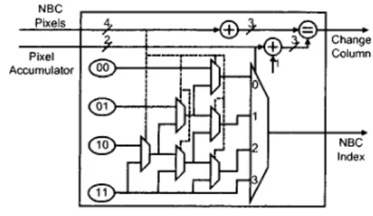
To implement pixel skipping method, indexes for NBC pixels in this column must be generated one by one. The architecture for pixel skipping is shown in Fig. S. A 4-bit bus indicates if pixels in
current coding column are NBC pixels or not. The pixel accumula- tor counts the number of pixels (0-3) already coded in this column. The index of current coding pixel is generated, then the pixel accumulator is compared with the number of NBC pixels. If all NBC pixels in this column are coded, a change column signal is generated. By this architecture, all no-operation pixels can be skipped with only a little hardware cost.
Taubman’s NBC Pixels Pixel Accumulator 130
I
1-31 364 x l O k cyclesFig. 8. Pixel skipping architecture
3.4
Group-Of-Column Skipping
Group-Of-Column skipping is applied on pass 2 and pass 3. Every 8 consecutive columns are group together as a GOC. All no-
operation GOCs in these two passes can be skipped. Since the condition (NBC or not) of all GOCs in pass 2 and pass 3 must be recorded in pass 1 coding, a memory for storing the conditions of
all GOCs is required. I n a general case with code block size 64x61, a small memory of size 64x4 is needed (128 GOCs for each pass).
3.5
System Specifications
The design for EBCOT tier-1 coder, which includes context fonna- tion and arithmetic encoder, is finished and taped out. Tables I11 shows the detail specifications of this design. Note that most of the memories are necessary for EBCOT algorithm, and only 2S6-bit extra memory are required for proposed speed-up method.
Table 111. Specifications of EBCOT tier-1 coder system )Process Technoloav I,I , 0.35um CMOS 1P4M
1
Chip Size
I
3.67x3.67 pm2I
I
21 000 gates + 13 kbit memory Gate Count Clock Freauencv I 50 MHz lsupply VoltageI
3.3v
I
Power ConsumptionI
11 5.49 PackageI
144 CQFP4.
EXPERIMENT
RESULTS
Experiments are made on encoding various images with proposed architecture and Taubman’s [3] for comparison. The processing time ofcontext formation in tier-I coder is shown in Table IV. It is clear that the performance improved dramatically, with more than 60% of improvement in all cases. A detail result that shows the processing time of every passes is shown in Fig. 9. In the circum- stances that only PS is applied, the processing time is reduced to
43% compared with Taubman’s architecture. By using PS+GOCS, processing time can be fiirther reduced to 37%.
Table IV. Experimental results for processing time of pro- posed architecture compared with David Taubman‘s, on 4 different images with size 5 12x5 12, 2 kinds of filters
PS
mi,
158;IOk cycles (43 4%)I l l i
CS+PS m l ‘ 1 3 7xlOk cycles (37.6%)
Fig. 9. Experimental results on detail processing time of
every passes, with image ‘Lena’ and 917 filter
5. CONCLUSIONS
In this paper, analysis and architecture design of tier-1 coder of EBCOT for PEG-2000 is presented. Column-based coding archi- tecture with two speed-up methods, Pixel Skipping, and Group-Of- Column Skipping are proposed according to the characteristic of EBCOT algorithm. These two methods can improve the efficiency of the iinpleinentation to more than 60%.
6.
REFE.RENCES
[ I ] JPEG-2000 Port I Fiizol Continittee Droj Version I.0,
ISO1IEC JTC 1/SC29/WG1 N 1646R.
[2] M. D. Adams, F. Kossentini (UBC),H. Man (SIT), T. Ebra- himi (EPFL), JPEG-2000: The Nest Generotion Still 1moge Cornppr-ession Stmidord, ISOiIEC JTC l1SC 29/WG 1N1734. [3] C. Cllristopoulos, MediaLab, Ericsson Research, Sweden,
JPEG-2000 Verificotioii Model 7.0 (Teclinicul description), IS01IEC JTC l1SC 29/WG I N 1684, Apr. 3000.
[4] D. Taubman, EBCOT: Eiitbedded Block Codirig ivith Opti-
nzized Tmitcotioiz. ISO1IEC JTC IISC291WG 1 N 1020R. [SI D. Taubman, High Peifor~iiorzce Scoloblc Iiitoge Coiripr-cssiort
With EBCOT, Proc. of IEEE International Conference on Im-
age Processing, Kobe, Japan. 1999, vol. 3, pp. 344-348.
D. Taubinan, Eiiibcclded Block Codirig in JPEG-2000, Proc. of IEEE International Confe.rence on Image Processing, Van-
couver, Canada, 2000, vol. 2 , pp. 33-36.
[7] W. Peruiebaker and J. Mitchell, JPEG Still Imoge Coiiipres-
sioii Storidol-d, New York: Van Nostrand Reinhold, 1993. [6]