Video-Based Early Flame Detection for Vessels by Using the Fuzzy Color Clustering Algorithm
6
0
0
全文
(2) gasoline, and diesel fuel, respectively. The early firing images are depicted in (a1), (a3), (b1), (b3), (c1), (c3), (d1), (d3), (e1), and (e3). The fully firing images are described in (a2), (a4), (b2), (b4), (c2), (c4), (d2), (d4), (e2), and (e4).. selection phase, and the fuzzy color clustering phase. Detail processes are described as follows: Video Sequences. Frame Selection Phase. Region Selection Phase. Fuzzy Color Clustering Phase. DFCLTs. Fig. 1. The creation process of the DFCLT.. 2.2: REGION SELECTION PHASE. 2.1: FRAME SELECTION PHASE. To acquire the fire pixels precisely, fire regions are manually cropped as shown in Fig. 2 (r1), (r2),…, and (r20). We obtain 321,435 fire pixels to create the DFCLT.. An early firing image and a fully firing image are selected from each video sequence. Therefore, twenty images are manually selected from the aforementioned ten video sequences. As shown in Fig. 2, (a), (b), (c), (d), and (e) are the firing images of paper, sawdust, pillows,. (a1). (r1). (a2). (r2). (a3). (r3). (a4). (r4). (r7). (b4). (r8). (a). (b1). (r5). (c1). (r9). (b2). (c2). (r6) (b). (b3). (r10). (c3). (r11). (c4). (r12). (d3). (r15). (d4). (r16). (e4). (r20). (c). (d1). (r13). (d2). (r14) (d). (e1). (r17). (e2). (r18). (e3) (r19) (e) Fig. 2. The firing images and regions of (a)paper (b)sawdust (c)pillows (d)gasoline (e)diesel fuel.. 2.3: FUZZY COLOR CLUSTERING PHASE. algorithm is given as follows:. In this phase, the fuzzy c-means (FCM) algorithm is used to group pixels into clusters [9] according to RGB color features. The FCM_based clustering procedure iteratively minimizes the criterion function as shown in (A1). A detailed description of the clustering. The FCM Clustering Procedure // The input values are RGB color features. // The output values are clusters with pixels. // c represents the number of clusters, w the exponential weight, and. - 1180 -.
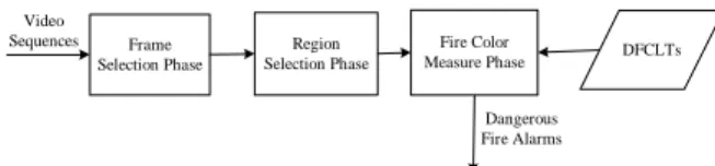
(3) //µik ‘s (i=1,…,c, k=1,…,n) the membership values 1 Initialize parameters c and w; and then assign values to µik ‘s using either a random function or an approximation method. 2 Do 3 For each cluster c, update center using (A3) and 4 µik ‘s using (A2); 5 Until (all centers are stabilized) 6 Assign pixels to one cluster according to µik’s. In the simulation, w is 1.5, and c is set from 5 to 12. To distinguish the elementary, medium, or emergency fire-alarm, and to concern the computational complexity, five clusters (i.e. dominant fire colors) are accommodated to the proposed method. Table 1 demonstrates the DFCLT for vessels. Table 1. The DFCLT for vessels.. 3.2: REGION SELECTION PHASE In this phase, regions are segmented according to the selected binary images by using 8-adjacency connected components. We inspect each pixel of the binary image with value 1 by using 8-adjacency connected components from left to right, top to bottom. The changed regions are segmented as show in Fig. 4. Finally, the fire pixels of each region are obtained by the convolution of segmented binary image and selected image. 0 0 1 1 1 1 1 0. 1 1 1 1 1 1 1 0. 0 0 1 1 1 0 0 0. 0 0 0 0 1 0 0 1. 0 1 1 0 0 0 1 1. 1 1 1 1 1 0 1 1. 0 0 0 0 1 0 1 1. 0 0 1 0 1 0 1 0. 1 1 1 1 0 0 0 0. 1 1 1 0 0 0 0 0. 0 0 a a a a a 0. a a a a a a a 0. 0 0 a a a 0 0 0. 0 0 0 0 a 0 0 d. 0 b b 0 0 0 d d. b b b b b 0 d d. 0 0 0 0 b 0 d d. 0 0 c 0 b 0 d 0. c c c c 0 0 0 0. c c c 0 0 0 0 0. 0 0 a a a a a 0. a a a a a a a 0. 0 0 a a a 0 0 0. 0 0 0 0 a 0 0 d. 0 b b 0 0 0 d d. b b b b b 0 d d. 0 0 0 0 b 0 d d. 0 0 b 0 b 0 d 0. b b b b 0 0 0 0. b b b 0 0 0 0 0. Fig. 4. The example of region segmentation.. 3.3: FIRE COLOR MEASURE PHASE. 3: THE DANGEROUS DETECTION. FLAME. Fig. 3 shows the process of the proposed dangerous flame detection approach. First, the changed video frames are automatically selected. Then, the changed regions are figured out from these frames. Finally, we announce elementary, medium, or emergency dangerous flames by comparing the pixels of changed regions with the DFCLT. Detail processes are described as follows: Video Sequences. Frame Selection Phase. Region Selection Phase. Fire Color Measure Phase. DFCLTs. Dangerous Fire Alarms. We announce elementary, medium, or emergency dangerous flames by comparing the pixels of changed regions with the DFCLT. If the pixels of region belong to less than and equal to two dominant flame colors, non-flame alarm is issued for the region, e.g., the flame of lighter or candle. If the pixels of region belong to 3, 4, or 5 dominant flame colors, the elementary, medium, or emergency flame alarm is issued for the region, respectively. There are two steps to decide whether the pixel is belongs to the DFCLT. First, pixel is temporarily assigned to one dominant color of DFCLT where the Euclidean distance between pixels of selected region and the dominant color of DFCLT is minimum as shown in (1), and the pixel is in the range of the dominant color. The range of each dominant color is computed as a circle where the center is 2 2 2 (1) D (Qi , I ) = (QRi − I Rj ) + (QGi − I Gj ) + (QBi + I Bj ) i. Fig. 3. The process of dangerous flame detection.. 3.1: FRAME SELECTION PHASE The luminance of video frames is increasing from non-flame to flame alarms issued. First, all video frames are converted to gray level images, and a smoothing filter is used for noise reduction. Second, a non-flame image is assigned to the reference image (I0), and difference images (ID1, ID2,…) are obtained from the subtraction of consecutive images (I1, I2,…) and the reference image. Then, difference images are converted to binary images where 1 represents the pixel of changed region, and 0 represents the pixel of background. Finally, changed images are selected while the pixel number (PN) of 1 is greater than the threshold value of Ta. The experimental value of Ta is 25 pixels.. j. where Ij={Rj,Gj,Bj},j=1,2,…,n, is the pixels of selected region, Qi={Ri,Gi,Bi}, i=1,2,3,4,5, the values of the DFCLT. Second, we check the assigned pixel whether it is in the range of the dominant flame color. The range of each dominant color is computed as a circle where the center (di) is the dominant flame color, and the radius (Rmi) is the distance between the color of pixel and center. As shown in Fig. 5, though the sample pixel is near the fifth dominate flame color, it does not belong to any dominate flame color of the DFCLT for the reason of out of range of all dominate flame colors. Only the region with the largest number of fire pixels represents the changed image. The number of the dominant flame colors of the changed frame decide which degree of flame alarm will be issued.. - 1181 -.
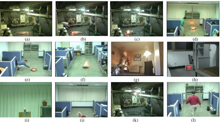
(4) The pixel in the 代表區域像素 changed region. 代表主要火焰顏色 Dominant fire colors. G. B. d5 d4. Rm. d3 d2 d1. R. Fig. 5. The distance between the sample pixel and the dominate flame colors.. 4: EXPERIMENTAL ANALYSIS. RESULTS. AND. The experimental environment is depicted as follows: − Personal Computer : CPU-Pentium III 3.0G, RAM=1GB, Hard Disk=200GB − Operation System : Window XP − Development Tool : Matlab 7.0 − Image and Video Editing Tools : Photoshop 7 and. Premiere Pro 1.5 − Camera : Single Static Camera, SONY PC-350 The experimental database consists of 16 video sequences which the frame rate is 30 frames per second, and the size is 720 by 480 pixels. To verify the early flame detection of the proposed method, the content of test firing video sequences must record the complete process of burning. However, these fire video sequences are not easily acquired. Most of the test video sequences are captured by ourselves under safety control. Only the video of burning Christmas tree is referred to [10]. The distance between the camera and the flame is at least three meters. The key-frames of the 12 video sequences for flame alarm detection are depicted as Fig. 6. Video sequences (a), (b), and (c) are made from the burning of gasoline, diesel fuel, and paper in a vessel, respectively. Video sequences (d), (e), and (f) are made from the burning of gasoline, diesel fuel, and paper in an indoor room, respectively. The content of video sequence (g) is the burning Christmas tree obtained form [10]. Video sequences (h), (i), (j), (k), and (l) are made from lighting up a candle and a lighter, turning on an electric radiator and a bulb, and a walking person with a red coat, respectively.. (a). (b). (c). (d). (e). (f). (g). (h). (i). (j) (k) Fig. 6. The key-frames of the 12 video sequences for flame alarm detection.. For the proposed method, the elementary, medium, or emergency flame alarm is issued while the pixels of changed regions conform to 3, 4, or 5 dominant flame colors of DFCLT. The dangerous flame detection results of the proposed method for the 12 video sequences as shown in Fig. 6 are depicted in Fig. 7. The comparison of the proposed method and the decision rule method [5] for flame detection is shown in. (l). Table 2. For the dangerous firing video sequences 1 to 7, the proposed method can all distinguish flame alarm to elementary, middle, or emergency level of fire except the video sequence 4. Because the burning process of gasoline in the video sequence 4 is violent, the middle fire alarm is direct issued. On the contrary, the decision rule method can not detect flame for the video sequences 1, 3, 4, and 6. The reasons are that the. - 1182 -.
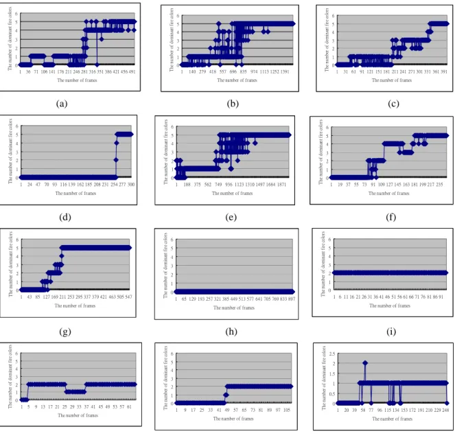
(5) 6 5 4 3 2 1 0 36 71 106 141 176 211 246 281 316 351 386 421 456 491. 6 5 4 3 2 1 0 1. 140 279 418 557 696 835 974 1113 1252 1391. 3 2 1 0 1. 24 47 70 93 116 139 162 185 208 231 254 277 300. 6 5 4 3 2 1 0 1. 188 375 562 749 936 1123 1310 1497 1684 1871. The number of frames. 4 3 2 1 0 1. 43 85 127 169 211 253 295 337 379 421 463 505 547. 5 4 3 2 1 0 1. 65 129 193 257 321 385 449 513 577 641 705 769 833 897. 3 2 1 0 1. 5. 9 13 17 21 25 29 33 37 41 45 49 53 57 61 The number of frames. 5 4 3 2 1 0 1. 19 37 55 73 91 109 127 145 163 181 199 217 235 The number of frames. 6 5 4 3 2 1 0 1 6 11 16 21 26 31 36 41 46 51 56 61 66 71 76 81 86 91 The number of frames. (i). 6 5 4 3 2 1 0 1. 9. 31 61 91 121 151 181 211 241 271 301 331 361 391. 6. (h) The number of dominant fire colors. The number of dominant fire colors. 4. 1. The number of frames. (g) 5. 0. (f). 6. The number of frames. 6. 1. (e) The number of dominant fire colors. The number of dominant fire colors. 5. 2. The number of frames. (d) 6. 3. (c) The number of dominant fire colors. 4. 4. The number of frames. The number of dominant fire colors. 5. 5. (b) The number of dominant fire colors. The number of dominant fire colors. (a) 6. 6. The number of frames. The number of frames. 17 25 33 41 49 57 65 73 81 89 97 105 The number of frames. The number of dominant fire colors. 1. the early flame detection than the decision rule method. For the non-flame video sequences 8, 9, 10, 11, and 12, the proposed method does not issued any flame alarm. On the contrary, a false flame alarm is made in the video 8 by the decision rule method.. The number of dominant fire colors. The number of dominant fire colors. The number of dominant fire colors. growing rule is failed for the rapid and violent burning, e.g., the burning of gasoline in video sequences 1 and 4, and the variable rule is lost for the slowly burning, e.g., the burning of paper in video sequences 3 and 6. Furthermore, the real early flame in the video sequences 2 and 5 is near frame 453 and 720, respectively. It is verified that the proposed method is more suitable for. 2.5 2 1.5 1 0.5 0 1. 20 39 58 77 96 115 134 153 172 191 210 229 248 The number of frames. (j) (k) (l) Fig. 7. The dangerous flame detection results of the proposed method for the 12 video sequences as shown in Fig. 6. 5: CONCLUSION In this paper, we proposed the FCM clustering algorithm to create the DFCLT for dangerous flame detection in a vessel, and three degree of flame alarms, elementary, middle, and emergency, are issued. The proposed method outperforms the decision rule method for the reducing of false flame alarms, and detecting of flame alarms, early and correctly. Here we would like to mention the following areas of investigation which may merit further study. 1) Adjust the proposed method for panned cameras or multiple cameras to extend the detection area.. 2) Combine the characteristics of color, shape, texture, and spatial relationships to improve the performance. 3) Apply the proposed method to other applications, such as to distinguish the ion of burning metal according to the burning flame color in Chemistry. ACKNOWLEDGEMENTS. This research supported by NSC 95-2221-E-014-021。. - 1183 -. is.
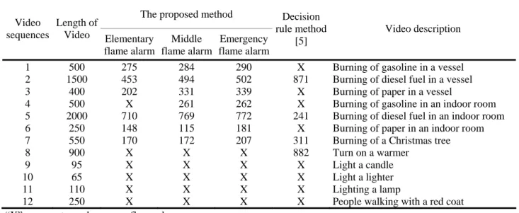
(6) Table 2. The comparison of the proposed method and the decision rule method for dangerous flame detection. The proposed method Decision Video Length of rule method sequences Video Elementary Middle Emergency [5] flame alarm flame alarm flame alarm 1 500 275 284 2 1500 453 494 3 400 202 331 4 500 X 261 5 2000 710 769 6 250 148 115 7 550 170 172 8 900 X X 9 95 X X 10 65 X X 11 110 X X 12 250 X X “X” represents no dangerous flame alarm. 290 502 339 262 772 181 207 X X X X X. X 871 X X 241 X 311 882 X X X X. Video description. Burning of gasoline in a vessel Burning of diesel fuel in a vessel Burning of paper in a vessel Burning of gasoline in an indoor room Burning of diesel fuel in an indoor room Burning of paper in an indoor room Burning of a Christmas tree Turn on a warmer Light a candle Light a lighter Lighting a lamp People walking with a red coat. J (U ,V ) = ∑∑ µ c. REFERENCES. n. i =1 k =1. [1] S. Noda, K. Ueda, ”Fire detection in tunnels using an image processing method”, IEEE Proceedings on Vehicle Navigation and Information Systems Conference, pp. 57-62, 1994. [2] S. Y. Foo, ”A machine vision approach to detect and categorize hydrocarbon fires in aircraft dry bays and engine compartments”, IEEE Trans. Industry Applications, vol. 36, pp. 549-566, March/April 2000. [3] G. Healey, D. Slater, T. Lin, B. Drda, and A. D. Goedeke, ”A system for real-time fire detection”, IEEE Proceedings on Computer Vision and Pattern Recognition(CVPR) , pp. 605-606, June 15-17, 1993. [4] H. Yamagishi and J. Yamaguchi, ”Fire flame detection algorithm using a color camera”, in Proc. Int. Symp. Micromechanics and Human Science, pp. 255-260, 1999. [5] Walter Phillips III, Mubarak Shah, and Niels da Vitoria Lobo, ”Flame recognition in video”, Pattern Recognition Letters, Vol. 23, Issue. 1-3, pp. 319-327, January 2002. [6] T. H. Chen, P. H. Wu, and Y. C. Chiou, ”An Early Fire-Detection Method Based on Image Processing ”, IEEE International Conference on Image Processing (ICIP), vol. 3, pp.1707 - 1710, Otc. 2004. [7] Y. Dedeoglu, B. U. Toreyin, U. Gudukbay, and A. E. Çetin, ”REAL-TIME FIRE AND FLAME DETECTION IN VIDEO”, IEEE International Conference on Acoustics, Speech, and Signal Processing (ICASSP), pp. 669-672, March 2005. [8] W. B. Horng, J. W. peng, and C. Y. Chen, ”A New Image-Based Real-Time Flame Detection Method Using Color Analysis”, IEEE International Conference on Networking, Sensing and Control, Tucson, Arizona, USA, pp. 100-105, March 2005. [9] A. K. Jain and R. C. Dubes, ”Algorithms for Clustering Data”, Prentice-hall, 1998. [10] U.S. Fire Administration working for a fire-Safe America , ” Holiday Fire Prevention ” , http://www.usfa.fema.gov/safety/tips/treefir.shtm。. w ik. x k − Vi. (A1). 2. where, c represents the number of clusters, n the number of data items, w the exponential weight, X={x1,x2,x3,…,xn } an n-dimensional data vector, V= {v1,v2,…,vc} a vector of dimension c, U=(μik) a c*n matrix, whereμik represent the membership value of vector xk in cluster i, and 0≦µik≦1 i=1,2,…,c; k=1,2,…,n. ∑µ c. i =1. k=1,2,…,n. =1. ik. 0 ≤ ∑µ ≤ n n. i=1,2,..,c.. ik. k =1. The minimization of the objective function with respect to membership values leads to 1. µ. ik. ⎡ ⎤ 1 ⎢ ⎥ 2 ⎥ ⎢ ⎣ x k − Vi ⎦ ⎡ ⎤ c 1 ⎢ ⎥ ∑ ⎢ j = 1 2 ⎥ ⎢ x k − Vj ⎥ ⎣ ⎦. =. (m. 1. − 1. (m. ). − 1. ). i=1,2,…,c; k=1,2,…,n. (A2) The minimization of the objective function with respect to the center of each cluster gives rise to the following equality. Vi =. APPENDIX. FUZZY C-MEANS The purpose of FCM [21] is to minimize the object function J(U,V):. - 1184 -. ∑µ x n. m. k =1. ik. ∑µ n. m. k =1. ik. ik. i=1,2,…,c.. (A2).
(7)
數據

+2
相關文件
In order to facilitate the schools using integrated or mixed mode of curriculum organization to adopt the modules of Life and Society (S1-3) for improving their
volume suppressed mass: (TeV) 2 /M P ∼ 10 −4 eV → mm range can be experimentally tested for any number of extra dimensions - Light U(1) gauge bosons: no derivative couplings. =>
incapable to extract any quantities from QCD, nor to tackle the most interesting physics, namely, the spontaneously chiral symmetry breaking and the color confinement..
• Formation of massive primordial stars as origin of objects in the early universe. • Supernova explosions might be visible to the most
Like the proximal point algorithm using D-function [5, 8], we under some mild assumptions es- tablish the global convergence of the algorithm expressed in terms of function values,
The difference resulted from the co- existence of two kinds of words in Buddhist scriptures a foreign words in which di- syllabic words are dominant, and most of them are the
(Another example of close harmony is the four-bar unaccompanied vocal introduction to “Paperback Writer”, a somewhat later Beatles song.) Overall, Lennon’s and McCartney’s
Microphone and 600 ohm line conduits shall be mechanically and electrically connected to receptacle boxes and electrically grounded to the audio system ground point.. Lines in
