IEEE TRANSACTIONS ON MICROWAVE THEORY AND TECHNIQUES, VOL. 42, NO. I, JULY 1994 1561
A Modified Finite Element Method for
‘Analysis of Finite Periodic Structures
Shyh-Jong Chung and Jiunn-Lang Chen
Abstract-A modified finite element method with new solving algorithm is proposed to analyze electromagnetic problems of finite periodic structures. Dielectric-loaded parallel-plate waveg- uides with rectangular and triangular dielectric gratings are tackled as an example of the present approach. Numerical results are checked by the self-convergence test and by comparing with those obtained by other methods. Finally, the dependence of the scattering parameters on the frequency, the period number, and the grating height is analyzed and compared.
I. INTRODUCTION
N recent years, the finite element method (FEM) has been
I
used to analyze wave guiding and scattering problems of microwave, millimeter-wave, and optical components [ 11-15]. When appropriately combined with other techniques (e.g., Green’s function technique 121, 131, eigenfunction expansion method [4], absorbing boundary condition [5]), this method can, in general, tackle arbitrary geometries with inhomoge- neous, anisotropic, and/or lossy mediums.Before applying the finite element method, one first estab- lishes a variational equation for the problem to be handled. According to the geometry of the problem, the structure is then divided into several subregions, called elements. The fields in each element are expanded by the so-called nodal field values, (which are values of the fields in some particular points (nodes) of the element and are to be determined,) and the corresponding “shape functions” (bases) [6]. After using the Rayleigh-Ritz procedure, a submatrix of the element can be obtained. Finally, by assembling the submatrices of all the elements, one gets a system matrix equation from which the nodal field values are solved.
In most cases, the system matrix is highly sparse, and thus the frontal solution technique [7] is usually used in the solving process of the equation to reduce the computation time and the core storage requirements. The technique includes two phases, i.e., assembly and elimination. Whenever a submatrix of a new element is gotten, it is assembled to the existing (working) matrix. The working matrix is then reduced by eliminating the variables that won’t appear in the rest elements. As all the elements have been called in, the resulting working matrix becomes that corresponding to the variables of the boundary nodes. By this final matrix, the scattering parameters or the eigenvalues are calculated.
Manuscript received June 1, 1993; revised October 19, 1993. This work was
supported by the National Science Council of the Republic of China under Grant NSC 82-0404-E-009-396.
The authors are with the Institute of Communication Engineering, National Chiao Tung University, 1001 Ta Hsueh Rd., Hsinchu, Taiwan, R.O.C.
IEEE Log Number 9402946.
Although the finite element method coupled with frontal so- lution technique is versatile for the analysis of electromagnetic problems, it still needs improvement to increase its efficiency, especially for the structures with high repetition, e.g., periodic structures, or with large areas of homogeneous regions. (The later can be treated as special cases of the former.) In these structures, although the field distributions are different from one period to another, the discretization of the structure in each period may be made the same. The resultant matrix obtained from the frontal solution technique for each period is thus the same. This means that one only needs to establish the matrix once but not for every period.
Periodic structures appear in many devices, such as filters, gratings, and distributed feedback lasers. For the analysis of these problems, most researchers assumed infinite periods ex- isting in the structure, and used Floquet’s theorem 181 to focus the problem into a single period. Only a few handled with the finite periodic structures [9]-[ll], among which [9] used the network representation to connect the contribution of each period and [lo] proposed a method based on the spectrum- domain analysis, combined with the sampling theorem, to treat finite periodic structures. Although available for arbitrary number of periods, these approaches could tackle only the periodic structures with step discontinuities.
In this paper, we propose a modified finite element method for the analysis of structures with high repetition. In the dis- cretization of the structure, we first divide the whole area into several blocks, called “super-elements”. Due to the repetition property of the geometry, these super-elements belong only to a few patterns. (For example, in a finite periodic structure, each period is treated as a super-element, and the whole structure contains only one (geometric) pattern). For each pattern, we divide it into many ordinary elements, and expand the fields in each element by the nodal field values and the shape functions. Through the treatment of the Rayleigh-Ritz procedure and the frontal solution technique, one obtains a submatrix corresponding to the variables of boundary nodes of the pattern. To this end, the frontal solution technique is again used to assemble and eliminate the submatrices of the super-elements. The final matrix is then obtained after this process.
The organization of this paper is as follows: Section I1
describes the theory of the method. Section 111, as an example of the theory, deals with a finite periodic planar dielectric structure with top and bottom covers. The numerical results are then presented in Section IV, followed by conclusions in Section V.
1562 IEEE TRANSACTIONS ON MICROWAVE THEORY AND TECHNIQUES. VOL. 42, NO. 8, AUGUST 1994
t P E C
P E C
Fig. 1. Dielectric scatterers located in a parallel-plate waveguide.
11. THEORY
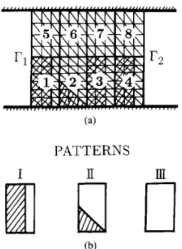
As an illustration of the theory, consider a two-dimensional structure as depicted in Fig. I, which shows four dielectric obstacles located in a parallel-plate waveguide. The spacing between the first (rectangular) and the second (triangular) dielectrics is the same as that between the third and fourth (rectangular) dielectrics. A TE mode of the parallel-plate waveguide is incident from the left-hand side (LHS), which will excite some modes reflected back to the LHS and some transmitted to the right-hand side (RHS). From a partial variational principle [ 121, one obtains a variational equation as follows:
6"I"
= 0where 0, sandwiched by boundaries I?l and r2, denotes a
finite region enclosing all the obstacles as shown in Fig. 2(a).
I
'
,
,
means the inner face (inside 0 ) of r1,2. The variational operator 6" operates only on the terms with superscript "a".To solve (1) by the finite element method, R is divided into
N small triangular elements (as shown in Fig. 2(a)), so that
the functional I" can be written as
N
I" = XI: +IF.
e = l
Here 1: represents the functional corresponding to the e- th triangular element, and If corresponding to the boundaries and
rz.
By the repetition nature of the structure, the Nsmall elements are grouped into N s ( = 8) "super-elements", as indicated in Fig. 2(a). These super-elements belong to the three patterns shown in Fig. 2(b): super-element 1, 3, 4 are of pattern I, super-element 2 is pattern I, and super-elements 5, 6, 7, 8 pattern IU. (Here super-element 6 is assumed to have the same dimensions as super-elements 5 , 7, 8.) By appropriate division, the super-elements of the same pattern may have the identical discretization. Assuming pattern i, i=I,
II,
m,
be comprosed of N , small elements, (2) is rewritten asPATTERNS
(b)
Fig. 2.
triangular elements. (b) Three structure patterns of the super-elements.
(a) Finite-element discretization including super-elements and small
where I: represents the functional of the s-th super-element,
The field in each triangular element is expanded by the field values at six nodes of the element, three on the vertices and three on the mid-pionts of the edges. By using the Rayleigh-Ritz procedure and the frontal solution technique, the variational operation on 1: would result in a submatrix
A , associated only with the field values of the boundary nodes of the s-th super-element. Note that, owing to the same dimensions and discretization, the super-elements of a pattern would have the same submatrix. Thus, one only needs to calculate three submatrices for the present example. (Each submatrix of a pattern is obtained by assembling and eliminating N , sub-submatrices of the triangular elements.)
By using >e frontal solution technique a@n, the N ,
submatrices
(zs,
s=l,...,
N s ) and the submatrix2~
(associated with IF) are then gathered in turn to get the final matrix equation,-
-
with
3
being the nodal field values of boundaries rl and I'2,and S the sources terms associated with the incident field. The scattering parameters are determined from the solution of ( 5 ) . Before the end of this section, it is noticed that the eight super-elements shown in Fig. 2(a) can be considered as four new super-elements, that is, super-elements (1,5). (2,6), (3,7),
and (4, 8). These new super-elements belong to two pattems, thus only two submatrices are needed to be obtained.
111. APPLICATION TO FINITE PERODIC STRUCTURES Fig. 3 shows a periodic dielectric waveguide with top
and bottom PEC covers, where a N,-period structure is connected to two semi-infinite dielectric-loaded parallel-plate waveguides. The materials in each period may be arbitrary and may contain PEC's. Let the incident field be the TE dominant
CHUNG AND CHEN: A MODIFIED FINITE ELEMENT METHOD FOR ANALYSIS OF FINITE PERIODIC STRUCTURES 1563
PEC
Fig. 3.
number of the periods in the structure.
Periodic dielectric waveguide with top and bottom covers. AVc is the
mode (slab-guide mode) of the dielectric-loaded parallel-plate waveguide.
The fields exterior to the boundary r1 are expanded by the orthonormal modes of the dielectric-loaded parallel-plate waveguide, Le., A I E,(r;) =
+
R~+) (6) i=l and AIH,(r;)
= hl(z)+
nihi(z),
(7) i = lwhere e;(z) is the modal function of the i-th mode, hi(.) =
- 3 ,
-e;(x), with
pi
being the propagation constant of the mode. Ri is the reflection coefficient to be determined. By the continuities of the tangential fields and the orthonormality of the modes, one getsWPO
R~
= -hli+
i q , ( r ; ) / L i ( x ) d z ,
(8)and thus
&(q)
=&(q)
With a similar treatment to the boundary
r2,
one obtainsand
where
'rl
is the (unknown) coefficient of the ith mode trans- mitted to the RHS waveguide.By casting (9) and ( 1 1 ) into ( l ) , a variational equation containing only the electric field inside R is obtained, which is then solved by the method mentioned in the previous section. In the discretization of the structure, each period is treated as a super-element. Besides, two aditional uniform sections immediately adjacent to the periodic stucture are included in
(1 and are considered as two super-elements (see Fig. 3). The inclusion of these two sections can reduce the number (M) of
I h r i c STRUCTURE A pi2 'Pi2 STRUCTURE B t - P S STRUCTURE C
Flg. 4. Periodic structures to be analyzed. For Ftructures A and C, f, = 5.
t = 1.8mm, h l = 0. For structure B, 6 , = 11.8, t = 0.7mm, hi = h 2 = 1 mm.
the waveguide modes required to expand the fields on
rl and
rz,
due to the decays of the higher-order evanescent modes. Thus, there are totally N ,+
2 super-elements in R, which belong to two patterns, Le., the pattern of the period and that of the uniform section.The essential boundary condition on the PEC covers (Le., tangential electric fields to be zero) is enforced in the process of obtaining the submatrices of the patterns. This makes the submatrix associated only with the nodal field values of the two side boundaries of the pattern. Thus, whenever a new super-element is called in, after assembly and elimination, the resulting working matrix always contains the variables of
rl
and those of the RHS boundary of that super-element, assuming that the super-elements are called in one by one from left to right. (The variables of rl can not be eliminated since they will appear in the last element, Le., the last term of (3)). In other words, the size of the working matrix is kept constant, not getting larger with the increase of the number of treated super-elements.After the last element having been called in, the working matrix becomes the final (system) matrix and the source terms are introduced. The solutions of the resulting matrix equation are the electric fields on
rl
andrz,
Le.,Ey(I';)
andEY(r;).
The reflection coefficients Ri's and transmission coefficients T,'s are then calculated from (8) and (10).
IV. NUMERICAL RESULTS
We present in this section some numerical results for the finite periodic structures shown in Fig. 4. Some of the geometric parameters are indicated in the figure, others defined in Fig. 3. The number (M) of the modes, including propagation and evanescent modes, of the dielectric-loaded parallel-plate
1564 IEEE TRANSACTIONS ON MICROWAVE THEORY AND TECHNIQUES, VOL. 42, NO. 8. AUGUST 1994
Nx Nz
IRlLR ITlLTP,,,
Y
-
PRESENT AUALYSIS-____
RESULTS F R O M [11] lo^"""".'..' '....'.,..I. . . . I 35 40 45 50 55 60 65 F R E Q U E N C t ( G H z )Fig. 5. Variation of the reflection coefficient as a function of the frequency for the structure B shown in Fig. 4. .V, = 2 0 , p = 1.36mm, t , = 0.03".
waveguide is set to be 10. Although not shown here, further increase of this number does not influence the calculated results.
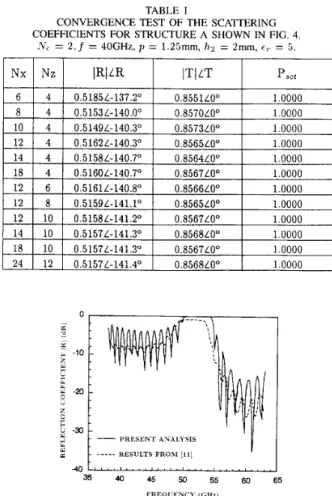
Table I shows a convergence test of the slab-guide reflection (R) and transmission (T) coefficients for the structure A with 2 periods ( N e = 2). Nx and Nz represent the division mesh numbers in the x and z directions, respectively, inside a period. It is seen that good convergence is obtained both for the magnitudes and phases of the coefficients. The power conservation law, i.e., the absolute squares of the scattering coefficients of all the propagation modes are added to be unity,
is always obeyed for this and the following calculations. As a further test of the present method, Fig. 5 shows the magnitude of the reflection coefficient R (of the slab-guide mode) as a function of the frequency for the structure B with Ne = 20. The results of the dash line are from [ l l ] ,
in which the obstacles (PEC's) embedded in the uniform slab are replaced by highly dopped plasmas (a = 2.44 x 10'S/rn). The infinite conductivity of the obstacles makes the curve of the present analysis (solid line) having higher values in the flat band and larger oscillations than that of [ I 11. Except for these differences, the two curves behave quite similarly in the whole frequency band.
22 24 26 28 30 32 34 6
F R E Q U E N C Y ( G H z )
Fig. 6 .
for the structure A shown in Fig. 4.
Variation of the reflection coefficient as a function of the frequency = 2O.p = 3.6". H2 = 2 t . 1 0.8 a 0.6 w
:
0.4 0.2 - h = 0 . 2 5 t 0 5 10 15 20 25 30 PERIOD NUMBER (Nc)Fig. 7. Variations of the reflection (R-) and transmission CPt) powers as
a function of the period number (Xc) for the structure A shown in Fig. 4.
f = 29.2GHz, p = 3.6mm, h 2 = 2 t .
Fig. 6 illustrates the frequency response of the reflection coefficient for the structure A ( N e = 20) with h = 0.25t (solid line) and h, = 0.5t (dash line). It is seen that the increase of the height of the ridges has a little influence on the upper end of the reflection band, but has large on the lower end. The expense of this increased bandwidth is the raise of the side lobes in the lower frequency.
There are three dielectric thicknesses associated with the stuctures of Fig. 6, i.e.,
t ,
1 . 2 3 (for h = 0.25t), and 1.5t (for h = 0.5t). For the given period length (p = 3.67nm) and dielectric constant (er = 5 . ) , to satisfy the Bragg reflectioncondition based on the first order perturbation theory [13], i.e., , O ( f ) p = 7r. the required frequencies for the slab waveguides
with the three dielectric thicknesses are calculated to be 30.75, 27.85, and 25.90 GHz, respectively. It is interesting to note that the mean value of the first two frequencies is 29.3 GHz, which is approximately equal to the maximum-reflection frequency (29.2 GHz) for the solid-line curve (which is the result for the periodic structure formed by two equally spaced dielectrics with thickness t and 1.2%). Similarly, the mean value of the first and last frequencies, i.e., those for dielectric thicknesses
t and 1 3 , is 28.33 GHz, which, again, is approximately equal to the maximum-reflection frequency (28.2 GHz) for the dash-line curve.
Fig. 7 shows the variations of the reflection (P,) and transmission (P,) powers (of the slab-guide mode) with the
CHUNG AND CHEN: A MODIFIED FINITE ELEMENT METHOD FOR ANALYSIS OF FINITE PERIODIC STRUCTURES
0 5 10 15 20 25 30 PERIOD XCMBER ( N r )
Fig. 8. Variations of the reflection (solid lines) and transmission (dash lines) powers as a function of the period number (LVc.) for the structure A shown in
Fig. 4. The arrows indicate the increase of h . 2 . f = 29.2GHz, 11 = 3.Gmm. It = 0.25t.
increase of the period number (N,.) for the structure A with
h = 0.25t and h = 0.5t. Since the frequency is chosen to be 29.2 GHz, which is simultaneously inside the two reflection bands of Fig. 6, the reflection power P, (transmission power
Pt) increases (decreases) monotonically to unity (zero) both for h, = 0.25t and h = 0 . 5 t . For a given number of periods, the reflection power of 11 = 0.5t (dash line) is larger than that
of \i = 0.25t (solid line), due to the stronger reflection at each step-discontinuity. In other words, to get a given reflection power, the total length of the structure with h = 0.5t will be shorter than that of the structure with h = 0.25t, since less periods are needed for the former structure.
Fig. 8 presents the reflection (solid lines) and transmission (dash lines) powers as a function of the period number for the structure A with several heights h2 (defined in Fig. 3) of the upper cover. The curves for h,2 = 4t, 6t, 10t
(t
= 1.87rl7rL)are almost the same since their propagation constants of the slab-guide mode are nearly identical
( p
0.796 rcdlmni). As the height of the upper cover is reduced to h2 = 2t, the propagation constant is varied a little (fi
= 0.788 r n d . / m r r r ) ,but the curve of P, (Pt) still increases (decreases) monotoni- cally with the increase of the period number. This phenomenon is changed when the upper cover is further pressed down to
h2 = t . At this height the propagation constant is changed to 0.730 rad./mrn due to the strong influence of the cover on the field of the slab-guide mode. This seriously destroys the Bragg reflection condition for the given length of the periods
(JJ = 3 . 6 7 r i m ) . For this reason, the curves of P, and Pt for
hz = t oscillate and do not change monotonically with the increase of N,.
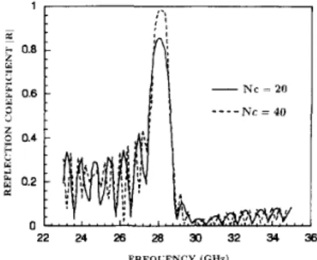
The frequency response of the reflection coefficient of a triangular grating shown as the structure C of Fig. 4 is illustrated in Fig. 9. The solid line respresents the result for 20 periods, and the dash line for 40 periods. It is noted that the increase of the period number can raise the main- lobe level, while keep the main-lobe bandwidth and side-lobe levels unchanged. Also note that from our calculations, the magnitudes of the reflection coefficients for a TE dominant mode incident from RHS are the same as those for that coming from LHS, as is the consequence of the power conservation law [8].
5
0.4 c Y 2 0.2 1 n 1565 22 24 26 28 30 32 34 36 FREQCENCY (GHZ) Fig. 9.for the structure C shown in Fig. 4. 11 = S.Gmm, h = 0.2.5t. h 2 = 2 t .
Variation of the reflection coefficient as a function of the frequency
V. CONCLUSIONS
We have improved the algorithm of the finite element method for solving scattering and guiding problems of highly repetitive structures. The whole structure is divided into sev- eral super-elements which can be grouped into a few pat- terns due to the repetition property of the structure. Each super-element is discretized to many small elements and the Rayleigh-Ritz procedure and the frontal solution technique are used to obtain a submatrix for the super-element. Only a few submatrices are needed to calculate since the super-elements belonging to a pattern would lead to the same matrix. By assembling the submatrices of all the super-elements, a final system matrix equation is obtained and then solved.
The validity of the proposed method has been checked by the self-convergence test and by comparing the numerical results with those obtained by another method. Also the power conservation law has been fulfilled for all the calculations. Numerical results, including the frequency response and the dependence on the period number of the scattering parameters, for finite periodic structures in dielectric-loaded parallel-plate waveguides have been presented. It has been found that, to predict the maximum-reflection frequency of a rectangular grating, one may approximately take the mean value of the Bragg-reflection frequencies (for a given period length) of the two slab waveguides with thicknesses t and t
+
h (see the structure A of Fig. 4). The increase of the period number has little influence on the main-lobe bandwith and the side- lobe levels of the frequency spectrum, but it does increase the reflection power in the main lobe.The proposed method can be applied to any variational equation to be solved by the finite element method, although a partial variational equation has been used in this paper. Besides, the efficiency of the present method is more obvi- ous when more complicated structures, such as semiperiodic structures arbitrarily formed by two or more structure patterns, are tackled.
REFERENCES
[ 11 G. 1. Costache, “Finite element method applied to skin-effect problems in strip transmission lines,’’ IEEE Truns. Microwuve T h e o y Tech., vol. 35, pp. 1009-1013, Nov. 1987.
I566 IEEE TRANSACTIONS ON MICROWAVE THEORY AND TECHNIQUES. VOL. 42. NO. 8, AUGUST 1994
[2] J.-M. Jin and J . L. Volakis, “A finite element-boundary integralformula- tion for scattering by three-dimensional cavity-backed aperatures,” IEEE Trans. Antennas Propagat., vol. 39, pp. 97.104, Jan. 1991. [3] S.-J. Chung and C. H. Chen, “A partial variational approach for arbitrary
discontinuities in planar dielectric waveguides,” IEEE Trans. Microwave Theory Tech., vol. 37, pp. 208-214, Jan. 1989.
[4] R.-B. Wu and C. H. Chen, “Variational reaction formulation of scattering
problem for ansiotropic dielectric cyinders,” IEEE Trans. Antennas Propagat., vol. 34, pp. 640-645, May 1986.
[ 5 ] J. P. Webb, “Absorbing boundary conditions for the finite-element
analysis of planar devices,” ZEEE Trans. Microwave Theory Tech., vol. 38, pp. 1328-1332, Sept. 1990.
161 0. C. Zienkiewicz, The Finite Element Method. New York: McCraw- Hill, 1977.
[7] P. Hood, “Frontal solution program for unsymmetric matrices,” Int. J.
Num. Meth. Eng., vol.10, pp. 379-399, 1976.
[8] R. E. Collin, Field Theory of Guided Waves. New York: McCraw-Hill,
1960.
[9] T. E. Rozzi and G. H. In’tveld, “Field and network analysjs of interacting step discontinuities in plannar dielectric waveguides,” IEEE Trans. Microwave Theoty Tech., vol. 27, pp. 303-309, Apr. 1979.
[IO] K. Uchida, “Numerical analysis of surface-wave scattering by finite periodic notches in a ground plane,’’ IEEE Trans. Microwave Theory Tech., vol. 35, pp. 481-486, May 1987.
[ I 11 M. Matsumoto, M. Tsutsumi, and N. Kumagai, “Bragg reflection chac- teristics of millimeter waves in a periodically plasma-induced semicon- ductor waveguide,” IEEE Trans. Microwave Theor3; Tech., vol. 34, pp.
406-41 1, Apr. 1986.
[I21 S.-J. Chung and C. H. Chen, “Partial variational principle for elec- tromagnetic field problems: Theory and applications,” fEEE Trans, Microwave Theory Tech., vol. 36, pp. 473-419, Mar. 1988.
[ 131 D. Marcuse, Light Transmission Optics. New York: Van Nostrand,
1982.
ShyhJong Chung was born January 18, 1962 in
Taipei, Taiwan. He received the B.S.E.E. and Ph.D. degrees from National Taiwan University, Taipei, Taiwan, in 1984 and 1988, respectively.
Since 1988, he has been with the Department of Communication Engineering, National Chiao Tung University, Hsinchu, Taiwan, where he is currently an Associate Professor. His research interests in- clude waveguide discontinuities, wave propagation, and numerical techniques in electromagnetics.
Jiunn-Lang Chen was born December 26, 1967, in Taiwan. He received the M.S. degree from the National Chiao Tung University, Hsinchu, Taiwan in 1993.
He has been engaged in the research on theo- retical and numerical analysis of electromagnetic radiation, scattering problems.