Persistent currents in toroidal carbon nanotubes
M. F. LinDepartment of Physics, National Cheng Kung University, Tainan 70101, Taiwan, Republic of China D. S. Chuu
Electrophysics Department, National Chiao Tung University, Hsinchu 30050, Taiwan, Republic of China ~Received 27 May 1997!
The geometric structure of the toroidal carbon nanotubes~TCN’s! determines the electronic structure and thus the characteristics of the persistent current. Such current is caused by the magnetic fluxf through TCN’s. The semiconducting TCN’s exhibit diamagnetism at smallf, which is in great contrast with paramagnetism of the metallic TCN’s. The induced magnetic moment is proportional to the toroid radius, but independent of the toroid width. The magnetic response is weak, while it is much stronger than that of a mesoscopic semicon-ductor or metal ring. The persistent current is a linearly periodical function off, with a period f0(hc/e). Such
an oscillation is the manifestation of the Aharonov-Bohm~AB! effect. Temperature (T) does not destroy the periodical AB oscillation, although it would significantly reduce the persistent currents. The Zeeman splitting may lead to the destruction of the periodicity at very largef. A larger TCN at lower T and f is relatively suitable for verifying the AB effect.@S0163-1829~98!01412-X#
I. INTRODUCTION
Carbon nanotubes have attracted a lot of attention since their discovery in 1991 by Iijima.1 Each straight carbon nanotube ~SCN! could be regarded as a rolled-up graphite sheet in cylindrical form. Its radius (r) is only between 10 and 150 Å, while its length is more than 1 mm. Carbon nanotubes could bend within the crystalline rope;2moreover, the two ends are found to be able to be knit together seamlessly.3 Carbon atoms could form a toroidal carbon nanotube@~TCN! or a carbon toroid#, with an average radius
R;1500– 2500 Å. The toroid radius is much larger than the
height or the width ~;10 Å!. A very thin TCN is basically similar to a mesoscopic metal4–6 or semiconductor7 ring. TCN’s, as with mesoscopic rings, would be the ideal system for verifying certain quantum effects, e.g., the persistent cur-rents~I’s!.4–7Such currents are purely due to magnetic flux ~f! through TCN’s. The electronic structure of the TCN’s and the characteristics of the persistent currents are studied in this work. The dependence of the persistent current on the magnetic flux, the electronic structure, the toroid radius (R), the temperature (T), and the Zeeman splitting is investi-gated. A comparison between TCN’s and SCN’s Refs. 8–10 will be made.
The toroidal forms of graphitic carbons could be con-structed from nanotubes by~1! connecting small sliced parts of the nanotubes,11 ~2! connecting two sections of identical turnover bilayer nanotube ends at the equator of the resulting toroid,12and~3! bending a long nanotube and connecting its ends together ~this work!. Dunlap first proposed the carbon toroids C576 and C540 by connecting the sliced parts of nanotubes.11 Later the second kind of carbon toroids were proposed by Itoh et al.12 These two kinds of carbon toroids have certain pentagons and heptagons instead of hexagons, while the third kind of carbon toroid is purely made from the distorted hexagonal lattices. The former have the ratio R/r ,10, which is much smaller than that ~.100! of the latter.
Hence the geometric structures of the first and the second kinds of carbon toroids are quite different than those studied in this work.
The tight-binding model13 has been used to study thep -electronic structure of a SCN.14It is similar to that employed for a graphite sheet, but with the periodical boundary condi-tion along the transverse direccondi-tion. The electronic states of a TCN are further obtained, when the periodical boundary con-dition along the axial direction is also applied. A TCN owns many discrete states, mainly owing to the transverse and lon-gitudinal boundary conditions. It may be a metal or a semi-conductor, which is closely related to the geometric struc-ture. A semiconducting TCN has an energy gap (Eg)
between the highest occupied states ~HOS! and the lowest unoccupied states~LUS!. But for a metallic TCN, both HOS and LUS are just located at the Fermi level (EF50).15,16 The characteristics of the electronic structures will be di-rectly reflected in the persistent current. A TCN would dras-tically change from a metal ~semiconductor! to a semicon-ductor ~metal! during the variation of f. As a result of the large R, the Zeeman effect is generally negligible except at very largef. Thef-dependent electronic states are periodi-cal in f, with a periodf05hc/e, as are the persistent cur-rents. This is the so-called Aharonov-Bohm ~AB! effect. In general, such an effect is present in toroidal3,17 and cylindrical1 systems.
Haddon17had studied the magnetic properties of the C576 toroid.11It is predicted to exhibit diamagnetism. The magne-tism of the thin TCN’s will be investigated. There are certain theoretical predictions concerning the magnetic response of SCN’s.8–10The induced magnetic moment is independent of radius. Metallic and semiconducting SCN’s atf50, respec-tively, exhibit the paramagnetic and diamagnetic behavior at smallf. The magnetic response is predicted to be observable at T,100 K. Moreover, the Zeeman splitting could cause the special cusp structures and destroy the periodicity of the 57
AB oscillation.10We will study whether TCN’s exhibit simi-lar properties.
Three successful experimental investigations demonstrate that persistent currents exist in mesoscopic metal5–6 and semiconductor7rings. The magnetic moment induced by the persistent current is;10220– 10222Å m2, and its magnitude rapidly decreases in the increasing of T. The magnetic mo-ment in a mesoscopic ring is found to be much smaller than that in a thin TCN. Hence the persistent currents in TCN’s are observable in the low-temperature magnetic measure-ments.
This paper is organized as follows. In Sec. II, the p -electronic structure of a thin TCN threaded by a uniform perpendicular magnetic field (B) is calculated from the tight-binding model. The persistent currents are evaluated in Sec. III. The main features are discussed, and certain effects are investigated. Concluding remarks are made in Sec. IV.
II. ELECTRONIC STATES IN A B FIELD
We first see the geometric structure of a SCN. It is formed by rolling a graphite sheet from the origin to the vector Rx
5ma11na2, where a1 and a2 are the primitive lattice vec-tors of the graphite sheet~Fig. 1!. A SCN is equivalent to a graphite sheet which satisfies the periodical boundary condi-tion along the transverse direccondi-tion. The parameters (m,n) are used to characterize a SCN. There are two kinds of achiral SCN’s. One is the (m,m) armchair nanotube,18and the other is the (m,0) zigzag nanotube. They, respectively, have zig-zag and armchair structures along the longitudinal direction ~parallel to Ry5pa11qa2!. The armchair nanotubes are
found to be the principal constituents of the crystalline rope.2 Furthermore, they might be the precursors of the TCN’s.3
A carbon nanotube could bend so that the two ends are able to knit together. A TCN corresponds to a finite graphite sheet which is rolled from the origin to the vectors Rxand Ry
simultaneously. That is to say, a TCN satisfies the periodical boundary conditions along the transverse and longitudinal directions. The parameters (m,n, p,q), therefore, uniquely
define a TCN.19Here we mainly focus on the TCN’s, which have armchair structure along the transverse direction and zigzag structure along the longitudinal direction, and vice versa. They are called armchair (m,m,- p, p) and zigzag (m,0,- p,2p) TCN’s, respectively. Other TCN’s derived from the chiral nanotubes are expected to exhibit similar elec-tronic properties.
Thep-electronic structure of a TCN, as done in a graphite sheet,13 is calculated by the tight-binding model. A TCN here is in the presence of a uniform perpendicular B field. The gauge A5B3R/2 ~parallel to Ry! is chosen such that the wave vector k52i¹1(e/ch)A. R is the vector from the center to the surface of the toroid. The TCN is very thin; hence, the vector potential at the toroid surface is approxi-mated as a constantf/2pR. For an armchair~zigzag! TCN,
wave vectors obtained from the transverse and the longitudi-nal periodical boundary conditions are kx52pJ/3bm and ky52p(L1f/f0)/
A
3b p @kx52pJ/A
3bm and ky52p(L1f/f0)/3b p#. b51.42 Å is the C-C bond length. J 51,2, . . . ,m and L51,2, . . . ,p are the angular momenta, and they could serve as the state index. The electronic state energies of the armchair TCN are given by
E~J,L,f!armchair56g0
H
164cosS
pJ mD
cosS
p~L1f/f0! pD
14 cos2S
p~L1f/f0! pDJ
1/2 , ~1a!and those of the zigzag TCN are given by
E~J,L,f!zigzag56g0
H
164 cosS
pJ mD
cosS
p~L1f/f0! pD
14 cos2S
pJ mDJ
1/2 . ~1b!The quantityg053.033 eV is the resonance integral for the nearest-neighbor interaction.14The states, with energies less ~larger! than EF50, are occupied ~unoccupied! states, if the
Zeeman splitting is absent. The2~1! sign appearing outside the square-root sign corresponds to the occupied ~unoccu-pied! states. On the other hand, the plus and minus signs inside the square-root sign are the unfolded and folded states, respectively.14That the6 signs are substituted by 1 and L 51,2, . . . ,2p ~or J51,2, . . . ,2m! is another equivalent choice. The J states, which are closest to the Fermi level
EF50, would dominate the low-frequency physical
proper-ties. For example, for an armchair TCN, the energy gap and the persistent current are principally determined by the J 5m states.
The electronic state energy should include the spB in-teraction, E(s,f)5gsf/m*R2f0, i.e., E(J,L,s,f) 5E(J,L,f)1E(s,f). The g factor is taken to be the same as that~.2! of the pure graphite or GIC’s.20 s561/2 is the electron spin, and m* is the bare electron mass. In general, the Zeeman spitting could be neglected except at very large FIG. 1. A toroidal carbon nanotube could be regarded as a finite
graphite sheet rolled from the origin to the vectors Rx5ma11na2
and Ry5pa11qa2simultaneously. a1and a2are the primitive
vec-tors of the graphite sheet.
f, since it is inversely proportional to R2. For example,
E(s,f);2meV for the ~10,10,25001,5001! TCN at f 5f0.
The electronic structures atf50 are first discussed. There are three types of electronic structures, which rely on the geometric structures. A type I TCN, which both m and p are the multiple of 3 ~3i; i is an integer!, is a metal.15–16The HOS and LUS meet with each other at EF50, e.g., the ~J
510, L53334! states of the ~10,10,25001,5001! TCN ~the solid curve in Fig. 2!. Moreover, density of states ~DOS! is divergent in d-function form there. For a type II TCN, m is equal to 3i, but the opposite is true for p. It is a narrow-gap semiconductor with Eg;1 meV, e.g., the ~10,10,
25002,5002! TCN ~the dashed curve in Fig. 2!. A type III TCN defined by mÞ3i has a large energy gap, e.g., Eg
;1.5 eV for the ~11,0,25001,5001! TCN. Such a type of TCN is very insensitive to magnetic flux, so that the persis-tent currents are almost vanishing. Type I and II TCN’s are the main object of study.
The low energy electronic structure of a (m,n, p,q) TCN could be understood from that of a (m,n) SCN. A TCN samples the p-electron states of a SCN, which satisfies the longitudinal boundary condition. When a SCN is metallic,14–16the edge state of the linear subbands is located at the Fermi level. If a TCN could~could not! sample such a state, it is a metal~a narrow-gap semiconductor!. But when a SCN is semiconducting, a TCN must be a wide-gap semi-conductor. Metallic or semiconducting TCN’s are mainly de-termined the geometric structures.
The electronic states vary with magnetic flux. The f -dependent states would exhibit the periodical oscillation, with a periodf0, in the absence of the spin-B interaction. A type I TCN would change from a metal into a semiconductor asfincreases from zero, e.g., the~10,10,25001,5001! TCN. Thef-dependent energy gap calculated from Eq.~1a! or ~1b! is Eg~f!5
H
3bg0 R f f0 if 0<f<f0/2, 3bg0 R f02f f0 if f0/2<f<f0, ~2!Egis inversely proportional to the toroid radius; furthermore, it is symmetric about f5f0/2. A type II TCN exhibits a similar oscillation, e.g., the ~10,10,25002,5002! TCN. Its energy gap is given by
Eg~f!5
H
3bg0 RU
1 32 f f0U
if 0<f<f0/2, 3bg0 RU
2 32 f f0U
if f0/2<f<f0. ~3!But on the other hand, there are two main differences be-tween type I and II TCN’s. One is that a type I TCN is a metal atfa5if0, but a type II TCN atfa5(i613)f0. The metal-semiconductor transition happens at fa. The
persis-tent current would exhibit a special jump structure there~Fig. 3!. As a result of this difference, type I and type II TCN’s might exhibit very different persistent currents, e.g., opposite magnetism at smallf. Another is that the maximum of Egis,
respectively, located atf5f0/2 andf50 for type I and II TCN’s.
III. PERSISTENT CURRENTS
The electronic state energies in Eqs. ~1a! and ~1b! are used to study the characteristics of persistent currents. They vary with the magnetic flux through a TCN. The persistent current is the variation of free energy with the magnetic flux. The canonical ensemble ~here, the same with the grand ca-FIG. 2. The magnetic-flux-dependent energy gaps in the absence
of the Zeeman splitting. The solid and dashed curves, respectively, are those of the ~10,10,25001,5001! ~type I! and ~10,10, 25002,5002! ~type II! TCN’s.
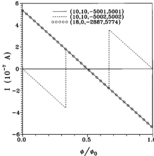
FIG. 3. The persistent currents in the absence of the Zeeman splitting are shown at T50. The solid and dashed curves are those of the ~10,10,25001,5001! and ~10,10,25002,5002! TCN’s sepa-rately. That of the ~18,0,22887,5774! TCN ~the open circles! is also shown for the comparison.
nonical ensemble! is taken in evaluating the free energy. The distribution probability of each electronic state is described by the Fermi-Dirac function
f@E~J,L,s,f!#5 1
exp$b@E~J,L,s,f!2m~T,f!#%11, ~4! whereb5(kBT)21. The chemical potentialm(T,f) is equal
to zero at T50. It remains so for any T andf. The symmet-ric structure of occupied and unoccupied states could explain whym(T,f)50. The chemical potential is independent of T andf; therefore, a TCN only exchanges energy with a res-ervoir, i.e., the particle number is fixed during the variation of f. The free energy at T is given by
F~f,T!5
(
s,J,L
21
b ln$11exp@2bE~J,L,s,f!#%. ~5!
The persistent current at T is calculated from the defini-tion I~f,T!52c ]F~f,T! ]f 52c
(
s,J,L f@E~J,L,s,f!# ]E~J,L,f! ]f , ~6a! where ]E~J,L,f!armchair ]f 572pg0sin@p~L1f/f0!/p#$6cos~pJ/m!12 cos@p~L1f/f0!/p#%
pf0
A
164 cos~pJ/m!cos@p~L1f/f0!/p#14 cos2@p~L1f/f0!/p#, ~6b!
and
]E~J,L,f!zigzag
]f 5
72pg0sin@p~L1f/f0!/p#6cos~pJ/m!]
pf0
A
164 cos~pJ/m!cos@p~L1f/f0!/p#14 cos2~pJ/m!. ~6c!
The persistent current in Eq.~6a! comes from the electronic orbital motion. The current cgs/m*R2f0 due to the spin magnetic moment is not included in Eq. ~6a!, since it is negligible. The effect of the Zeeman splitting, which is ob-vious only at largef ~Fig. 6!, is reflected in the Fermi dis-tribution. The spin-B interaction will be neglected in the fol-lowing calculations except in a special case. The expression of I(f,T) is complicated as seen from Eq.~6b! or ~6c!. The term]E(J,L,f)/]f consists of both the angular momenta J and L. Consequently, the simply linear relation, as found in a mesoscopic ring,4 between current carried by each state and angular momentum (L) is absent.
The f-dependent persistent current at T50 is first stud-ied. It is caused by the electronic states with E(J,L,f) <EF. The armchair TCN’s are taken as the model systems
to see the basic features. I(f,T50) in the ~10,10, 25001,5001! ~type I! TCN is shown in Fig. 3 by the solid curve. The persistent current is periodic with periodf0, and it is antisymmetric about f0/2. That is to say, I(f,T50) 5I(f1f0,T50)52I(f02f,T50). Both periodicity and antisymmetry are easily identified from Eq.~6b!.
The magnitude of I (;1027A) is small, i.e., the mag-netic response of a TCN is weak. By the detailed analysis, the main contributions to the persistent current are found to come from the states (J5m,L,p/3) and (J5m,L>2p/3) ~details in the Appendix!. Moreover, the currents carried by the two states L and p2L would significantly cancel each other@the first terms in Eqs. ~A4! and ~A5!#. Such cancella-tions lead to the small net current, as seen in Fig. 3. The f dependence of the persistent current, which is demonstrated to be linear @the second terms in Eqs. ~A4! and ~A5!#, is described by
I~f!5I0
S
df5fa2 2ff0
D
for 0<f,f0, ~7!
where I054
A
3pg0/ pf0 is the amplitude of the AB oscil-lation, e.g., I0;5.3831027A for the ~10,10,25001,5001! TCN. There is a special jump structure at fa, where the metal-semiconductor transition occurs. Also notice that Eq. ~7! keeps a similar form for the type II TCN. On the other hand, the contributions due to the states (J5m,p/3<L ,2p/3) and (JÞm,L) are almost vanishing. The currents, which are carried by the unfolded and folded states of (J 5m,p/3<L,2p/3), have the same magnitude but the op-posite direction. The net current due to them thus vanishes. Concerning the JÞm states, they are far from the Fermi level, so that their energies are insensitive to the variation off. Furthermore, the cancellations between the L and p2L states remain significant at anyf. The net current carried by the JÞm states is negligible, which illustrates that the per-sistent current depends on the states relatively close to the Fermi level.4
The persistent current in the type II TCN exhibits similar characteristics; the periodicity, the antisymmetry, the weak response, the linear f dependence, and the special jump structures, e.g., I(f) of the ~10,10,25002,5002! TCN ~the dashed curve in Fig. 3!. However, there are two important differences between type I and II TCN’s. First, the direction of current might be opposite. At smallf~.0!, the current of the type I TCN is positive, while that of the type II TCN is negative. That is to say, the former and the latter is paramag-netic and diamagparamag-netic, respectively. In general, the net cur-rent due to the (J5m,L) and (J5m,p2L) states is negative
at anyf @the second terms in Eqs. ~A4! and ~A5!#. But for the~J5m, L52p/3! state of the type I TCN, it could make a large and positive contribution (I0) to the net current ~Ap-pendix!. The main reason is that the current carried by the ~J5m, L5p/3! state vanishes as f increases from zero. Consequently, the paramagnetism of the type I TCN is purely caused by the ~J5m, L52p/3! state closest to the Fermi level. In addition, the opposite case would happen at
f,0. Second, the special jump structures occur at different
fa’s, and the height of the jumps is different. They are,
respectively, situated at if0 and (i61
3)f0 for type I and II TCN’s @Eq. ~7!#. These jumps are related to the metal-semiconductor transitions or vice versa. Their cause is simi-lar to that of the paramagnetism of the type I TCN. Whenf increases from the left-hand neighborhood to the right-hand neighborhood of fa, the two states, La5p/32fa/f0 and
Lb52p/32fa/f0, would induce a jump of 2I0 (I0) in the type I TCN ~the type II TCN separately!. For example, for the ~10,10,25002,5002! TCN, the jumps of I0 atf0/3 and 2f0/3 result from the L51667 and L53334 states, respec-tively.
The above-mentioned characteristics of the persistent cur-rents are obtained for the armchair TCN’s. Similar results could also be found in the zigzag TCN’s. For example, the zigzag TCN defined by~18,0,22887,5774! ~the open circles in Fig. 3! and the armchair TCN defined by ~10,10, 25001,5001! have the same persistent current. That they both belong to the type I TCN, and they have the same radius ~see below! could explain this result. In short, the geometric structure affects the electronic structure and thus the persis-tent currents.
We further see the effects due to the geometric structure ~such as radius and width!, the temperature, and the Zeeman splitting. The persistent currents are shown in Fig. 4 for vari-ous TCN’s. They are inversely proportional to the toroid radius, but independent of the toroid width. These results could be understood from Eq.~7!, in which I(f) depends on
p21, but not m21. The induced magnetic momentpR2I(f) is further identified to be proportional to the toroid radius. The larger the TCN is, the stronger the magnetic response. A larger TCN is suggested to be more suitable in the experi-mental verification of the AB effect. The magnitude of the magnetic moment is ;5310220A m2 for a TCN with R ;2000 Å. It is much larger than that (,10220A m2) in a mesoscopic ring.4–7 Hence the characteristics of the persis-tent currents in TCN’s could be verified from the magnetic measurements.
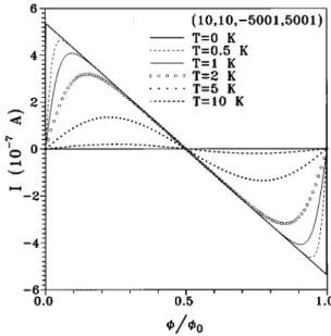
When temperature increases from zero, electrons would occupy the states above the Fermi level @E(J,L,f).0#. Such states produce the persistent current, which the direc-tion of current is opposite to that of the states below the Fermi level @Eq. ~6b!#. The cancellations between the states below and above the Fermi level obviously increase with T. Therefore, the oscillational amplitude of the f-dependent persistent current declines rapidly in the increasing of T ~Fig. 5!. The jump structures would be replaced by the peak struc-tures owing to the thermal broadening. But on the other hand, temperature does not destroy the periodicity of the AB oscillation, since it does not affect the electronic structure in Eq. ~1a!. The persistent current would become too small to be observable at higher temperatures, e.g., T>10 K. The low-temperature magnetic measurements are needed for the verification of the AB effect in TCN’s.
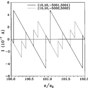
The spin-B interaction E(s,f) needs to be taken into account at large f, e.g.,f;100f0 ~or B;3 T!. The persis-tent currents including the Zeeman splitting are shown in Fig. 6 at 100f0<f<102f0 and T50. Compared with that in Fig. 3, the periodical oscillation is apparently destroyed by the inclusion of the spin-B interaction. As a result of
E(s,f), the energy of the spin-down state becomes lower, while that of the spin-up state becomes higher. The Zeeman splitting could make certain states cross the Fermi level at magnetic flux smaller (fc,2) and larger (fc,1) than fa.
The metal-semiconductor or semiconductor-metal transitions would occur more frequently, which thus induces more jump structures in the persistent current and destruction of the pe-riodicity.
FIG. 4. Same plot as Fig. 3, but shown for TCN’s with various radii. The persistent current of the ~20,20,25001,5001! TCN ~the open circles! is also shown to see the dependence on the toroid width.
A single jump at fa is replaced by a pair of jumps at
fc,7, which is related to the state crossing of the Fermi
level. The crossing positions fc,7 satisfy the condition
E(m,L,fc,7)5E(s,fc,7). An approximate fc,7 could be
obtained from expanding E(m,L,f) in the neighborhood of
fa, where L is equal to La5p/32fa/f0 or Lb52p/3
2fa/f0. fc,7is approximately given by
fc,7'
S
172gs
3bRg0m*
D
fa. ~8!The magnetic-flux region, in which a pair of jumps exist, is ;0.12f0forfa5101f0. The persistent current exhibits the special jumps atfc,7, since certain states become occupied or unoccupied in the increasing of f. Here we examine the jumps at fc,2, and the similar result is obtained for the
jumps at fc,1. The unfolded ~folded! spin-up state for
E(m,La,f),0@E(m,Lb,f),0# changes into an
unoccu-pied state, but the unfolded ~folded! spin-down state for
E(m,La,f).0@E(m,Lb,f).0# changes into an occupied
state. The former and the latter, respectively, carry current 2I0/4 and I0/4@Eqs. ~A4! and ~A5!#, so they cause a jump of
I0/2 at the crossing position. For the type I~type II TCN’s, the Laand Lb states would contribute to the jump of current
at the same ~different! position, as stated earlier. Hence the height of jumps, as seen in Fig. 6, is I0 and I0/2 for type I and II TCN’s separately. On the contrary, the persistent cur-rent is independent of the Zeeman splitting, if the magnetic flux is located outside the region confined by fc,2 and
fc,1. In summary, the persistent current linearly decreases
with magnetic flux, together with the special jumps. At large
f, it could be expressed by I~f!5I0
H
Cdf5fc,72 2~f2if0! f0J
for if0<f,~i11!f0, ~9! where C is 1 and 12 for type I and II TCN’s respectively.
Finally, the magnetic response in TCN’s is compared with that in SCN’s. They exhibit the similar magnetism at small
f. Carbon nanotubes, which are metals at f50, are para-magnetic, and the others are diamagnetic. On the other hand, the dependence on the nanotube radius, the temperature, and the Zeeman splitting might be different. The induced mag-netic moment in TCN’s is proportional to radius, while that in SCN’s is insensitive to radius.8–10The former is expected to be observable at T,10 K. Such a temperature is much lower than that (T,100 K) for the latter.10 The Zeeman ef-fect only causes the more jump structures in TCN’s; how-ever, it causes the special cusps in SCN’s. That DOS of TCN’s and SCN’s, respectively, diverges in d-function and 1/
A
E forms leads to the difference in special structures.10IV. CONCLUDING REMARKS
In this work, we have studied the electronic structure of the TCN’s, and investigated the persistent currents in them. The comparison with SCN’s and mesoscopic rings is also made.
The geometric structure determines the electronic struc-ture and thus the characteristics of the persistent currents. The electronic structure calculated from the tight-binding model could be divided into three kinds of type according to the geometric structure. Atf50, the type I, II, and III TCN’s are a metal, a narrow-gap semiconductor with Eg;1 meV,
and a wide-gap semiconductor with Eg;1 eV, respectively.
When TCN’s are threaded by a uniform perpendicular B field, the persistent currents only exist in the type I and II TCN’s. Such TCN’s would drastically change from metals ~semiconductors! into semiconductors ~metals! during the variation off.
The main features of the f-dependent persistent current include the periodical oscillation with a periodf0, the anti-symmetric structure about (i21/2)f0, the linear f -dependence, the special jump structures, and the weak mag-netic response. The periodical persistent current is the manifestation of the Aharonov-Bohm ~AB! effect. Type I TCN’s exhibit the paramagnetism at small f, which con-trasts greatly with the diamagnetism of type II TCN’s. The magnetic moment due to the persistent current is small, while it is much larger than that of a mesoscopic semicon-ductor or metal ring. The magnetic measurements5–7 could be used to verify the above mentioned characteristics.
The dependence of the persistent current on the toroid radius, the temperature, and the Zeeman splitting might be strong. The induced magnetic moment is found to be propor-tional to the toroid radius, but not the toroid width. On the other hand, the magnetic response of a SCN hardly depends on the radius.8–10 The persistent current could exist at T ,5 K. It would quickly decrease with an increase of T, however, temperature does not destroy the periodical AB oscillation. The Zeeman effect, which may lead to the de-struction of the periodicity and more jump structures, is ob-vious only at very largef. In short, a larger TCN at lower T andfis relatively suitable in verifying the AB effect.
If TCN’s are further connected by leads, they might dis-play the quantized ballistic transport properties.21 The elec-tronic structure will be directly reflected in the transport be-havior. The further theoretical and experimental studies on transport properties are very important.
FIG. 6. Same plot as Fig. 3, but the Zeeman splitting is taken into account.
ACKNOWLEDGMENTS
One of us ~M.F.L.! thanks C. Cheng for helpful discussions. This work was supported in part by the National Science Council of Taiwan, Republic of China under Grant Nos. NSC 87-2112-M-006-019 and NSC 87-2112-M-009-009.
APPENDIX
The f-dependent persistent current at T50 is calculated here. The persistent current in the armchair TCN is given by
I~f!armchair52c
(
s,J5m,L
2pg0sin@p~L1f/f0!/p#$7112 cos@p~L1f/f0!/p#%
pf0u172 cos@p~L1f/f0!/p#u
. ~A1!
The current is due to the electronic states of E(J5m,L,f) <0. The small-f expansion is used to evaluate I(f) at 0 <f,f0, i.e., sin
S
p~L1f/f0! pD
.sinS
pL pD
1 pf pf0 cosS
pL pD
, ~A2! cosS
p~L1f/f0! pD
.cosS
pL pD
1 pf pf0 sinS
pL pD
. ~A3! This approximate expansion is reasonable because ofpf/ pf0!1.
According to the denominator in Eq.~A1!, the various L states are divided into 1<L1f/f0,p/3, 2p/3<L 1f/f0, and p/3<L1f/f0,2p/3. For the 1<L1f/f0 ,p/3 states, the current of the unfolded state @2 in Eq. ~A1!# is the same with that of the folded state@1 in Eq. ~A1!#, and is given by 2I0
A
3H
sinS
pL pD
1 pf pf0 cosS
pL pDJ
. ~A4!The two spin states have been included in Eq.~A4!. Similar results are obtained for the 2 p/3<L1f/f0 states. The cur-rent carried by the unfolded or folded state is
I0
A
3H
sinS
pL pD
1 pf pf0 cosS
pL pDJ
. ~A5!But for the p/3,L1f/f0,2p/3 states, the unfolded and the folded states carry currents similar to Eqs.~A5! and ~A4!, respectively. The net current from these two states thus van-ishes.
The first terms in Eqs. ~A4! and ~A5! would cancel each other for the two states L and p2L except for the states
La1fa/f05p/3 and ~or! Lb1fa/f052p/3. The
signifi-cant cancellation is the principal cause of the weak magnetic response. On the other hand, the La and~or! Lb states, as
seen in Fig. 3, would induce a special jump of 2I0(I0) atfa for type I ~type II! TCN’s. Concerning the second terms in Eqs. ~A4! and ~A5!, the net current due to them is 22I0f/f0 after the summation of L’s. Hence the f -dependent persistent current declines at a rate22I0/f0 ex-cept atf’s, where the metal-semiconductor transitions occur. This feature remains unchanged even in the presence of the Zeeman splitting. In short, I(f) @Eq. ~7!# is a linear disper-sion relation, together with special jumps. While the Zeeman splitting is taken into account, the persistent current in the magnetic-flux region confined by fc,7 would change. The results in Eqs.~A4! and ~A5! could also be applied to under-stand the main change.
1S. Iijima, Nature~London! 354, 56 ~1991!. 2A. Thess et al., Science 273, 438~1996!.
3J. Liu, H. Dai, J. H. Hafner, D. T. Colbert, R. E. Samlley, S. J.
Tans, and C. Dekker, Nature~London! 385, 780 ~1997!.
4H. F. Cheung, Y. Gefen, E. K. Riedel, and W. H. Shih, Phys. Rev.
B 37, 6050~1988!.
5L. P. Levy, G. Dolan, J. Dunsmuir, and H. Bouchiat, Phys. Rev.
Lett. 64, 2074~1990!.
6V. Chandrasekhar, R. A. Webb, M. J. Brady, M. B. Ketchen, W.
J. Gallagher, and A. Kleinsasser, Phys. Rev. Lett. 64, 3578 ~1991!.
7D. Mailly, C. Chapelier, and A. Benoit, Phys. Rev. Lett. 70, 2020
~1993!.
8H. Ajiki and T. Ando, J. Phys. Soc. Jpn. 62, 2470~1993!; 64,
4382~1995!.
9J. P. Lu, Phys. Rev. Lett. 71, 1123~1995!.
10M. F. Lin and K. W.-K. Shung, Phys. Rev. B 52, 8423~1995!. 11B. I. Dunlap, Phys. Rev. B 46, 1933~1992!.
12S. Itoh, S. Ihara, and J. I. Kitakami, Phys. Rev. B 47, 1703
~1993!; 47, 12 908 ~1993!.
13P. R. Wallace, Phys. Rev. 71, 622~1947!.
14R. Saito, M. Fujita, G. Dresselhaus, and M. S. Dresselhaus, Appl.
Phys. Lett. 60, 2204~1992!; Phys. Rev. B 46, 1804 ~1992!.
15J. W. Mintwire, B. I. Dunlap, and C. T. White, Phys. Rev. Lett.
68, 631~1992!.
16N. Hamada, S. I. Sawada, and A. Oshiyama, Phys. Rev. Lett. 68,
1579~1992!.
17R. C. Haddon, Nature~London! 388, 31 ~1997!.
18D. H. Robertson, D. W. Brenner, and J. W. K. Mintmire, Phys.
Rev. B 45, 12 592~1992!.
19B. I. Dunlap, Phys. Rev. B 49, 5643~1994!.
20M. S. Dresselhaus and G. Dresselhaus, Adv. Phys. 30, 139
~1981!.
21R. Landauer, IBM J. Res. Dev. 1, 223~1957!; Philos. Mag. 21,