Phase Evolution in Silicon Carbide–Whisker-Reinforced
Mullite/Zirconia Composite during Long-Term
Oxidation at 1000° to 1350°C
Chien-Cheng Lin*
,†Department of Materials Science and Engineering, National Chiao Tung University, Hsinchu 300, Taiwan
Avigdor Zangvil*
Frederick Seitz Materials Research Laboratory and Department of Materials Science and Engineering, University of Illinois, Urbana, Illinois 61801
Robert Ruh*
,‡Air Force Research Laboratory, Wright–Patterson AFB, Ohio 45433 A composite consisting of 30 wt% SiC whiskers and a
mullite-based matrix (mullite–32.4 wt% ZrO2–2.2 wt% MgO) was
isothermally exposed in air at 1000°–1350°C, for up to 1000 h. Microstructural evolution in the oxidized samples was inves-tigated using X-ray diffractometry and analytical transmission electron microscopy. Amorphous SiO2, formed through the
oxidation of SiC whiskers, was devitrified into cristobalite at
T > 1200°C and into quartz at 1000°C. At T > 1200°C, the
reaction between ZrO2 and SiO2 resulted in zircon, and
prismatic secondary mullite grains were formed via a solution– reprecipitation mechanism in severely oxidized regions. Ter-nary compounds, such as sapphirine and cordierite, also were found after long-term exposure at T > 1200°C.
I. Introduction
C
ERAMIC-MATRIX composites toughened by SiC whiskers are possible candidates for use in high-temperature environ-ments.1–7Thus, the oxidation behavior of these composites at high temperatures is of great concern.8 –17
Previous studies6 –9,14,15
have indicated that the oxidation behavior and mechanical properties of SiC-whisker or particulate-reinforced ceramic-matrix composites are strongly affected by the reaction between the oxidation product (i.e., SiO2) and the matrix.
Porter and Chokshi6
and Becher and Tiegs7
suggested that the mechanical properties of SiC-whisker-reinforced Al2O3are related
to the oxidation of SiC whiskers and to the subsequent reaction of SiO2with the Al2O3matrix. Some studies
8 –10
revealed that the parabolic rate constants of SiC in an Al2O3or mullite matrix were
much higher than those expected for the oxidation of bulk SiC, because a liquid aluminosilicate phase was formed following the reaction between the oxidation product and the matrix. Tsai and co-workers15,16
reported that various oxidation modes were oper-ative in mullite/ZrO2/SiC composites, depending on the ZrO2
content. Those researchers also found that the oxidation mode
could be affected, because of the zircon formation, by the reaction between SiO2and ZrO2. However, very little detailed description
of the resultant microstructures and the oxide-formation mecha-nisms has been provided to date, even though such description is crucial to a full understanding of the oxidation behavior of composites with SiC reinforcements.
Recently, Lin et al.17
described the microscopic mechanisms of the oxidation of SiC whiskers in mullite-matrix and ZrO2
-containing mullite-matrix composites, mainly based on trans-mission electron microscopy (TEM) observations of individual oxidized SiC whiskers at various depths. Those studies focused on the early stages of oxidation, in locations where unoxidized SiC was still available.
The purpose of the present study is to explore the microstruc-tural variations caused by the interdiffusion and chemical reactions between the oxide product and the matrix during the long-term oxidation of SiC-whisker-reinforced mullite/ZrO2composites. The
microstructures of the oxidized samples of various composites after exposure in the temperature range 1000°–1350°C, for up to 1000 h in air, were studied using X-ray diffractometry (XRD), TEM, and energy-dispersive spectroscopy (EDS).
II. Experimental Procedure
The matrix of the composite was prepared by the sol– gel process, starting with the alkoxides of silicon, aluminum, zirco-nium, and magnesium. The matrix consisted of mullite–32.4 wt% ZrO2–2.2 wt% MgO. After 30 wt% SiC whiskers (Silar SC-9,
Arco Chemical Co., now Advanced Composite Materials Corp., Greer, SC), had been incorporated into the alkoxides, the mixtures were hot-pressed (Model No. 1–2300, Centorr Furnaces/Vacuum Industries, Inc., Nashua, NH) in graphite dies lined with graphite foil at 1400°C, under 34.5 MPa, for 20 min in an argon atmo-sphere. The crystalline phases (determined by XRD) of the hot-pressed samples included mullite, tetragonal and monoclinic ZrO2, SiC, and traces of spinel and zircon, as described by a
previous study.18
Composite samples measuring⬃10 mm ⫻ 6 mm ⫻ 3 mm were exposed isothermally in air, at temperatures ranging from 1000° to 1350°C, for up to 1000 h. Before exposure, all of the surfaces were ground on SiC sandpaper from 240 grit to 600 grit, in sequence, and polished with 3m diamond paste on nylon cloth. Samples were inserted into a box furnace (Model No. 51333, Lindberg Corp., St. Louis, MO) preheated to the desired temperature. The exposed samples, as well as the hot-pressed samples, were char-acterized by XRD, as described elsewhere.17
Both cross-sectional D. P. Butt—contributing editor
Manuscript No. 189432. Received April 8, 1999; approved November 1, 1999. Supported by the National Science Council, Taiwan, under Contract No. NSC87-2216-E-009-014.
*Member, American Ceramic Society.
†Author to whom correspondence should be addressed.
‡Presently at Universal Technology Corporation, Beavercreek, OH 45432.
1797
SiC whiskers were completely oxidized at the outer surface. At temperatures of⬎1200°C, the reaction of the oxide layer of SiC whiskers with the matrix produced new phases. The formation of ternary sapphirine and/or cordierite phases was caused by the reactions among MgO, Al2O3, and SiO2, while the reactions
between ZrO2and SiO2and between MgO and Al2O3resulted in
zircon and aluminum–magnesium spinel, respectively. The amor-phous background intensity at 20°ⱕ 2 ⱕ 30° in the XRD spectra at 1350°C for 260 or 1000 h was caused mainly by the amorphous aluminosilicate phase, formed through the reaction of SiO2, Al2O3,
and other impurities, while the background in the same angles from the sample after exposure at 1000° or 1350°C for 1 h was caused by the amorphous SiO2oxidation product.
(2) TEM Observation
(A) Devitrification of Silica: When SiC-whisker-reinforced mullite-matrix composites were exposed to high-temperature oxi-dizing environments, SiC whiskers in the outer region were oxidized via an oxygen-inward diffusion mechanism. The oxida-tion of SiC whiskers is expressed by the following reacoxida-tion:
SiC⫹3
2O2 3 SiO2共silica兲 ⫹ CO (1)
The oxidation product of SiC whiskers was amorphous SiO2.
However, after long periods, the amorphous SiO2devitrified into
various polymorphic forms of crystalline SiO2, depending on the
exposure conditions. Figure 1(a) shows several low-quartz grains, marked “Q,” in the composite after exposure at 1000°C for 1000 h. Presumably, those grains experienced the high3 low displacive transformation at⬃573°C when they were cooled to room tem-perature.20
Inset at the upper right corner of Fig. 1(a) is the selected area diffraction pattern (SADP) of quartz. The EDS analysis (not shown) revealed that these quartz grains usually contain a small amount of Al2O3in solid solution. At temperatures
ⱖ1200°C, cristobalite formed within the SiO2 layer. Figure 1(b)
shows the micrograph of low or␣-cristobalite, with its SADP inset at the upper right corner. Cristobalite was very unstable under the electron beam, presumably because of beam heating. Twins in
␣-cristobalite were caused by the  3 ␣ displacive transformation
at⬃200°–275°C.21–23
(B) Formation of Aluminum–Magnesium Spinel: As
men-tioned elsewhere,18
MgAl2O4spinel with stoichiometric
compo-sition uniformly existed in the matrix of the hot-pressed samples as separate (⬃0.2 m) grains. Figure 2 shows that a significantly larger amount of MgAl2O4spinel in the outer oxide layer of the
sample formed after exposure at 1200°C for 500 h. The formation of spinel required a sufficient amount of MgO, probably supplied by exsolution from the mullite matrix and/or long-range diffusion
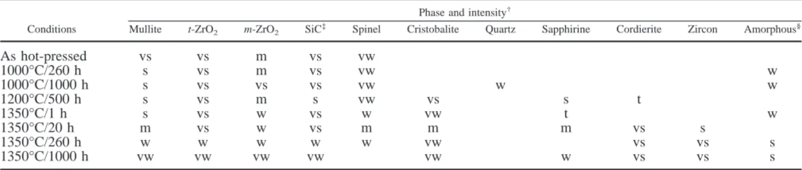
Table I. X-ray Diffraction Intensities for Various Phases in As-Hot-Pressed and Exposed Samples Conditions
Phase and intensity† Mullite t-ZrO2 m-ZrO2 SiC
‡ Spinel Cristobalite Quartz Sapphirine Cordierite Zircon Amorphous§
As hot-pressed vs vs m vs vw 1000°C/260 h s vs m vs vw w 1000°C/1000 h s vs vs vs vw w w 1200°C/500 h s vs m s vw vs s t 1350°C/1 h s vs w vs w vw t w 1350°C/20 h m vs w vs m m m vs s 1350°C/260 h w w w w w vw vs vs s 1350°C/1000 h vw vw vw vw vw w vs vs s
†vs⫽ very strong, s ⫽ strong, m ⫽ mediate, w ⫽ weak, vw ⫽ very weak, and t ⫽ trace.‡Including␣- and -SiC.§Recognized from the background intensity at 20°ⱕ 2 ⱕ 30°.
Fig. 1. (a) Quartz, marked “Q,” in the sample after exposure at 1000°C for1000 h (A⫽ (1210) and B ⫽ (0001) in the inset SADP) and (b) twinned
␣-cristobalite, marked “C,” in the sample after exposure at 1200°C for
across the sample. In the stoichiometric spinel, only one-eighth of the tetragonal interstitial sites and one-half of the octahedral interstitial sites were occupied. Therefore, a solid solution of various elements in spinel was expected. The solid solution of MgO in MgAl2O4 spinel was negligible, but an appreciable
amount of Al2O3was soluble. According to previous studies, 24 –26
the composition of the spinel had a wide range, from MgO䡠Al2O3
to Al2O3. Thus, the chemical formula of that spinel can be
expressed as MgO䡠nAl2O3. The formation of MgO䡠nAl2O3spinel
after exposure at Tⱖ 1200°C resulted from the reaction
MgO⫹ nAl2O3 3 MgO䡠nAl2O3共spinel兲 (2)
The aluminum–magnesium spinel had a very representative com-position of (in wt%) 23.2 MgO, 69.9 Al2O3, and 6.9 SiO2. This
composition corresponded to MgO䡠1.18Al2O3, with some SiO2in
solid solution. In contrast, no silicon was detected in the spinel by EDS analysis of the hot-pressed sample, as mentioned elsewhere.18
(C) Formation of Sapphirine: Because the XRD spectrum of sapphirine is very similar to that of MgAl2O4spinel, it is difficult
to distinguish between the two spectra by the XRD analysis only. However, sapphirine was easily recognized under TEM, as well as EDS, because of its special features. In the present study, sap-phirine was found in the samples after exposure at 1200°C for 500 h and at 1350°C for 1 h. The formation of sapphirine is related to the spinel by the following reaction:
2MgAl2O4共spinel兲 ⫹ SiO2共silica兲 3
2MgO䡠2Al2O3䡠SiO2共sapphirine兲 (3)
The 2:2:1 ratio is only approximate. The actual composition of sapphirine has a very wide range, which can be expressed by a general formula: Mg7Al22⫺xSi0.75xO40, with 1.5ⱕ x ⱕ 5.6.
27,28
In the present study, the composition of sapphirine was estimated using the Cliff–Lorimer method. The measured x value range was 2.8 – 4.8.
The most common polytypes in sapphirine are sapphirine–1Tc and sapphirine–2M. The former has a one-layered structure along
b*, with b⬇ 0.72 nm; the latter has a two-layered structure, with b⬇ 1.44 nm.29
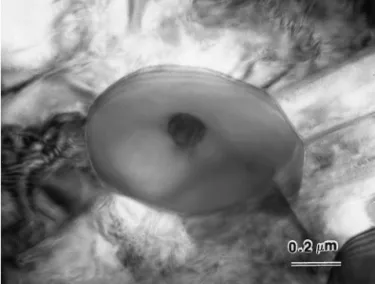
Figure 3(a) shows the image of the sapphirine in the composite after exposure at 1200°C for 500 h. The sapphirine had a characteristic needlelike shape, with the needle axis parallel to a*. Twin boundaries also were revealed. For convenience, the SADP of the sapphirine (inset in the upper right corner) was indexed as having a monoclinic unit cell. However, the unit cell was identified as triclinic twinned sapphirine–1Tc, with a (010) twin plane. The superlattice spots of l⫽ 2n ⫹ 1 were weaker than the basic spots of l ⫽ 2n. However, they displayed the true
periodicity of the unit cell along b* and the streaking caused by the stacking disorder.29
In the present study, high-resolution TEM techniques were attempted to explore the stacking sequence on an atomic scale, and the result indicated that the sapphirine found was basically the twinned 1Tc form (Fig. 3(b)).
Barbier and Hyde30
described sapphirine as a regular inter-growth at the unit-cell level of the slabs of the spinel and clinopyroxene structures. The ideal stoichiometric sapphirine can be written as follows:
Mg4Al8Si2O20共sapphirine兲 3
2MgAl2O4共spinel兲 ⫹ 2MgAl2SiO6共clinopyroxene兲 (4)
However, in the present cases, spinel was embedded in sapphirine, as shown in Figs. 4(a) and (c). Figure 4(a) is the bright-field image, and Fig. 4(c) displays the dark-field image obtained by the (220) diffracted spot of spinel. This image implies that spinel may be the precursor of sapphirine, as mentioned above. The SADP in Fig. 4(b) indicates that the orientation relationships between spinel and sapphirine are具110典sp储 具100典sapphand {110}sp储 {010}sapph.
In the present study, we also found that sapphirine structures were unstable under strong heating of the electron beam. The clinopyroxene became amorphous under the intensive electron-beam heating, and the spinel was simultaneously transformed into micrograins.
Fig. 2. Several spinel grains in the outer oxide layer of the sample after exposure at 1200°C for 500 h; inset SADP was in the [011] zone (A⫽ (022) and B⫽ (200)).
Fig. 3. (a) Needlelike sapphirine in the sample after exposure at 1200°C for 500 h; SADP was indexed as the monoclinic symmetry, for conve-nience, indicating the 1Tc structure in the [100]Mzone (A⫽ (020)Mand
B⫽ (012)M). (b) High-resolution micrograph, showing the sapphirine–1Tc
structure, with (010)Mtwin planes.
(D) Formation of Cordierite: There are two common poly-morphic forms of cordierite:31,32
high cordierite, with a hexagonal crystal structure, and low cordierite, with an orthorhombic crystal structure. The hexagonal-to-orthorhombic transformation involves the Al,Si ordering, which is characterized by the splitting of the (211) peak of the hexagonal cordierite into (151), (241), and (311) of the orthorhombic cordierite in the XRD spectrum. Distortion indexes,⌬, were defined by Miyashiro33
and measured by Putnis and co-workers,34,35
who found⌬ ⫽ 0 in the hexagonal cordierite and ⌬ ⬇ 0.25 in the orthorhombic cordierite, with intermediate values for the continuous Al,Si ordering sequence from high to low
study. The SADP in Fig. 5(d) shows the split diffraction spots caused by the low-angle (⬃2°) boundary. Spherical ZrO2particles
frequently were observed embedded in cordierite. The ZrO2acted
as a nucleating agent of cordierite, as is the case in the cordierite– ZrO2glass-ceramic system.
37–39
The sequence for the phase transformation of cordierite during oxidation at Tⱖ 1200°C can be described as follows: hexagonal cordierite 3 modulated hexagonal cordierite 3 orthorhombic cordierite. This sequence is consistent with the result reported by Putnis.34
At temperatures between 1050° and 1445°C, the first crystallization product of the stoichiometric magnesium– cordierite invariably was hexagonal cordierite, which eventually trans-formed, on annealing, to orthorhombic cordierite via an interme-diate modulated structure.
Cordierite grains had a rodlike appearance, presumably “inher-ited” from that of sapphirine, as shown in Fig. 5(c). The axes of the rodlike cordierite crystals in Fig. 5(c) are parallel to c*. This orientation implies that cordierite was formed from sapphirine, simply by the incorporation of additional SiO2, supplied by the
further oxidation of SiC whiskers. Thus, the formation of cordi-erite can be illustrated by the following reaction:
2MgO䡠2Al2O3䡠SiO2共sapphirine兲 ⫹ 4SiO2共silica兲
3 2MgO䡠2Al2O3䡠5SiO2共cordierite兲 (5)
(E) Formation of Anorthite: SiC whiskers contained
calcium-rich inclusions in the core region.18
CaO was produced by the oxidation of these calcium-rich inclusions; however, it did not exist in its free state in the exposed samples but was dissolved into the SiO2, a product of the oxidation of SiC whiskers. The melting
point of the SiO2 was lowered by dissolving CaO or other
impurities. This impurity-bearing liquid phase was retained as glassy phases after the samples had been cooled to room temper-ature. However, CaO and the aluminosilicates also could react to become anorthite (CaAl2Si2O8).
Anorthite has two or three polymorphic forms:40
it experiences the series of C13 I1 3P1 or I1 3 P1 transformations when cooled from melts to room temperature. The C13 I1 transforma-tion is caused by Al,Si ordering, whereas the I1 3 P1 is a displacive ordering of the Ca2⫹ cation at ⬃240°C. Twinned
anorthite grains, shown in Fig. 6, were found in the sample after exposure at 1200°C for 500 h. From the inset SADP, the grains were identified as P1 anorthite,41,42
with the twin plane parallel to (010). Different domains in the anorthite phase had a similar crystallographic orientation but with angle differences of several degrees (mosaic structure). Also shown in Fig. 6 is a glassy phase (marked “G”) abutting the anorthite and containing a significant amount of CaO.
(F) Formation of Zircon: Zircon formation was caused by
the reaction of ZrO2and the oxidation product, SiO2:
ZrO2⫹ SiO2 3 ZrSiO4共zircon兲 (6)
Figure 7 shows a zircon grain with an imbedded residual ZrO2
particle. The morphology of zircon and ZrO2suggests that zircon
Fig. 4. (a) Spinel grain embedded in sapphirine; (b) SADP from the area, including spinel and sapphirine, indicating that [110]sp 储 [100]sapphand
(110)sp储 (010)sapph (A⫽ (220)sp, B⫽ (220)sp, C⫽ (020)sapph, D ⫽
Fig. 5. (a) Hexagonal cordierite, marked “C,” in the sample after exposure at 1200°C for 500 h; (b) modulated cordierite in the sample after exposure at 1350°C for 260 h; (c) orthorhombic cordierite in the sample after exposure at 1350°C for 1000 h; (d) SADP of the orthorhombic cordierite in (c) (A⫽ (020) and B⫽ (002)).
Fig. 6. Anorthite (marked “An”) in the sample after exposure at 1200°C for 500 h; SADP was identified as a mixture of C1 anorthite and P1 anorthite, with the twin plane parallel to (010) (A⫽ (020) and B ⫽(022); region marked “G” is a glassy phase).
Fig. 7. Zircon grain with an embedded residual ZrO2particle in the
sample after exposure at 1350°C for 1000 h. 2
formation is caused by inward diffusion of the Si4⫹. The formation
mechanism of zircon is described as follows:43,44
(1) Silica diffuses to the surface of ZrO2.
(2) Zircon forms, according to the chemical reaction in Eq. (6).
(3) Silicon and oxygen diffuse inward through the zircon layer to the interface of zircon and ZrO2, where the reaction continues.
Zircon was found only in samples exposed at temperatures
ⱖ1200°C. At T ⫽ 1000°C, the diffusion rate of SiO2was too low
for any appreciable reaction between ZrO2and SiO2.
The residual ZrO2 particle in zircon suggests an incomplete
reaction between ZrO2and SiO2; thus, the silicon diffusion rate in
zircon probably is very slow, even at 1350°C. The low diffusion rate in zircon can be explained by the dense crystal structure of zircon, which consists of four zirconium atoms and four SiO4
tetrahedra in a unit cell. Zircon forms at the expense of zirconia, a high-diffusivity path of oxygen. This reaction explains why the oxidation rate of composites could dramatically decrease follow-ing the formation of zircon.15,16
Consequently, prismatic secondary mullite grains formed only near the severely oxidized surface.
(3) Transformation Routes in the MgO–Al2O3–SiO2Phase Diagram
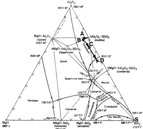
Significant compositional changes, which occurred in the oxi-dized regions of the composites, had an effect on the long-term oxidation of the composites. The transformation routes followed during the long-term oxidation of SiC-whisker-reinforced mullite/ MgO–partially stabilized ZrO2 composites can be described as
follows. The original matrix was composed of mullite (3Al2O3䡠2SiO2), spinel (MgAl2O4), and a small amount of
sap-phirine. The composition is designated point A in the Al2O3–
SiO2–MgO ternary phase diagram, as shown in Fig. 9, and is
located very close to the alkemade line connecting mullite and spinel. On the surface of the exposed sample, the amount of SiO2
increased because of the oxidation of SiC whiskers; MgO was enriched by long-range diffusion or exsolution from mullite grains. Thus, the composition moved from points A to B, located inside the spinel–sapphirine–mullite triangle.
This movement from point A to point B indicates that spinel and sapphirine are two predominant oxidation products in the early stage, as observed earlier. Then, with the approximately fixed ratio of Al2O3and MgO, further increase in SiO2made the composition
move along the line BS. Depending on the extent of oxidation, two
Fig. 8. Prismatic secondary mullite formed in the sample after exposure at 1350°C for 1000 h.
different situations could occur: If the new composition was point C inside the mullite– cordierite–sapphirine triangle, then sap-phirine and cordierite would coexist in the oxide layer, as in the sample exposed at 1250°C for 500 h. With further oxidation of the SiC whiskers, the composition would shift to point D inside the mullite– cordierite–silica triangle. Thus, cordierite would be the only MgO–Al2O3–SiO2compound in the severely oxidized
sur-face, as in the sample exposed at 1350°C for 1000 h.
IV. Conclusions
(1) In the exposed samples, amorphous SiO2formed because
of the oxidation of SiC whiskers. After extended exposure, the amorphous SiO2 devitrified into cristobalite at T ⱖ 1200°C or
quartz at lower temperatures.
(2) The matrix was stable at 1000°C. At Tⱖ 1200°C, the reaction between ZrO2and SiO2resulted in zircon, and prismatic
secondary mullite grains seemed to form via the solution– reprecipitation mechanism in the severely oxidized samples.
(3) During exposure at T ⱖ 1200°C, the reaction between MgO and Al2O3produced an aluminum–magnesium spinel.
Fur-ther addition of SiO2 to the spinel caused the formation of
sapphirine and/or cordierite.
(4) The significant compositional changes, which occurred in the oxidized regions of the composites, clearly affected the long-term oxidation of the composites.
References
1G. C. Wei and P. F. Becher, “Development of SiC-Whisker-Reinforced Ceram-ics,” Am. Ceram. Soc. Bull., 64 [2] 298–304 (1985).
2N. Claussen and G. Petzow, “Whisker-Reinforced Zirconia-Toughened Ceram-ics”; pp. 649 – 62 in Tailoring Multiphase and Composite Ceramics. Edited by R. E. Tressler, G. L. Messing, C. G. Pantano, and R. E. Newnham. Plenum Press, New York, 1986.
3R. Ruh, K. S. Mazdiyasni, and M. G. Mendiratta, “Mechanical and Microstruc-tural Characterization of Mullite and Mullite–SiC-Whisker and ZrO2-Toughened Mullite–SiC-Whisker Composites,” J. Am. Ceram. Soc., 71 [6] 503–12 (1988).
4P. F. Becher, C. H. Hsueh, P. Angelini, and T. N. Tiegs, “Toughening Behavior in Whisker-Reinforced Ceramic-Matrix Composites,” J. Am. Ceram. Soc., 71 [12] 1050 – 61 (1988).
5M. I. Osendi, B. A. Bender, and D. Lewis III, “Microstructure and Mechanical Properties of Mullite–Silicon Carbide Composites,” J. Am. Ceram. Soc., 72 [2] 1049 –54 (1989).
6J. R. Porter and A. H. Chokshi, “Creep Performance of Silicon Carbide–Whisker-Reinforced Alumina”; pp. 919 –28 in Ceramic Microstructure ‘86: Role of Interface. Edited by J. A. Pask and A. G. Evans. Plenum Press, New York, 1987.
7P. F. Becher and T. N. Tiegs, “Temperature Dependence of Strengthening by Whisker Reinforcement: SiC-Whisker-Reinforced Alumina in Air,” Adv. Ceram.
Mater., 3 [2] 148 –53 (1988).
8M. P. Borom, M. K. Brun, and L. E. Szala, “Kinetics of Oxidation of Carbide and Silicide Dispersed Phases in Oxide Matrices,” Adv. Ceram. Mater., 3 [5] 491–97 (1988).
9K. L. Luthra and H. D. Park, “Oxidation of Silicon Carbide–Reinforced Oxide-Matrix Composites at 1375° to 1575°C,” J. Am. Ceram. Soc., 73 [4] 1014 –23 (1990). 10M. I. Osendi, “Oxidation Behavior of Mullite–SiC Composites,” J. Mater. Sci.,
25, 3561– 65 (1990).
11H. Y. Liu, K. L. Weisskopf, M. J. Hoffmann, and G. Petzow, “Oxidation Behavior of SiC-Whisker-Reinforced Mullite (–ZrO2) Composites,” J. Eur. Ceram. Soc., 5, 122–33 (1989).
12C. Baudin and J. S. Moya, “Oxidation of Mullite–Zirconia–Alumina–Silicon Carbide Composites,” J. Am. Ceram. Soc., 73 [5] 1417–20 (1990).
13M. Backhaus-Ricoult, “Oxidation Behavior of SiC-Whisker-Reinforced Alu-mina–Zirconia Composites,” J. Am. Ceram. Soc., 74 [8] 1793– 802 (1991).
14C. C. Lin, A. Zangvil, and R. Ruh, “Modes of Oxidation in SiC-Reinforced Mullite/ZrO2-Based Composites: Oxidation versus Depth Behavior,” Acta Mater., 47 [6] 1977– 86 (1999).
15C. Y. Tsai, C. C. Lin, A. Zangvil, and A. K. Li, “Effect of Zirconia Content on the Oxidation Behavior of Silicon Carbide/Zirconia/Mullite Composites,” J. Am.
Ceram. Soc., 81 [9] 2413–20 (1998).
16C. Y. Tsai and C. C. Lin, “Dependence of Oxidation Modes on Zirconia Content in Silicon Carbide/Zirconia/Mullite Composites,” J. Am. Ceram. Soc., 81 [12] 3150 –56 (1998).
17C. C. Lin, A. Zangvil, and R. Ruh, “Microscopic Mechanisms of Oxidation in SiC-Whisker-Reinforced Mullite/ZrO2-Matrix Composites,” J. Am. Ceram. Soc., 82 [10] 2833– 40 (1999).
18A. Zangvil, C. C. Lin, and R. Ruh, “Microstructural Studies in Alkoxide-Derived Mullite/Zirconia/Silicon Carbide-Whisker Composites,” J. Am. Ceram. Soc., 75 [5] 1254 – 63 (1992).
19G. Cliff and G. W. Lorimer, “The Quantitative Analysis of Thin Specimens,” J. Microsc. (Oxford), 103 [2] 203–207 (1975).
20G. van Tendeloo, J. van Landuyt, and S. Amelinckx, “The ␣ 3  Phase Transition in Quartz and AlPO4, as Studied by Electron Microscopy and Diffraction,” Phys. Status Solidi A, 33 [2] 723–35 (1976).
21D. R. Peacor, “High-Temperature Single-Crystal Study of the Cristobalite Inversion,” Z. Kristallogr., 138, 274 –98 (1973).
22R. L. Withers, J. G. Thompson, and T. R. Welberry, “The Structure and Microstructure of␣-Cristobalite and Its Relationship to Cristobalite,” Phys. Chem.
Miner., 16 [6] 517–23 (1989).
23G. L. Hua, T. R. Welberry, R. L. Withers, and J. G. Thompson, “An Electron Diffraction and Lattice-Dynamical Study of the Diffuse Scattering in-Cristobalite, SiO2,” J. Appl. Crystallogr., 21 [5] 458 – 65 (1988).
24C. C. Wang and P. J. Zanzucchi, “Dielectric and Optical Properties of Stoichio-metric Magnesium Aluminate Spinel Single Crystals,” J. Electrochem. Soc., 118 [4] 586 –91 (1971).
25M. Ishii, J. Hiraishi, and T. Yamanaka, “Structure and Lattice Vibrations of Mg-Al Spinel Solid Solution,” Phys. Chem. Miner., 8 [2] 64 – 68 (1982).
26H. Suematsu, T. Suzuki, T. Iseki, and T. Mori, “Decoration of Dislocations by the Precipitation of Alumina in MgO–2.9Al2O3Spinel,” J. Am. Ceram. Soc., 72 [8] 1449 –52 (1989).
27R. M. Smart and F. P. Glasser, “The Subsolidus Phase Equilibria and Melting Temperatures of MgO–Al2O3–SiO2Composites,” Ceram. Int., 7 [3] 90 –97 (1981). 28F. C. Bishop and R. C. Newton, “The Composition of Low-Pressure Synthetic Sapphirine,” J. Geol., 83 [4] 511–17 (1975).
29A. G. Christy and A. Putnis, “Planar and Line Defects in the Sapphirine Polytypes,” Phys. Chem. Miner., 15 [6] 548 –58 (1988).
30J. Barbier and B. G. Hyde, “Structure of Sapphirine: Its Relation to the Spinel, Clinopyroxene, and-Gallia Structures,” Acta Crystallogr., Sect. B: Struct. Sci., B44 [4] 373–77 (1988).
31G. V. Gibbs, “The Polymorphism of Cordierite: I. The Crystal Structure of Low Cordierite,” Am. Mineral., 51 [7] 1068 – 87 (1966).
32E. P. Meagher and G. V. Gibbs, “The Polymorphism of Cordierite: II. The Crystal Structure of Indialite,” Can. Mineral., 15 [1] 43– 49 (1977).
33A. Miyashiro, “Cordierite–Indialite Relation,” Am. J. Sci., 255 [1] 4362 (1957). 34A. Putnis, “The Distortion Index in Anhydrous Mg-Cordierite,” Contrib. Min-eral. Petrol., 74 [2] 135– 41 (1980).
35A. Putnis and D. L. Bish, “The Mechanism and Kinetics of Al,Si Ordering in Mg-Cordierite,” Am. Mineral., 68 [1] 60 – 65 (1983).
36H. L. M. van Roermund and R. J. Konert, “Deformation and Recrystallization Mechanisms in Naturally Deformed Cordierite,” Phys. Chem. Miner., 17 [1] 52– 61 (1990).
37W. Zdaniewski, “DTA and X-ray Analysis Study of Nucleation and Crystalliza-tion of MgO–Al2O3–SiO2Glasses Containing ZrO2, TiO2, and CeO2,” J. Am. Ceram. Soc., 58 [5– 6] 163– 69 (1975).
38G. F. Neilson, “Nucleation and Crystallization in ZrO
2-Nucleated Glass-Ceramic System”; pp. 78 – 82 in Advances in Nucleation and Crystallization in Glasses. Edited by L. L. Hench and S. W. Freiman. American Ceramic Society, Columbus, OH, 1971. 39T. I. Barry, J. M. Cox, and R. Morrell, “Cordierite Glass-Ceramics: Effect of TiO2and ZrO2Content on Phase Sequence during Heat Treatment,” J. Mater. Sci., 13 [3] 594 – 610 (1978).
40A. H. Heuer and G. L. Nord Jr., “Polymorphic Phase Transitions in Minerals”; pp. 271–303 in Applications of Electron Microscopy in Mineralogy. Edited by H. R. Wenk. Springer-Verlag, Berlin, Germany, 1976.
41J. Copreaux, M. Gandais, and S. C. Duion, “Growth and Ordering Processes in Synthetic Hydrothermal Anorthite,” Phys. Chem. Miner., 16 [6] 545–50 (1989).
42G. van Tendeloo, S. Ghose, and S. Amelinckx, “A Dynamic Model for the P13 I1 Phase Transition in Anorthite, CaAl2Si2O8: I. Evidence from Electron Microsco-py,” Phys. Chem. Miner., 16 [4] 311–19 (1989).
43K. M. Trappen and R. A. Eppler, “Reaction of Zirconia with Silica at the Stoichiometry of Zircon,” J. Am. Ceram. Soc., 72 [6] 882– 85 (1989).
44R. A. Eppler, “Mechanism of Formation of Zircon Stains,” J. Am. Ceram. Soc.,
53 [8] 457– 62 (1970).
45P. Drew and M. H. Lewis, “The Microstructures of Silicon Nitride Ceramics during Hot-Pressing Transformations,” J. Mater. Sci., 9 [21] 261– 69 (1974).
46M. H. Lewis, B. D. Powell, P. Drew, R. J. Lumby, B. North, and A. J. Taylor, “The Formation of Single-Phase Si-Al-O-N Ceramics,” J. Mater. Sci., 12 [1] 61–74
(1977). 䡺
![Fig. 3. (a) Needlelike sapphirine in the sample after exposure at 1200°C for 500 h; SADP was indexed as the monoclinic symmetry, for conve-nience, indicating the 1Tc structure in the [100] M zone (A ⫽ (020) M and](https://thumb-ap.123doks.com/thumbv2/9libinfo/7752304.148806/3.918.102.476.44.320/needlelike-sapphirine-exposure-indexed-monoclinic-symmetry-indicating-structure.webp)