行政院國家科學委員會專題研究計畫 期中進度報告
超寬頻無線通訊系統在智慧型天線通道上之性能研究(2/3)
計畫類別: 個別型計畫
計畫編號: NSC94-2213-E-009-030-
執行期間: 94 年 08 月 01 日至 95 年 07 月 31 日
執行單位: 國立交通大學電信工程學系(所)
計畫主持人: 王蒞君
報告類型: 精簡報告
報告附件: 出席國際會議研究心得報告及發表論文
處理方式: 本計畫可公開查詢
中 華 民 國 95 年 5 月 3 日
行政院國家科學委員會補助專題研究計畫期中進度報告
超寬頻無線通訊系統在智慧型天線通道上之性能研究
計畫類別:個別型計畫
計畫編號:NSC 94-2213-E-009-030
執行期間:94 年 8 月 1 日至 95 年 7 月 31 日
計畫主持人:王蒞君 教授
共同主持人:
計畫參與人員:劉維正
成果報告類型(依經費核定清單規定繳交):精簡報告
本成果報告包括以下應繳交之附件:
□赴國外出差或研習心得報告一份
□赴大陸地區出差或研習心得報告一份
□出席國際學術會議心得報告及發表之論文各一份
□國際合作研究計畫國外研究報告書一份
處理方式:除產學合作研究計畫、提升產業技術及人才培育研究計畫、
列管計畫及下列情形者外,得立即公開查詢
□涉及專利或其他智慧財產權,□一年□二年後可公開查詢
ˇ
執行單位:國立交通大學電信工程學系
中 華 民 國 95 年 5 月 3 日
II
摘要
本年度的研究計劃之研究成果可分為兩大部份:
一、在具有隨機群集及射線特性的高度頻率選擇性衰減通道下以脈波為基礎之超寬頻系統
效能分析
在這一部份我們推導出在 IEEE 802.15.3a 通道下,二元信號的位元錯誤率。雖然
IEEE 802.15.3a 通道已經被廣泛地採用,但是在這樣的通道下,超寬頻系統的效能評估大
多是以模擬代替分析的方式來達成。在這類的超寬頻通道中所具有的獨特的群集 (cluster)
特性及高密度的多重路徑效應使得效能的分析變得有趣但也富有挑戰性。以數學的角度來
看,在這樣的通道下的信號可視為一個聯合對數常態 (lognormal) 和帕松的隨機信號。其
中信號振幅的衰減是以對數常態隨機變數來描述,而群集效應是以帕松隨機變數來描述。
我們發展了一套計算位元錯誤率的方法,把所有 IEEE 802.15.3a 通道的參數都考慮進
去,包括了群集/射線抵達率 (ray arrival rate),群集/射線衰退因子 (decay factor),每個群
集所包含的射線數目,對數常態衰減和對數常態遮蔽效應。此外,耙式接收器 (RAKE
receiver) 的耙齒數目也列入考慮。
二、在 IEEE 802.15.4a 通道下之耙式接受器之位元錯誤率分析
此一部分提供了在超寬頻通道下,應用耙式接收器接收反極 (antipodal) 和正交二元
信號之位元錯誤率分析。我們提供了一個位元錯誤率的分析數學式以及計算的公式。我們
考慮的通道模型是 IEEE 802.15.4a 通道。我們研究了所有參數所造成的影響,包括了群
集抵達率,群集衰退常數 (cluster decay constant),射線間抵達率 (inter-ray arrival rate),射
線衰退常數 (ray decay constant),功率延遲模型 (power delay profile, PDP) 的參數,以及
中上 (Nakagami) 衰減信號的分佈。對於 IEEE 802.15.4a 超寬頻通道而言,群集效應是以
帕松隨機程序來描述,而射線間抵達時間是以超對數隨機變數來描述。我們提出了一個系
統化的分析方法來評估超寬頻信號在這樣的一個跟連續的中上以及離散的帕松隨機變數有
關的機率模型之下,它的數學統計特性。所以,我們所發展出來的分析模型可以有效率地
計算出一個超寬頻信號在 IEEE 802.15.4a 通道下的位元錯誤率,來取代耗時的電腦程式
模擬。
關鍵字:超寬頻 (Ultra-Wideband, UWB),IEEE 802.15.3a 通道模型,IEEE 802.15.4a 通
道模型,位元錯誤率 (bit error rate, BER)。
研究成果
第一部份的研究成果的一部份已發表至 IEEE Vehicular Technology Conference 2006
Spring [1],完整的版本已投稿至 IEEE Transactions on Vehicular Technology [2]。第二部份
的研究成果亦已被 IEEE Vehicular Technology Conference 2006 Fall [3] 所接受。詳見附
件。
III
[1] Wei-Cheng Liu and Li-Chun Wang, “Performance analysis of pulse based ultra-wideband
systems in the highly frequency selective fading channel with cluster property,” to appear in
IEEE Vehicular Technology Conference 2006 Spring.
[2] Wei-Cheng Liu and Li-Chun Wang, “Performance analysis of pulse based ultra-wideband
systems in the highly frequency selective fading channel with random clusters and rays,”
submitted to IEEE Transactions on Vehicular Technology.
[3] Wei-Cheng Liu and Li-Chun Wang, “BER analysis of the IEEE 802.15.4a channel model with
RAKE receiver,” accepted by IEEE Vehicular Technology Conference 2006 Fall.
Performance Analysis of Pulse Based
Ultra-Wideband Systems in the Highly Frequency
Selective Fading Channel with Cluster Property
Wei-Cheng Liu and Li-Chun Wang
Department of Communication Engineering
National Chiao Tung University, Hsinchu, Taiwan
[email protected], Tel: +886-3-5712121 ext 54511
Abstract— This paper presents an analytical expression for the
bit error rate (BER) of the antipodal and orthogonal binary sig-nals in the ultra-wideband (UWB) channel, of which the unique characteristics include the cluster property and highly dense multipath effect. Specifically, we consider the IEEE 802.15.3a UWB channel and take into account of the impact of all the key parameters, consisting of the cluster arrival rate, cluster decay factor, the number of rays per cluster, and the distribution of a non-Rayleigh fading signal. For the IEEE 802.15.3a UWB channel, the effects of clustering are characterized by a Poisson discrete random variable, and the magnitude of the signal is modelled by lognormal random variable. In this paper, we develop an analytical model to compute the signal with such joint continuous lognormal and discrete Poisson random variable. Hence, the developed analytical model can be useful in evaluating the performance of an UWB signal in the IEEE 802.15.3a channel without time consuming simulations.
Index Terms— Ultra-wideband (UWB), IEEE 802.15.3a
chan-nel model, bit error rate (BER).
I. INTRODUCTION
W
IRELESS systems continue pursuing even higher data rates and better quality. The ultra-wideband (UWB) is a promising technique to achieve this objective. Performance analysis of the UWB communication system in a realistic UWB channel is important but not an easy task.In this work, we consider the IEEE 802.15.3a UWB channel model [1]. Two important properties distinguish the UWB channel from the conventional narrow band channel. First, the bandwidth of the UWB signals is much wider than the co-herence bandwidth of the channel. Thus, in the frequency do-main the extremely highly frequency selective fading occurs. Second, in the time domain the extremely large bandwidth leads to high resolution arrival time for the UWB signal. Thus, the reflected UWB waves by objects usually yield a number of clusters of rays, which may contain some non-Rayleigh multipath components.
A. Motivation
The challenges of analyzing UWB signals lie in three folds.
• First, unlike the narrow band channel model that usually
has only one cluster with a fixed-number of arrival rays,
1This work is supported by the National Science Council, Taiwan, under
the contract NSC94-2213-E-009-030.
the transmitted signal over the UWB channel may arrive in many clusters, of which the number of arrival rays is also random. Mathematically, the arrival process of the UWB signal is modelled by a doubly stochastic Poisson process. The collected signal energy at the RAKE receiver in a channel with unknown number of rays is difficult to be analyzed.
• The amplitude of the impulse response in the UWB
chan-nel is a joint two-dimension random variable, consisting of the lognormally faded amplitude with a mean related to two Erlang random variables. This is because the average of the channel impulse is also a random variable due to varying interarrival time of rays and clusters.
• Due to insufficient arrival rays in a very narrow time
bin, the central limit theorem is no longer true. Thus, the multipath fading signal is not a traditional Rayleigh random variable. In the IEEE 802.15.3a UWB channel, the multipath fading signal is characterized by a lognor-mal random variable according to measurement results. Furthermore, shadowing is also considered in the IEEE 802.15.3a channel model. Thus, for a given number of rays and the mean of the signal amplitude, a UWB signal is a composite slowly varying lognormally shadowed/fast-varying lognormally faded random variable. The analysis of such a signal is rarely seen in current literature. The IEEE 802.15.3a UWB channel model defines four sets of parameters for different environments. Based on this channel model, a UWB signal can be characterized by a joint continuous lognormal and discrete doubly stochastic Poisson random variable, of which key parameters include the cluster/ray arrival rates, the cluster/ray decay factors, the standard deviations of the lognormal fading.
To our knowledge, a complete analytical formula for the bit error rate (BER) performance with RAKE receiver in the IEEE 802.15.3a UWB channel considering all the three aforementioned challenges and key parameters is not seen in the literature.
B. Related Work
The published papers which are related to the performance analysis of the UWB system under different channels are listed as follows. In [2], the authors derived the theoretical BER
of binary and M-ary UWB systems with Walsh codes under the AWGN channel with multiple access interference. In [3], the authors studied the performances of UWB systems in the AWGN channel in the presence of the interference from uni-versal mobile telecommunications system (UMTS)/wideband code division multiple access (WCDMA) band is present. The BER performances of the UWB system were derived under the flat and dispersive Rayleigh fading channels with timing jitter in [4]. In [5], the authors analyzed the performance of a transmit-reference (TR) UWB system with a simple autocorrelation receiver under a slow fading channel of which attenuations are characterized by an appropriate moment gen-erating function.
In [6], the authors derived a BER formula for the IEEE 802.15.3a UWB channel model but only as a function of finite window size rather than a function of the fingers number of the RAKE receiver. In [7], they further obtained statistics of the output SNR for the RAKE receiver in the IEEE 802.15.3a UWB channel, but without providing explicit BER formula and ignored the shadowing effect.
C. Objective and Outline of This Paper
The objective of this paper is to derive the analytical BER expression for the UWB system using the coherent RAKE receiver in a complete IEEE 802.15.3a UWB channel. The difference between [6] and [7] and our work are two folds. First, we consider the lognormal shadowing fading in the IEEE 802.15.3a channel model. Second, we derive the BER formula as a function of the fingers number of the RAKE receiver in the UWB channel. From the numerical results, we can see that BER in the IEEE 802.15.3a channel can be analyzed and approach the simulation results.
The rest of this paper is organized as follows. Section II describes the IEEE 802.15.3a channel model. In Section III, we derive the evaluation-form expression for BER of the binary signals subject to the impact of the considered UWB channel. Section IV shows our numerical results. Last, we give our conclusions in Section V.
II. CHANNELMODEL
We consider the UWB channel model in [1]. The impulse response of the channel model is
hi(t) = Xi NXc−1 l=0 NXr−1 k=0 αi k,lδ(t − Tli− τk,li ), (1)
where i refers to the i-th realization, {Xi} represents the
lognormal shadowing [i.e., 20 log(Xi) ∝ Normal(0, σx2)],
{αi
k,l} are the multipath gain coefficients, {Tli} is the delay
of the l-th cluster, {τi
k,l} is the delay of the k-th multipath
component relative to the l-th cluster arrival time (Ti l), Nc is
the number of clusters, and Nris the number of rays for each
cluster. By definition, we have τ0,l = 0.
The distribution of cluster arrival time and the ray arrival time are given by
p(Tl|Tl−1) = Λ exp[−Λ(Tl− Tl−1)] (2)
and
p(τk,l|τ(k−1),l) = λ exp[−λ(τk,l− τ(k−1),l)] (3)
where Λ and λ are the cluster and ray arrival rate, respectively. Note that T0= 0 in the line-of-sight (LOS) channel, while in
the non-line-of-sight (NLOS) channel, T0 is an exponential
random variable. That is,
p(T0) = Λ exp(−ΛT0). (4)
The channel coefficients (αk,l) are defined as follows:
αk,l= pk,lξlβk,l, (5)
where pk,l is equiprobable ±1 to account for signal inversion
due to reflections, ξl reflects the fading associated with the
l-th cluster, and βk,l corresponds to the fading associated with
the k-th ray of the l-th cluster. The total energy contained in the terms {αk,l} is normalized to unity for each realization.
The distribution of ξlβk,l is
20 log(ξlβk,l) ∝ Normal(µk,l, σ12+ σ22) (6)
or
|ξlβk,l| = 10(µk,l+n1+n2)/20, (7)
where n1 ∝ Normal(0, σ12) and n2 ∝ Normal(0, σ22) are
independent and correspond to the fading on each cluster and ray, respectively. Note that
µk,l=10 ln(Ω0) − 10Tl/Γ − 10τk,l/γ ln(10) − (σ2 1+ σ22) ln(10) 20 (8) and E[|ξlβk,l|2] = Ω0e−Tl/Γe−τk,l/γ, (9)
where Ω0is the mean energy of the first path of the first cluster
and Tlis the excess delay of bin l. Γ is the cluster decay factor
and γ is the ray decay factor.
In [1], through measurements, some initial parameters are given for four kinds of channel models, namely CM1, CM2, CM3, and CM4, which are based on LOS 4 m), NLOS (0-4 m), NLOS ((0-4-10 m), and 25 nsec root-mean-square (RMS) delay spread channel measurements, respectively.
III. BER ANALYSIS
A. Receiver Structure
We use a coherent RAKE receiver with L fingers. The received SNR γb is γb= Eb N0 L X k=1 a2 k = L X k=1 γk, (10)
where Eb/N0is the bit SNR, ak is the channel amplitude that
appears at the k-th finger of the RAKE receiver. From [8] we know that the conditional error probability for binary signals for the coherent RAKE receiver is
P2(γb) = Q
³p
γb(1 − ρr)
´
(11) where ρr = −1 for antipodal signals and ρr = 0 for
orthogonal signals. Next we will derive the characteristic function of the received energy E , PLk=1a2
k in the UWB
B. Characteristic Function of the Received Energy (E)
In the following theorem, we give the formula of the characteristic function of E. We exploit the result in [9] to further take the number of fingers of the RAKE receiver (L), the chip duration between two fingers (Tc), and shadowing
into account. Importantly, instead of deriving the path gain of the UWB channel, we obtain directly the square of a path gain of a UWB channel, which can facilitate the BER calculation of the RAKE receiver in the UWB channel.
Corollary 1: Let LT,t(ν) be the characteristic function of
the single path gain in the IEEE 802.15.3a UWB channel with the cluster arrival time at T and the ray arrival time at t =
T + τ . Also, denote e−λψν(T ) and e−ΛJ(ν) the characteristic
function of a shot-noise random variable related to the ray arrival process with parameter λ and that related to the cluster arrival process with parameter Λ, respectively. Then, it can be proved that the characteristic function of the received energy (E) in the IEEE 802.15.3a UWB channel can be computed by Ψ(ν) = L0,0(ν)e−λψν(0)−ΛJ(ν). (12)
Proof: See [9].
Theorem 1: Consider a RAKE receiver with L fingers in
the IEEE 802.15.3a UWB channel. The characteristic function
LT,t(ν) can be computed by LT,t(ν) = Z ∞ 0 ejνx10 exp h − 1 8σ2 E(20 log10x − 2µT,t) 2i √ 2πσEx ln 10 dx ≈ N(H) X l=1 w(H)l √1 πexp µ jν10 √ 2σE x(H)l +µT,t 10 ¶ (13) where µT,t = ln 1010 h ln Ω0−TΓ −t−Tγ − ¡ln 10 10 ¢2 σ2 E 2 i and σE = p σ2
1+ σ22+ σ2x. The parameters Ω0, Γ, and γ are
defined in (9). Note that σE consists of σ1, σ2, and σx, which
represent the standard deviation of cluster fading, ray fading, and lognormal shadowing fading terms, respectively. {w(H)l }
and {x(H)l } are the weights and abscissas of the Gauss-Hermite
formula, respectively. N(H) is the number of points of the
Gauss-Hermite integration.
Proof: See Appendix I.
Theorem 2: For the RAKE receiver with L fingers, the
function ψν(T ) in (12) can be computed by
ψν(T ) = (R(L−1)Tc T [1 − LT,t(ν)]dt, T ≤ (L − 1)Tc, 0, T > (L − 1)Tc, ≈ (L−1)Tc−T 2 PN(L) p=1wp(L)[1 − LT,t(ν)] ¯ ¯ t=(L−1)Tc−T2 x(L) p+(L−1)Tc+T2 , T ≤ (L − 1)Tc, 0, T > (L − 1)Tc, (14)
where Tcis the chip duration between two fingers, {w(L)p } and
{x(L)
p } are the weights and abscissas of the Gauss-Legendre
formula, respectively. N(L) is the number of points of the
Gauss-Legendre integration. Similarly, we can prove that J(ν)
is equal to J(ν) = Z (L−1)Tc 0 [1 − LT,T(ν)e−λψν(T )]dT ≈ (L − 1)Tc 2 N(L) X i=1 w(L)i h1 − LT,T(ν)e−λψν(T ) i¯¯ ¯ T =(L−1)Tc2 x(L)i +(L−1)Tc2 . (15)
Proof: See Appendix II.
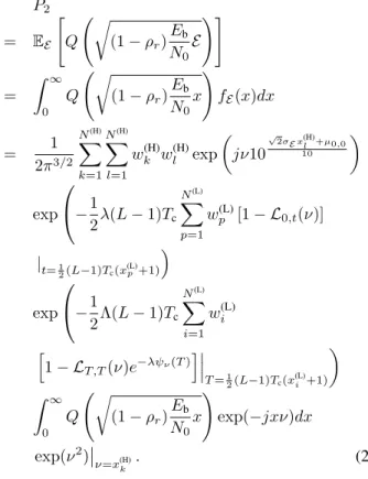
With characteristic function of E, i.e. Ψ(ν) in (12), the PDF of E can be computed by the Gauss-Hermite formula as follows: fE(x) = 1 2π Z ∞ −∞ Ψ(ν)e−jxνdν ≈ 1 2π N(H) X k=1 w(H)k Ψ(ν)e−jxνeν2 ¯ ¯ ¯ ν=x(H) k . (16) Combining (13), (14), (15), and (16), the BER of the RAKE receiver in the IEEE 802.15.3a UWB channel can be computed as P2 = EE " Q Ãr (1 − ρr)Eb N0E !# = Z ∞ 0 Q Ãr (1 − ρr) Eb N0 x ! fE(x)dx = 1 2π3/2 N(H) X k=1 N(H) X l=1 wk(H)w(H)l exp µ jν10 √ 2σE x(H)l +µ0,0 10 ¶ exp −1 2λ(L − 1)Tc N(L) X p=1 w(L) p [1 − L0,t(ν)]| t=1 2(L−1)Tc(x(L)p+1) ´ exp −1 2Λ(L − 1)Tc N(L) X i=1 w(L)i h 1 − LT,T(ν)e−λψν(T ) i¯¯ ¯ T =1 2(L−1)Tc(x(L)i +1) ¶ Z ∞ 0 Q Ãr (1 − ρr)Eb N0 x ! exp(−jxν)dx exp(ν2)¯¯ ν=x(H) k . (17)
Compared to [9], we further consider the impact of parameters
L, Tc, σx2, and the characteristic function of the square of
the path gain into our formula. Also, an explicit computation formula is provided.
IV. NUMERICALRESULTS
A. Simulation Method
In order to check the correctness of the BER formula in the last section, we perform simulation by using MATLAB. We consider the orthogonal binary signal, i.e. the PPM signal. When the information bit is 0, the transmitted signal is
s0(t) =
(
1, 0 ≤ t < Tc,
Here we set Tc = 1 nsec. When the information bit is 1,
the signal waveform is s1(t) = s0(t − δTc), where δ is a
positive integer. From the uwb sv model ct function in [1], we can get the output vectors h and t. The vector t stores the arrival time of every channel impulse response with increasing chronological order. The vector h stores the corresponding amplitude.
We define a template vector p0with size 1×(L+δ), where
the m-th element of p0 (denote by p0[m]) is equal to
p0[m] = P n:t[n]=0h[n], m = 1, P n:(m−2)Tc<t[n]≤(m−1)Tch[n], 2 ≤ m ≤ L, 0, L < m ≤ L + δ. (19) The physical meaning of the vector p0 is the received signal
excluding the noise sampled at a rate of 1/Tcgiven the
infor-mation bit being 0. If the inforinfor-mation bit is 1, then the template vector can be expressed as p1[m] = [01×δ, p0[1], · · · , p0[L]].
After adding noise n, the sampled received signal for information bit 0 becomes r = p0+ [n, 01×δ] and that for
information bit 1 is r = p1+ [01×δ, n]. Note that the noise
vector n contains L independent identically distributed normal random variables, each of which has zero mean and variance of N0/2.
The coherent RAKE receiver is applied to detect the signal in the IEEE 802.15.3a UWB channel. Let the decision variable
U0= r·p0and U1= r·p1, where the operator “·” is the inner
product of two vectors. If U0≥ U1, then the information bit
is 0, otherwise the information bit is 1.
B. Results
Figure 1 compares the BER performance based on (7) in [6] and (17) in our paper. For the BER curve based on [6], we reproduce the curve in [6, Fig. 1], where the received waveform is observed only over a finite window [0, Tmax] and
Tmax= 33 nsec. The symbol η = Ew/(8σ2n), where Ew is the
signal energy of and σ2
n is the noise power spectral density. In
the figure, we observe that the BER based on (17) is slightly higher than that based on (7) of [6]. This is because we take the lognormal shadowing into account.
Figure 2 shows the BER v.s. Eb/N0 for CM1, CM2, CM3,
and CM4 by simulation and analysis. For the analytical curves, We consider the orthogonal binary signal, i.e., ρr = 0. The
parameter δ of the PPM is set to be one. The number of the fingers of the RAKE receiver is 10. The space of the fingers of the RAKE receiver, Tc, is set to 1 nsec. For each given Eb/N0,
we simulate 100,000 bits to obtain the BER. As seen from the figure, the analytical results match the simulation results quite well. However, for CM3 and CM4, there are some differences between the simulation and the analytical curves, which may result from the following reasons:
1) The usage of Gauss-Hermite and Gauss-Legendre for-mulae may cause some error in integrations.
2) We use the MATLAB programs provided in [1] to generate the IEEE 802.15.3a channel. Theoretically the Poisson process has infinite arrivals, but the computer simulation can only generate finite arrivals. The MAT-LAB program in [1] only produces the clusters with the
arrival time up to 10Γ. Meanwhile, each cluster only contains the rays with the arrival time up to 10γ. Thus, the RAKE receiver in the simulation may collect less energy than that in the ideal case. Thus the simulation BER values are slightly higher than the theoretical BER values.
V. CONCLUSIONS
In this work, we have derived the BER analytical formula for receiving the antipodal and orthogonal binary signals by using a coherent RAKE receiver over the IEEE 802.15.3a UWB channel model. Our numerical results show that the simulation and the analytical values of the BER are very close. Using our analytical BER formula can save computer simulation time. Furthermore, the suggested analytical method can be applied to other multipath channel models.
The possible future works that can be extended from this work include the following. First, we plan to analyze the same problem under the IEEE 802.15.4a UWB channel model [10]. Second, we are going to find the ergodic capacity of such a UWB channel models.
APPENDIXI PROOF OFTHEOREM1
Let fG|T,t(x) be the PDF of the path gain G , αk,larriving
at time t that is part of a cluster that started at time T . According to [9], fG|T,t(x) can be written as
fG|T,t(x) = 1
2[f|G||T,t(x) + f|G||T,t(−x)], (20) because the path gain has probability of 1/2 being positive and probability of 1/2 being negative [Recall the definition of path gain in (5) and the following context.] Note that f|G||T,t(x) is
lognormally distributed, i.e.,
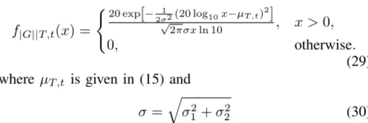
f|G||T,t(x) = (20 exp [− 1 2σ2(20 log10x−µT,t)2] √ 2πσx ln 10 , x > 0, 0, otherwise. (21) where µT,t is given in (1) and σ =
p
σ2
1+ σ22 are the mean
and variance of the random variable 20 log10|G|, respectively.
Note that (1) is the continuous-time representation of (8), because we have changed the discrete indices k and l to continuous arrival time t and T , respectively.
The complete form of the square path gain should be X2G2,
where X is the lognormal shadowing introduced in Section II. Since 20 log10X ∝ Normal(0, σ2
x), we have
20 log10X2= 2(20 log10X) ∝ Normal(0, (2σx)2) (22)
and then 20 log10X2G2 = 2(20 log10X|G|) = 2(20 log10X) + 2(20 log10|G|) ∝ Normal(0, (2σx)2) + Normal(2µT,t, (2σ)2) ∝ Normal(2µT,t, 4(σ12+ σ22+ σ2x)). (23)
Define σE =
p
σ2
1+ σ22+ σx2. Then the PDF of the square of
the path gain arriving at time t that is part of a cluster that started at time T can be written as
fT,t(x) = 10 exp − 1 8σ2E(20 log10x−2µT,t) 2 √ 2πσEx ln 10 , x > 0, 0, otherwise. (24) Denote LT,t(ν) as the characteristic function of fT,t(x), i.e.,
LT,t(ν) = ET,t[ejνX 2G2 ] = Z ∞ −∞ ejνxf T,t(x)dx. (25) Let y = 1
2√2σE(20 log10x − 2µT,t) and apply it to (13). Then
we can have LT,t(ν) = Z ∞ −∞ exp µ jν102 √ 2σE y+2µT,t 20 ¶ 10e−y2 √ 2πσEx ln 10 xσEln 10 5√2 dy = Z ∞ −∞ 1 √ πexp µ jν10 √ 2σE y+µT,t 10 ¶ e−y2dy ≈ N(H) X l=1 w(H)l √1 πexp µ jν10 √ 2σE x(H)l +µT,t 10 ¶ . (26) APPENDIXII PROOF OFTHEOREM2
In [9] the authors have obtained the characteristic function of the sum of path gains in the time window [a, b] (denoted by Φ), but the lognormal shadowing is not taken into account. Similarly, we apply their results to determine the characteristic function of E. Assume that the RAKE receiver with L fingers is used to collect the channel energy in the time window [0, (L − 1)Tc], where Tc is the chip duration between two
fingers.
In [9], the authors defined the following functions:
ψν(T ) = (Rb max(a,T )[1 − LT,t(ν)]dt, T ≤ b, 0, T > b, (27) and J(ν) = Z a 0 [1 − e−λψν(T )]dT + Z b 0 [1 − LT,T(ν)e−λψν(T )]dT. (28) We set a = 0, b = (L − 1)Tc, and use the Gauss-Legendre
formula [11]. Then we can transform the above equations to (14) and (15), respectively.
REFERENCES
[1] J. Foerster, et. al., “Channel modeling sub-committee report final,” IEEE
P802.15 Wireless Personal Area Networks, P802.15-02/490r1-SG3a,
Feb. 2003.
[2] K. Eshima, Y. Hase, S. Oomori, F. Takahashi, and R. Kohno, “M-ary UWB system using Walsh codes,” IEEE Conference on Ultra Wideband
Systems and Technologies, pp. 37–40, May 21–23, 2002.
[3] M. H¨am¨al¨ainen, R. Tesi, and J. Iinatti, “On the UWB system perfor-mance studies in AWGN channel with interference in UMTS band,”
IEEE Conference on Ultra Wideband Systems and Technologies, pp.
321–325, May 21–23, 2002.
[4] ˙I. G¨uvenc¸ and H. Arslan, “Performance evaluation of UWB systems in the presence of timing jitter,” IEEE Conference on Ultra Wideband
Systems and Technologies, pp. 136–141, Nov. 16–19, 2003.
[5] T. Q. S. Quek and M. Z. Win, “Ultrawide bandwidth transmitted-reference signaling,” IEEE International Conference on
Communica-tions, vol. 6, pp. 3409–3413, June 20–24, 2004.
[6] J. A. Gubner and K. Hao, “A computable formula for the average bit-error probability as a function of window size for the IEEE 802.15.3a UWB channel model,” IEEE Trans. Microwave
Theory Tech., submitted for publication. [Online]. Available: http:
//homepages.cae.wisc.edu/∼gubner/GubnerHao MTT UWB.pdf
[7] K. Hao and J. A. Gubner, “Performance measures and statistical quantities of rake receivers using maximal-ratio combining on the IEEE 802.15.3a UWB channel model,” IEEE Trans. Wireless
Commun., submitted for publication. [Online]. Available: http:
//homepages.cae.wisc.edu/∼gubner/HaoGubnerTWaf2col.pdf
[8] J. G. Proakis, Digital Communications, 4th ed. Boston: McGraw-Hill, 2001.
[9] K. Hao and J. A. Gubner, “The distribution of sums of path gains in the IEEE 802.15.3a UWB channel model,” IEEE Trans.
Wireless Commun., submitted for publication. [Online]. Available:
http://homepages.cae.wisc.edu/∼gubner/HaoGubnerTWireless2col.pdf
[10] A. F. Molisch et al., “IEEE 802.15.4a channel model - final report,” IEEE 802.15 WPAN Low Rate Alternative PHY Task Group 4a (TG4a), Tech. Rep., Nov. 2004.
[11] [Online]. Available: http://www.efunda.com/math/num integration/num int gauss.cfm
Fig. 1. BER comparison of the proposed analytical formulae with that in [6], where Tmax= 33 nsec.
Fig. 2. The BER v.s. Eb/N0for the RAKE receiver with 10 fingers in the
1
Performance Analysis of Pulse Based
Ultra-Wideband Systems in the Highly Frequency
Selective Fading Channel with Random Clusters
and Rays
Wei-Cheng Liu and Li-Chun Wang
Department of Communication Engineering
National Chiao Tung University, Hsinchu, Taiwan
[email protected], Tel: +886-3-5712121 ext 54511
Abstract— In this paper, an analytical expression for the bit
error rate (BER) of binary signals in the IEEE 802.15.3a ultra-wideband (UWB) channel is presented. Although the IEEE 802.15.3a channel model is widely adopted, the performance of UWB system in such a channel are mainly evaluated by simulations instead of analysis. The unique characteristics of cluster property and highly dense multipath effect make per-formance analysis in this kind of UWB channel interesting but challenging. Mathematically, the signal in such a UWB channel can be characterized by a joint lognormal and Poisson random signal, where the lognormal random variable models the fading amplitude and the Poisson random variable model the clustering effect. We develop a BER computation method to take into account of all the key parameters in the IEEE 802.15.3a UWB channel, consisting of the cluster/ray arrival rate, cluster/ray decay factor, the number of rays per cluster, lognormal fading and lognormal shadowing. Furthermore, the effect of finger numbers of the RAKE receiver is also considered.
Index Terms— Ultra-wideband (UWB), IEEE 802.15.3a
chan-nel model, bit error rate (BER).
I. INTRODUCTION
U
ULTRA-WIDEBAND (UWB) is a promising technique for wireless communications due to its high speed transmission. However, the UWB channel characteristics are very different from the conventional narrowband channel. Currently, most UWB systems are evaluated by simulations in the complicated channel model or by analysis in a simplified channel model.Thus a fundamental question arises: Can a UWB system be possibly analyzed in a more realistic UWB channel model? The IEEE 802.15.3a UWB channel model [1] is widely adopted for the product development in the industry, while the analysis under such a channel is rarely seen in the literature. This UWB channel has two important properties different from the conventional narrowband channel. First, the extremely highly frequency selective fading occurs in the frequency domain because the UWB signal occurs is much wider than the channel coherence bandwidth. Second, the UWB signals reflected by objects usually yield a number of clusters of rays
1This work was supported by the National Science Council, Taiwan, under
the contract NSC94-2213-E-009-030.
and contain some non-Rayleigh multipath components because the extremely large bandwidth in the time domain leads to the high-resolution arrival time.
A. Problem Statement
The challenges of analyzing such UWB signals can be explained in the following three folds.
• Unlike the narrowband channel model with only one
cluster of fixed-number arrival rays, the transmitted signal over the UWB channel may arrive in many clusters with a random number of arrival rays. Mathematically, the arrival process of the UWB signal can be modeled by a doubly stochastic Poisson process. For a channel with an unknown number of rays, it is difficult to compute how much signal energy is collected at the RAKE receiver.
• The UWB channel presents the characteristics of a
log-normally faded amplitude with a mean related to two Er-lang random variables for varying arrival time of rays and clusters. Signal analysis for such a joint two-dimension random variable is not straightforward.
• Because insufficient arrival rays in a very narrow time bin
cannot justify the assumption of the central limit theorem, the multipath fading signal is not a traditional Rayleigh random variable in the UWB channel. According to measurement results, the IEEE 802.15.3a UWB channel adopts a lognormal multipath fading signal. In addition, shadowing is also considered in the IEEE 802.15.3a chan-nel model. Thus, a UWB signal is a composite slowly varying lognormally shadowed/fast-varying lognormally faded random variable conditioned on the given number of rays and the given signal amplitude’s mean. Again, the analysis of such a signal is rarely seen in the current literature.
In short, a UWB signal in the IEEE 802.15.3a channel model can be characterized by a joint lognormal and dou-bly stochastic Poisson random variable with key parameters including cluster/ray arrival rates, cluster/ray decay factors, and the standard deviations of the lognormal fading and shadowing. To our knowledge, a complete analytical bit error
2
rate (BER) computation formula for the RAKE receiver in the IEEE 802.15.3a UWB channel is not seen in the literature.
B. Related Work
In the following we briefly summarize some published papers in the literature related to the performance analysis of the UWB system under different channels. In [2], the authors derived the theoretical BER of binary and M-ary UWB systems with Walsh codes under the AWGN channel and multiple access interference.
On the one hand, in [3]–[5], the UWB system was inves-tigated in certain simplified UWB channel models. In [3], the authors studied the performances of UWB systems in the AWGN channel in the presence of the interference from the wideband code division multiple access (WCDMA) of the universal mobile telecommunications system (UMTS). The BER performances of the UWB system under the flat and dispersive Rayleigh fading channels with timing jitter were derived in [4]. In [5], based on an approach of defining channel amplitude by a moment generating function, the authors analyze the performance of a transmit-reference (TR) UWB system with a simple autocorrelation receiver under a slow fading channel.
On the other hand, the following papers considered more sophisticated UWB channels [6]–[9]. With respect to the IEEE 802.15.3a channel model, [6] derived a BER formula as a function of the window size. In [7], they further investi-gated the statistics of the output SNR at the RAKE receiver. Reference [8] analyzed how multiple transmit and receive antennas affect the SNR of the UWB signal under a channel characterized by 1) a Gamma distributed path power; 2) a modified Poisson process for modeling the number of the simultaneously arriving paths; 3) an exponentially decayed resolvable path power in the time domain. In [9], the analytical error performance of a multi-antenna with a zero-forcing (ZF) RAKE receiver system over the frequency-selective UWB lognormal fading channels was analyzed.
However, to our knowledge, an explicit BER analytical computation method incorporating the impact of the finger number of the RAKE receiver as well as shadowing effect in the IEEE 802.15.3a UWB channel has not been seen in the literature.
C. Objective and Outline of This Paper
The objective of this paper is to develop an analytical method to compute the BER for the UWB system with a coherent RAKE receiver in a complete IEEE 802.15.3a channel. The difference between [6] and [7] and our work are two folds. First, we consider the lognormal shadowing fading as specified in the IEEE 802.15.3a channel model. Second, we derive an explicit BER formula as a function of the fingers number of the RAKE receiver. The rest of this paper is organized as follows. Section II introduces the IEEE 802.15.3a channel model. In Section III, we derive the expression for evaluating the BER of the binary signals subject to the impact of the considered UWB channel. Section IV shows our numerical results. Last, we give our conclusions in Section V.
II. CHANNELMODEL
In this section, we discuss the key attributes of the IEEE 802.15.3a UWB channel [1]. The impulse response of the considered channel model is
hi(t) = Xi NXc−1 l=0 NXr−1 k=0 αi k,lδ(t − Tli− τk,li ) , (1)
where i refers to the i-th realization, Xi represents the
log-normal shadowing (i.e., 20 log(Xi) ∝ Normal(0, σ2x)), {αik,l}
are the multipath gain coefficients, Ti
l is the delay of the
l-th cluster, τi
k,l is the delay of the k-th multipath component
relative to the l-th cluster arrival time (Ti
l), Nc is the number
of clusters, and Nr is the number of rays for each cluster. By
definition, we have τ0,l = 0.
The distribution of the cluster arrival time and ray arrival time are given by
p(Tl|Tl−1) = ( Λ exp[−Λ(Tl− Tl−1)], Tl> Tl−1, 0, otherwise, (2) for l > 0, and p(τk,l|τ(k−1),l) = ( λ exp[−λ(τk,l− τ(k−1),l)], τk,l> τ(k−1),l, 0, otherwise, (3)
for k > 0, where Λ and λ are the cluster and ray arrival rates, respectively. Note that T0= 0 in the line-of-sight (LOS)
channel. T0is an exponential random variable in the
non-line-of-sight (NLOS) channel, i.e.,
p(T0) =
(
Λ exp(−ΛT0), T0> 0,
0, otherwise. (4)
The channel coefficients (αk,l) are defined as follows:
αk,l= pk,lξlβk,l , (5)
where pk,l is equiprobable ±1 to account for signal inversion
due to reflections, ξl reflects the fading associated with the
l-th cluster, and βk,l corresponds to the fading associated with
the k-th ray of the l-th cluster. The total energy contained in the terms {αk,l} is normalized to unity for each realization.
The distribution of ξlβk,l is
20 log(ξlβk,l) ∝ Normal(µk,l, σ12+ σ22) (6)
or
|ξlβk,l| = 10(µk,l+n1+n2)/20 , (7)
where the two independent normal random variables n1 and
n2 with variance of σ12 and σ22 represent the fading on each
cluster and ray in the dB domain, respectively. Note that
µk,l=10 ln(Ω0) − 10Tl/Γ − 10τk,l/γ ln(10) − (σ2 1+ σ22) ln(10) 20 (8) and E[|ξlβk,l|2] = Ω0e−Tl/Γe−τk,l/γ, (9)
where Ω0is the mean energy in the first path of the first cluster
and Tlis the excess delay of bin l, Γ is the cluster decay factor,
3
Through measurements in [1], some parameters in the IEEE 802.15.3a channel are specified for four different environ-ments, i.e., CM1, CM2, CM3, and CM4 for LOS (0-4 m), NLOS (0-4 m), NLOS (4-10 m), and extreme NLOS multipath channel with 25 nsec rms delay spread, respectively.
III. BER ANALYSIS
A. Receiver Structure
For a coherent RAKE receiver with L fingers, the received SNR γb is γb= Eb N0 L X k=1 a2k= L X k=1 γk , (10)
where Eb/N0 is the bit SNR, ak is the channel amplitude at
the k-th finger of the RAKE receiver. From [10] we know that the conditional error probability for binary signals for the coherent RAKE receiver is
P2(γb) = Q
³p
γb(1 − ρr)
´
, (11) where ρr = −1 for antipodal signals and ρr = 0 for
orthogonal signals. Denote E ,PLk=1a2
k the received energy
in the UWB channel.
B. Characteristic Function of the Received Energy (E)
Here we derive the characteristic function of E. We extend the results in [11] to further take into account of the finger numbers of the RAKE receiver (L), the chip duration (Tc), and
shadowing. Instead of estimating the path gain, we directly calculate the square of a path gain in the UWB channel to facilitate the BER evaluation of the RAKE receiver in the UWB channel.
Corollary 1: The received energy E has the following
prop-erties: E can be written as the sum of three statistically independent terms
E = X2α2
0,0+ Φr0+ Φ⊗ , (12)
where X and α0,0 are defined in (1), Φr0 is the energy of the
first cluster excluding the first ray, Φ⊗ is the total energy of
the remaining clusters. Then, the characteristic function of the received energy (E) in the IEEE 802.15.3a UWB channel is
Ψ(ν) = L0,0(ν)R(ν)S(ν), (13)
where LT,t(ν) is the characteristic function of the single path
squared gain in the IEEE 802.15.3a UWB channel with the cluster arriving at time T and the ray arriving at T + τ , R(ν) and S(ν) are the characteristic functions of Φr0 and Φ⊗,
respectively.
Proof: See [11].
Compared to [11], we further consider the impact of param-eters L, Tc, σx2, and the characteristic function of the square
of the path gain into LT,t(ν), R(ν), and S(ν). Also, explicit
computation formulas are provided.
Theorem 1: Consider a RAKE receiver with L fingers in
the IEEE 802.15.3a UWB channel. The characteristic function
LT,t(ν) can be computed by LT,t(ν) = Z ∞ 0 ejνx10 exp h − 1 8σ2 E (20 log10x − 2µT,t) 2i √ 2πσEx ln 10 dx ≈ N(H) X l=1 wl(H)√1 πexp µ jν10 √ 2σE x(H)l +µT,t 10 ¶ (14) where µT,t= 10 ln 10 " ln Ω0−T Γ − t − T γ − µ ln 10 10 ¶2 σ2 E 2 # (15) and σE = q σ2 1+ σ22+ σx2 . (16)
The parameters Ω0, Γ, and γ are defined in (9). Note that σE
consists of σ1, σ2, and σx, which represent the standard
devi-ation of cluster fading, ray fading, and lognormal shadowing fading terms, respectively. {wl(H)} and {x(H)l } are the weights
and abscissas of the Gauss-Hermite formula [12], respectively.
N(H)is the number of points of the Gauss-Hermite integration.
Proof: See Appendix I.
Theorem 2: For the RAKE receiver with L fingers, the
function R(ν) in (13) can be written in the form of
R(ν) = e−λψν(0) , (17)
where the function ψν(T ) can be computed by
ψν(T ) = (R(L−1)Tc T [1 − LT,t(ν)]dt, T ≤ (L − 1)Tc, 0, T > (L − 1)Tc, ≈ (L−1)Tc−T 2 PN(L) p=1w(L)p [1 − LT,t(ν)] |t=(L−1)Tc−T 2 x (L) p+(L−1)Tc+T2 , T ≤ (L − 1)Tc, 0, T > (L − 1)Tc, (18)
where Tcis the chip duration between two fingers, {w(L)p } and
{x(L)
p } are the weights and abscissas of the Gauss-Legendre
formula [12], respectively. N(L) is the number of points of the
Gauss-Legendre integration. Similarly, we can prove that S(ν) can be written in the form of
S(ν) = e−ΛJ(ν) , (19) where the function J(ν) can be computed by
J(ν) = Z (L−1)Tc 0 [1 − LT,T(ν)e−λψν(T )]dT ≈ (L − 1)Tc 2 N(L) X i=1 wi(L) h 1 − LT,T(ν)e−λψν(T ) i |T =(L−1)Tc 2 x(L)i +(L−1)Tc2 . (20)
4
With the characteristic function Ψ(ν) of E, the PDF of E can be computed by the Gauss-Hermite formula as follows:
fE(x) = 1 2π Z ∞ −∞ Ψ(ν)e−jxνdν ≈ 1 2π N(H) X k=1 w(H)k Ψ(ν)e−jxνeν2 ¯ ¯ ¯ ν=x(H)k . (21)
Combining (14), (18), (20), and (21), the BER of the RAKE receiver in the IEEE 802.15.3a UWB channel can be computed as P2 = EE " Q Ãr (1 − ρr)Eb N0 E !# = Z ∞ 0 Q Ãr (1 − ρr)Eb N0x ! fE(x)dx = 1 2π3/2 N(H) X k=1 N(H) X l=1 wk(H)w(H)l exp µ jν10 √ 2σE x(H)l +µ0,0 10 ¶ exp −1 2λ(L − 1)Tc N(L) X p=1 w(L) p [1 − L0,t(ν)] |t=1 2(L−1)Tc(x(L)p+1) ´ exp −1 2Λ(L − 1)Tc N(L) X i=1 wi(L) h 1 − LT,T(ν)e−λψν(T ) i¯¯ ¯ T =1 2(L−1)Tc(x(L)i +1) ¶ Z ∞ 0 Q Ãr (1 − ρr)Eb N0x ! exp(−jxν)dx exp(ν2)¯¯ ν=x(H) k . (22)
IV. NUMERICALRESULTS
A. Simulation Method
In order to check the correctness of the BER formula in the last section, we perform simulation by MATLAB. We consider the orthogonal binary signal, i.e., the pulse position modulation (PPM) signal. When the information bit is 0, the transmitted signal is
s0(t) =
(
1, 0 ≤ t < Tc,
0, otherwise. (23)
Here we set Tc= 1 nsec. When the information bit is 1, the
signal waveform is s1(t) = s0(t − δTc), where δ is a positive
integer. From the uwb sv model ct function in [1], we can get the output vectors h and t. The vector t stores the arrival time of every channel impulse response with increasingly chronological order. The vector h stores the corresponding amplitude.
We define a template vector p0with size 1×(L+δ), where
the m-th element of p0 (denoted by p0[m]) is equal to
p0[m] = P n:t[n]=0h[n], m = 1, P n:(m−2)Tc<t[n]≤(m−1)Tch[n], 2 ≤ m ≤ L, 0, L < m ≤ L + δ. (24) The physical meaning of vector p0 is the received signal
ex-cluding the noise sampled at a rate of 1/Tcfor the information
bit 0. If the information bit is 1, then the template vector can be expressed as
p1= [01×δ, p0[1], · · · , p0[L]] (25)
After adding noise n, the sampled received signal for information bit 0 becomes
r = p0+ [n, 01×δ], (26)
and that for information bit 1 is
r = p1+ [01×δ, n]. (27)
Note that the noise vector n contains L independent identically distributed normal random variables, each of which has zero mean and variance of N0/2.
The coherent RAKE receiver is applied to detect the signal in the IEEE 802.15.3a UWB channel. Let the decision variable
U0= r·p0and U1= r·p1, where the operator “·” is the inner
product of two vectors. If U0 ≥ U1, then the information bit
is 0; otherwise, the information bit is 1.
B. Results
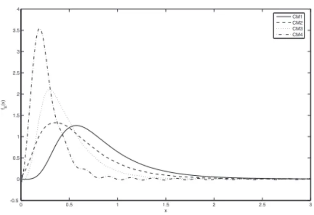
Figure 1 shows the PDF fE(x) for CM1, CM2, CM3, and
CM4 according to (21). The number of fingers of the RAKE receiver is 10. CM1 has most probability mass in the high energy range; CM2 ranks second; CM3 ranks third; and CM4 has least probability mass in the range of higher energy range. This phenomenon can explain why CM1 has the best BER performance compared to CM2, CM3, and CM4.
Figure 2 shows the PDF fE(x) for various numbers of
RAKE fingers L = 20, 30, 40, and 50 in the channel model CM1. The PDFs of L = 30, 40, and 50 are about the same, while the probability mass of L = 20 is in the lower energy range.
Figure 3 compares the BER performance based on (7) in [6] and (22) in our paper. For the BER curve based on [6], we reproduce the curve in [6, Fig. 1], where the received waveform is observed only over a finite window [0, Tmax] with
Tmax= 33 nsec. The symbol η = Ew/(8σn2), where Ewis the
signal energy and σ2
n is the noise power spectral density. In
the figure, we observe that the BER obtained from (22) is slightly higher than that obtained from (7) of [6] because of the lognormal shadowing.
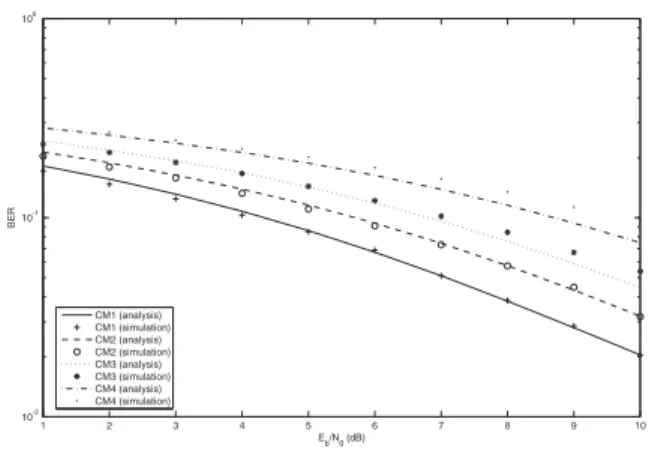
Figure 4 shows the BER v.s. Eb/N0for CM1, CM2, CM3,
and CM4 by simulation and analysis for ρr = 0, i.e., the
orthogonal binary signal. The parameter δ of the PPM is set to one, the number of the fingers of the RAKE receiver is 10, and Tc is 1 nsec. For a given Eb/N0, we simulate 100,000
5
results match the simulation results quite well. However, there are some differences between the simulation and the analytical curves for CM3 and CM4. We explain reasons as follows:
1) The usage of Gauss-Hermite and Gauss-Legendre for-mulas may cause some error in integrations.
2) We use the MATLAB programs provided in [1] to generate the IEEE 802.15.3a channel. Theoretically, the Poisson process has infinite arrivals, but the computer simulation can only generate finite arrivals. The MAT-LAB program in [1] only produces the clusters with the arrival time up to 10Γ. Meanwhile, each cluster only contains the rays with the arrival time up to 10γ. Thus, the RAKE receiver in the simulation may collect less energy than that in the ideal case. Thus the simulation BER values are slightly higher than the theoretical BER values.
Figure 5 shows the BER v.s. the number of fingers of the RAKE receiver for CM1, CM2, CM3, and CM4 at Eb/N0=
5 dB. The other parameters are the same as those of the simulation in Fig. 4. As L increases, the BER decreases because of collecting more energy. For a large value of L, the BER curves become flat because the RAKE receiver almost captures all the channel energy. In the figure we can see that the BERs of CM1, CM2, and CM3 converge to a common value when L = 50 except for CM4. Note that CM4 has the largest delay spread. Thus, a portion of the energy in the region of L > 50 is not received, thereby resulting in higher BER than CM1, CM2, and CM3.
V. CONCLUSIONS
In this work, we have derived the BER analytical formula for the antipodal and orthogonal binary signals with a co-herent RAKE receiver in the IEEE 802.15.3a UWB channel model. Our numerical results show that the simulation and the analytical values of the BER are very close. The analytical BER formula can significantly save computer simulation time. Furthermore, the suggested analytical method can be applied to other multipath channel models with random numbers of clusters and rays.
The possible future works that can be extended from this work include the following. First, we plan to analyze the same problem under the IEEE 802.15.4a UWB channel model [13]. Second, we are going to find the ergodic capacity of such a UWB channel models.
APPENDIXI
PROOF OFTHEOREM1
Let fG|T,t(x) be the PDF of the path gain G , αk,larriving
at time t that is part of a cluster that started at time T . According to [11], fG|T,t(x) can be written as
fG|T,t(x) =
1
2[f|G||T,t(x) + f|G||T,t(−x)], (28) because the path gain is positive or negative with equal probability of 0.5. [Recall the definition of path gain in (5)
and the following context.] Note that f|G||T,t(x) is lognormally
distributed, i.e., f|G||T,t(x) = (20 exp[− 1 2σ2(20 log10x−µT,t) 2] √ 2πσx ln 10 , x > 0, 0, otherwise. (29) where µT,t is given in (15) and
σ =
q
σ2
1+ σ22 (30)
are the mean and variance of the random variable 20 log10|G|,
respectively. Note that (15) is the continuous-time representa-tion of (8) because the discrete indices k and l are changed to continuous arrival time t and T , respectively.
The complete form of the square path gain should be X2G2,
where X is the lognormal shadowing introduced in Section II. Since 20 log10X ∝ Normal(0, σ2x), we have
20 log10X2= 2(20 log10X) ∝ Normal(0, (2σx)2) . (31)
Then, it follows that
20 log10X2G2 = 2(20 log 10X|G|) = 2(20 log10X) + 2(20 log10|G|) ∝ Normal(0, (2σx)2) + Normal(2µT,t, (2σ)2) ∝ Normal(2µT,t, 4(σ12+ σ22+ σx2)) . (32) Define σE = p σ2
1+ σ22+ σ2x. Then the PDF of the square of
the path gain arriving at time t in a cluster starting at time T can be written as fT,t(x) = 10 exp − 1 8σ2E(20 log10x−2µT,t) 2 √ 2πσEx ln 10 , x > 0, 0, otherwise. (33) Denote LT,t(ν) as the characteristic function of fT,t(x), i.e.,
LT,t(ν) = ET,t[ejνX 2G2 ] = Z ∞ −∞ ejνxf T,t(x)dx. (34) Let y = 1
2√2σE(20 log10x − 2µT,t) in (14). Then we can have
LT,t(ν) = Z ∞ −∞ exp µ jν102 √ 2σE y+2µT,t 20 ¶ 10e−y2 √ 2πσEx ln 10 xσEln 10 5√2 dy = Z ∞ −∞ 1 √ πexp µ jν10 √ 2σE y+µT,t 10 ¶ e−y2 dy ≈ N(H) X l=1 wl(H)√1 πexp µ jν10 √ 2σE x(H)l +µT,t 10 ¶ . (35) APPENDIXII PROOF OFTHEOREM2
In [11] the authors have obtained the characteristic function of the sum of path gains in the time window [a, b] (denoted by Φ), but the lognormal shadowing is not taken into account. Similarly, we apply their results to determine the characteristic function of E. Assume that the RAKE receiver with L fingers is used to collect the channel energy in the time window [0, (L − 1)Tc], where Tc is the chip duration between two
6
In [11], the authors defined the following functions:
ψν(T ) = (Rb max(a,T )[1 − LT,t(ν)]dt, T ≤ b, 0, T > b, (36) and J(ν) = Z a 0 [1 − e−λψν(T )]dT + Z b a [1 − LT,T(ν)e−λψν(T )]dT. (37) We set a = 0, b = (L − 1)Tc and use the Gauss-Legendre
formula. Then we can transform the above equations to (18) and (20), respectively.
REFERENCES
[1] J. Foerster, et. al., “Channel modeling sub-committee report final,” IEEE
P802.15 Wireless Personal Area Networks, P802.15-02/490r1-SG3a,
Feb. 2003.
[2] K. Eshima, Y. Hase, S. Oomori, F. Takahashi, and R. Kohno, “M-ary UWB system using Walsh codes,” IEEE Conference on Ultra Wideband
Systems and Technologies, pp. 37–40, May 21–23, 2002.
[3] M. H¨am¨al¨ainen, R. Tesi, and J. Iinatti, “On the UWB system perfor-mance studies in AWGN channel with interference in UMTS band,”
IEEE Conference on Ultra Wideband Systems and Technologies, pp.
321–325, May 21–23, 2002.
[4] ˙I. G¨uvenc¸ and H. Arslan, “Performance evaluation of UWB systems in the presence of timing jitter,” IEEE Conference on Ultra Wideband
Systems and Technologies, pp. 136–141, Nov. 16–19, 2003.
[5] T. Q. S. Quek and M. Z. Win, “Ultrawide bandwidth transmitted-reference signaling,” IEEE International Conference on
Communica-tions, vol. 6, pp. 3409–3413, June 20–24, 2004.
[6] J. A. Gubner and K. Hao, “A computable formula for the average bit-error probability as a function of window size for the IEEE 802.15.3a UWB channel model,” IEEE Trans. Microwave
Theory Tech., submitted for publication. [Online]. Available: http:
//homepages.cae.wisc.edu/∼gubner/GubnerHao MTT UWB.pdf
[7] K. Hao and J. A. Gubner, “Performance measures and statistical quantities of rake receivers using maximal-ratio combining on the IEEE 802.15.3a UWB channel model,” IEEE Trans. Wireless
Commun., submitted for publication. [Online]. Available: http:
//homepages.cae.wisc.edu/∼gubner/HaoGubnerTWaf2col.pdf
[8] L.-C. Wang, W.-C. Liu, and K.-J. Shieh, “On the performance of using multiple transmit and receive antennas in pulse-based ultrawideband systems,” IEEE Trans. Wireless Commun., vol. 4, no. 6, pp. 2738–2750, Nov. 2005.
[9] H. Liu, R. C. Qiu, and Z. Tian, “Error performance of pulse-based ultra-wideband MIMO systems over indoor wireless channels,” IEEE Trans.
Wireless Commun., vol. 4, no. 6, pp. 2939–2944, Nov. 2005.
[10] J. G. Proakis, Digital Communications, 4th ed. Boston: McGraw-Hill, 2001.
[11] K. Hao and J. A. Gubner, “The distribution of sums of path gains in the IEEE 802.15.3a UWB channel model,” IEEE Trans.
Wireless Commun., submitted for publication. [Online]. Available:
http://homepages.cae.wisc.edu/∼gubner/HaoGubnerTWireless2col.pdf
[12] [Online]. Available: http://www.efunda.com/math/num integration/num int gauss.cfm
[13] A. F. Molisch et al., “IEEE 802.15.4a channel model - final report,” IEEE 802.15 WPAN Low Rate Alternative PHY Task Group 4a (TG4a), Tech. Rep., Nov. 2004.
Fig. 1. The PDF fE(x) for a RAKE receiver with 10 fingers in the IEEE
802.15.3a UWB channels CM1, CM2, CM3, and CM4.
Fig. 2. The PDF fE(x) of a RAKE receiver with finger number L =
20, 30, 40, and 50 in the IEEE 802.15.3a UWB channel CM1.
Fig. 3. BER comparison of the proposed analytical formulas with that in [6], where Tmax= 33 nsec.
7
Fig. 4. The BER v.s. Eb/N0for the RAKE receiver with 10 fingers in the
IEEE 802.15.3a UWB channels CM1, CM2, CM3, and CM4.
Fig. 5. The BER v.s. the number of fingers of the RAKE receiver (L) for CM1, CM2, CM3, and CM4, where Eb/N0= 5 dB.
1
BER Analysis of the IEEE 802.15.4a Channel
Model with RAKE Receiver
Wei-Cheng Liu and Li-Chun Wang
Department of Communication Engineering
National Chiao Tung University, Hsinchu, Taiwan
[email protected], Tel: +886-3-5712121 ext 54511
Abstract— This paper provides the bit error rate (BER)
anal-ysis of the antipodal and orthogonal binary signals under the ultra-wideband (UWB) channel. We offer an analytical expression and its evaluation formula for the BER. The channel model we consider is the IEEE 802.15.4a UWB channel. We take into account of the impact of all the key parameters, including inter-cluster arrival rate, inter-cluster decay constant, the inter-ray arrival rate, ray decay constant, parameters of the power delay profile (PDP), and the distribution of a Nakagami fading signal. For the IEEE 802.15.4a UWB channel, the effects of clustering are characterized by a Poisson process, and the inter-ray arrival time is modeled as the hyperexponential random variable. We propose a systematic analytical method to evaluate the BER performance of the UWB signal associated with such joint continuous Nakagami and discrete Poisson random variable. Thus, the developed analytical model is useful in evaluating the performance of an UWB signal in the IEEE 802.15.4a channel without time consuming simulations.
Index Terms— Ultra-wideband (UWB), IEEE 802.15.4a
chan-nel model, bit error rate (BER).
I. INTRODUCTION
T
HE trend of the modern wireless systems is to achievehigher data rates and better quality. The ultra-wideband (UWB) communications is a possible technique to achieve this objective, due to its extremely large bandwidth. Performance analysis, such as bit error rate (BER) analysis, of the UWB communication system in a realistic UWB channel is impor-tant but a difficult task.
In this work, we use the IEEE 802.15.4a UWB channel model [1] as our channel model, which is based on the recent measurements and close to the realistic UWB channel. The UWB channel has two important properties that is different from the traditional narrow band channel: 1) The bandwidth of the UWB signals is much larger than the coherence bandwidth of the channel. Thus, in the frequency domain, the severely highly frequency selective fading occurs. 2) The large bandwidth results in high resolution arrival time for the UWB signal. Thus, the reflected UWB waves by objects arrive in many clusters, which may contain some non-Rayleigh multipath components.
A. Motivation
The difficulties of analyzing UWB signals can be discussed in three aspects.
1This work is supported by the National Science Council, Taiwan, under
the contract NSC94-2213-E-009-030.
• First, the narrow band channel model does not have the
concept of cluster. The number of the channel impulse response is a fixed constant. On the contrary, the trans-mitted signal over the UWB channel may arrive in many clusters, of which the number of arrival rays is random. The number of the clusters is also random, which is modeled as the Poisson random variable. Mathematically, the interarrival time of the rays within a cluster is the hyperexponential random variable. The collected signal energy at the RAKE receiver in a channel with random number of clusters and rays is difficult to analyze.
• The amplitude of the impulse response in the UWB
chan-nel is a multidimensional random variable, consisting of the Nakagami m faded amplitude with a mean related to an exponential and a hyperexponential random variable. This is because the average of the channel impulse is also a random variable due to varying interarrival time of rays and clusters. The parameter m of the Nakagami random variable is a lognormal random variable, of which the mean and the standard deviation are both dependent on the arrival time of the rays.
• The number of arrival rays in a very narrow time bin (or
chip duration) is not very large, so the central limit the-orem is no longer applicable here. Thus, the distribution of fading is not a traditional Rayleigh random variable as in the narrow band case. In the IEEE 802.15.4a UWB channel, the multipath fading signal is characterized by a Nakagami m random variable according to measurement results. Thus, for a given number of rays and the mean of the signal amplitude, a UWB signal is a fast-varying Nakagami m faded random variable. The analysis of such a signal is rarely seen in current literature.
The IEEE 802.15.4a UWB channel model defines nine sets of parameters for different environments. Based on this channel model, a UWB signal can be characterized by a joint continuous Nakagami m, a discrete Poisson random variable for clusters, and a discrete counting random variable with interarrival time being hyperexponential distributed, of which key parameters include the inter-cluster arrival rate, ray arrival rates (mixed Poisson model parameters), inter-cluster decay constant, intra-cluster decay time constant parameters, Nak-agami m factor mean, NakNak-agami m factor variance, NakNak-agami
m factor for strong components, and parameters for alternative
![Fig. 1. BER comparison of the proposed analytical formulae with that in [6], where T max = 33 nsec.](https://thumb-ap.123doks.com/thumbv2/9libinfo/8736874.203346/9.918.80.494.108.553/fig-ber-comparison-proposed-analytical-formulae-max-nsec.webp)