國
立
交
通
大
學
網路工程研究所
碩 士 論 文
都會區車載隨意網路下基於紅綠燈之可靠繞徑技術
A Traffic Light Based Reliable Routing Protocol for Urban VANETs
研 究 生:張景喬
ii
都會區車載隨意網路下基於紅綠燈之可靠繞徑技術
A Traffic Light Based Reliable Routing Protocol for Urban VANETs
研 究 生:張景喬 Student:Ching-Chiao Chang
指導教授:王國禎 Advisor:Kuochen Wang
國 立 交 通 大 學
網 路 工 程 研 究 所
碩 士 論 文
A ThesisSubmitted to Institute of Computer Science and Engineering Department of Computer Science
National Chiao Tung University in Partial Fulfillment of the Requirements
for the Degree of Master
in
Computer Science
June 2012
Hsinchu, Taiwan, Republic of China
都會區車載隨意網路下基於紅綠燈之可靠繞徑技術
學生:張景喬 指導教授:王國禎 教授
國立交通大學 網路工程研究所
摘 要
在本篇論文中,我們簡明的介紹和分析車載隨意網路(VANETs)和行動隨
意網路(MANETs)之差別,並且討論車載隨意網路的挑戰。我們比較了現有
車載隨意網路的繞俓協定,發現封包傳輸率和端至端延遲時間仍有改善空
間。由於車載網路中的車輛在道路上高速移動的特性,如何在車載網路的
環境中提供穩定的車輛間資料封包傳輸成了一個很大的挑戰。當我們在討
論車載隨意網路的資料封包傳輸時,繞徑協定是一個重要的議題。因此,
我們提出了一個基於紅綠燈的可靠遶徑技術(TLR),它利用十字路口作為資
料傳遞的基礎,並善用紅綠燈前車輛等候紅燈的特性來提升封包傳輸率。
iv
提升了CLA及RBVT-P十個百分比和二十個百分比的封包傳輸率,以及減少20
毫秒和80毫秒的端至端延遲時間。比起TLR,雖然RBVT-R有好的封包傳輸率,
但是其端至端延遲時間非常的高。
A Traffic Light Based Reliable Routing
Protocol for Urban VANETs
Student: Ching-Chiao Chang Advisor: Dr. Kuochen Wang
Department of Computer Science National Chiao Tung University
Abstract
In this paper, we briefly introduce and analyze differences between vehicular ad hoc networks (VANETs) and mobile ad hoc networks (MANETs), and discuss some challenges of VANETs. Then, we compare existing routing protocols over VANETs to find ways to further improve the packet delivery ratio and end-to-end delay. Due to the high mobility feature of VANETs, the inter-vehicle communication is a big challenge. Routing is a crucial issue when we discuss about data packet transmissions among vehicles. In the proposed reliable routing protocol, traffic light based routing (TLR), we used road intersections as the basis for data forwarding and leverage vehicles waiting at red traffic lights to improve the packet delivery ratio. We also discussed how to compute the backoff delay for reducing collisions when nodes receive data packets in selected virtual cells. In urban areas, traffic lights are located at road
vi
Acknowledgements
Many people have helped me with this thesis. I am in debt of gratitude to my thesis advisor, Dr. Kuochen Wang, for his intensive advice and guidance. I would also like to show my appreciation for all the classmates in the Mobile Computing and Broadband Networking
Laboratory for their invaluable assistance and inspirations. The supports by National Science
Council under Grants NSC 99-2221-E-009-081-MY3, NSC 100-2219-E-009-004 and NSC 101-2219-E-009-001 are gratefully acknowledged. Finally, I thank my father, my mother, my siblings and my friends for their endless love and support.
viii
Contents
摘 要 ... iii Abstract ... v Contents ... viii List of Figures ... x List of Tables ... xi Chapter 1 Introduction ... 1 1.1 Motivation ... 1 1.2 Research objective ... 2 1.3 Thesis organization ... 2 Chapter 2 Background ... 32.1 Node-centric routing protocols ... 3
2.2 Proactive protocols and reactive protocols ... 4
Chapter 3 Related Work ... 5
3.1 Connectionless approach (CLA) [10] ... 5
3.2 Road-based routing using real-time vehicular traffic (RBVT) [12] ... 6
3.3 Parked Vehicle Assistance (PVA) [17]... 7
3.4 Comparison of different routing protocols ... 7
Chapter 4 Proposed Traffic Light Based Routing ... 9
4.1 Virtual cell IDs ... 9
4.3 Route discovery ... 11
4.4 Data forwarding ... 12
4.5 Backoff delay computation ... 14
4.6 An example of data forwarding ... 15
Chapter 5 Simulation and Discussion ... 16
5.1 Simulation setup ... 16
5.2 Simulation results and discussion ... 18
Chapter 6 Conclusion ... 22
6.1 Concluding remarks ... 22
6.2 Future work ... 22
x
List of Figures
Figure 1. Virtual cell of CLA. ... 6
Figure 2. An example of specifying virtual cell IDs on road intersections. ... 10
Figure 3. A road map is divided into virtual cells and a traffic light cell is included in a virtual cell. ... 11
Figure 4. Flowchart of a node forwarding a data packet from source to destination nodes. .... 13
Figure 5. An example of data forwarding... 15
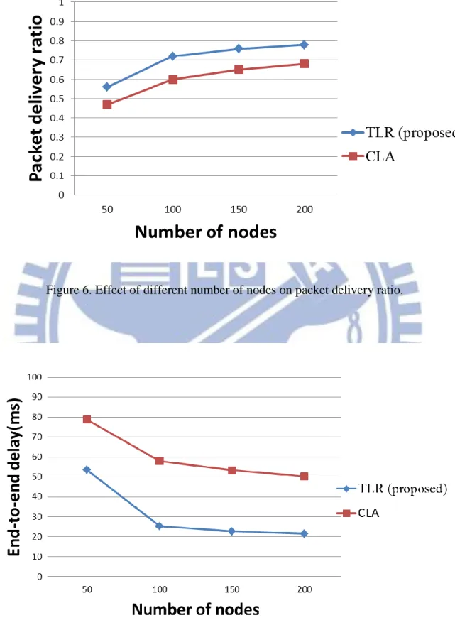
Figure 6. Effect of different number of nodes on packet delivery ratio. ... 19
Figure 7. Effect of different number of nodes on end-to-end delay. ... 19
Figure 8. Effect of different number of nodes on control overhead. ... 20
Figure 9. Effect of different packet rate on packet delivery ratio... 21
List of Tables
Table 1. Comparison of MANETs and VANETs [1] ... 1
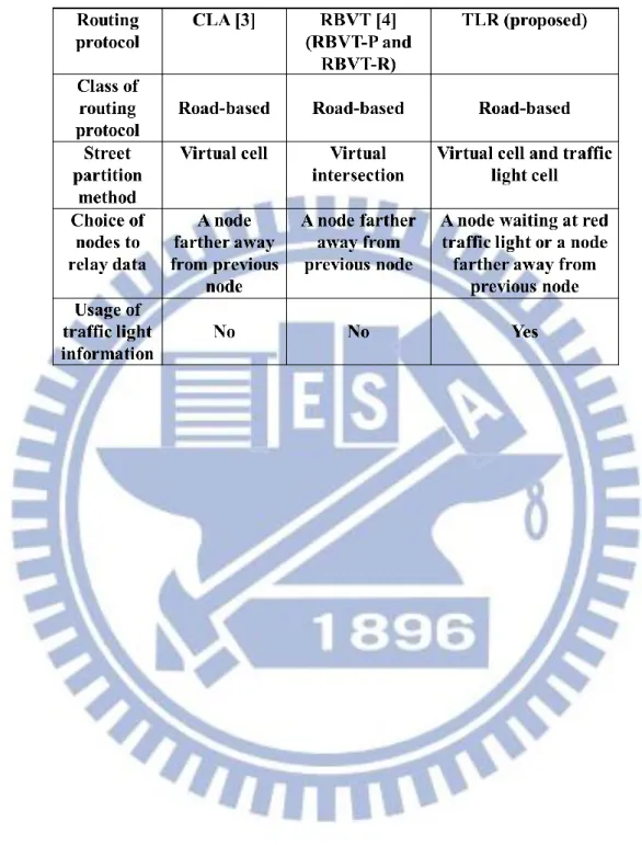
Table 2. Comparison of different road-based routing protocols ... 8
Table 3. Simulation settings for GlomoSim [16]. ... 17
1
Chapter 1
Introduction
Recently, Vehicle Ad Hoc Networks (VANETs) have become a popular research topic. Mobile Ad Hoc Networks (MANETs) have been studied for decades. With specific requirements, VANETs are a specialized form of MANETs. However, there are some differences between VANETs and MANETs. Firstly, as shown in Table 1, the moving pattern of a node is restricted to the roads for VANETs, but the moving pattern of a node is random for MANETs. Secondly, much better hardware (i.e., better CPU, bigger memory, bigger batteries and so on) can be added to a node for VANETs than a node for MANETs. Thirdly, the mobility of a node for VANETs is around five to eight times faster than a node for MANETs [1]. Due to these differences, VANET research has become an active research.
Table 1. Comparison of MANETs and VANETs [1]
1.1 Motivation
VANET applications bring a lot of convenience to our life, such as highway safety, commercial advertisement, and digital entertainment. However, transferring data packets in urban VANETs has many challenges. VANETs are high mobility wireless ad hoc networks. Their topologies are changed frequently which may cause several problems, such as broken
MANET VANET
Low High
Slow Fast
Easy Hard
High Low
Random Restricted to the roads Up to 100 m Up to 1000 m Radio transmission range
Mobility Change in topology
Comparison of MANETs and VANETs Ad hoc network
Maintainance of connections between nodes Resource limited on nodes
links, decrease of packet delivery ratio, and increase of end-to-end delay. Traditional node-centric routing protocols (i.e., ad hoc on-demand distance vector (AODV) and dynamic source routing (DSR)) may lead to unstable frequent broken routes in high mobility urban VANET environments. In order to resolve these problems, we propose a more reliable road-based routing protocol for urban VANETs.
1.2 Research objective
In this paper, a traffic light based routing protocol is proposed and it focuses onestablishing road-based routing paths by using vehicles in traffic light cells located at road intersections. Vehicles stay in traffic light cells due to red lights usually have zero or low mobility. We utilize this characteristic of zero or low mobility to enhance the packet delivery ratio and decrease the end-to-end delay to make inter-vehicle data transmissions more reliable.
1.3 Thesis organization
The rest of this thesis is organized as follows. Chapter 2 describes the background. Chapter 3 presents the related work. In Chapter 4, we detail our TLR protocol. Simulation results are discussed in Chapter 5. In Chapter 6, we give concluding remarks and outline future work.
3
Chapter 2
Background
In VANETs, due to the highly mobility situation, finding stable routes is a big challenge. The following section first describes node-centric routing protocols. Then proactive and reactive routing protocols are reviewed. The road-based routing protocol will be described in Chapter 3.
2.1 Node-centric routing protocols
In node-centric routing protocols, such as DSR [3] and AODV [2], each node has its own routing table which records the information of the node, such as source node ID, destination node ID and relay node IDs. Each node knows the location of all other nodes. For DSR, once a node receives an ROUTE REQUEST (RREQ) packet, if the node has not seen it before, it adds its node ID to the route and forwards the RREQ to its neighbors. If there is any broken link due to the network topology changes, the source node can issue another RREQ to find a new route [15]. For AODV, the source node broadcasts an RREQ packet until the packets reach to the destination node or an intermediate node containing the routes to the destination node. In either case, the node replies back an RREP packet to the source node along the route taken by RREQ. When a broken link is detected, an ROUTE ERROR packet will be sent to the source node by a node recently using this broken link. Then the source node issues new route discovery [15]. However, high velocity nodes result in very short window of communication between nodes on different streets [10]. The built route expires quickly and the source node needs to re-issue new route discovery after sending only few data. When
applied to urban VANET environments, these protocols cause high control overhead in terms of RREQ and RREP packets.
2.2 Proactive protocols and reactive protocols
Routing protocols can be divided into two basic types: proactive protocols and reactive protocols. Proactive protocols (table-driven), such as FSR [5], DSDV [6], OLSR [7], need to maintain routing tables, by sending periodic control packets, such as RREQ and RREP packets. The main disadvantage of this type of protocols is that it needs to maintain routing tables by periodically sending RREQ packets and RREP packets. That is is has high control overhead. In reactive routing protocols, such as AODV [2] and DSR [3], when there are data packets need to be sent, this type of protocols sends RREQ and RREP packets to construct routes. The main disadvantage is the end-to-end delay needed to construct new routes.
5
Chapter 3
Related Work
Our routing protocol is a road-based routing protocol. In sections 3.1 and 3.2, two road-based routing protocols are reviewed. In section 3.3, a routing protocol using parked vehicles is reviewed. Its idea of using stationary vehicles for packet forwarding can support our approach of using vehicles stopping at the red traffic lights for data forwarding. In section 3.4, different routing protocols are compared.
3.1 Connectionless approach (CLA)
[10]
The connectionless approach (CLA) is a road-based routing protocol [10]. It can adapt to the change of the network topology rapidly. This protocol does not need to build a routing table to maintain the positions of neighbor nodes, and it does not need to maintain a hop-by-hop route between the source and destination nodes. The nodes belong to the selected cells in the virtual cell list can receive or forward data. When a relay node leaves the selected cell, it is no need to relay data.
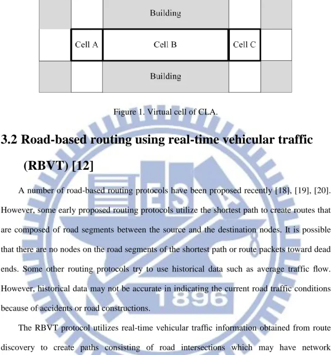
However, as shown in Figure 1, cell A and cell C are located in road intersections where nodes would have short time to relay data packets. A relay node in such a cell would not relay data long enough, so a different node needs to be found frequently to relay data. Another disadvantage of this approach is that, in a selected cell, a high speed node may be chosen, which also have short time to relay data packets in the cell if we do not set high backoff delays to nodes with high speeds.
Figure 1. Virtual cell of CLA.
3.2 Road-based routing using real-time vehicular traffic
(RBVT) [12]
A number of road-based routing protocols have been proposed recently [18], [19], [20]. However, some early proposed routing protocols utilize the shortest path to create routes that are composed of road segments between the source and the destination nodes. It is possible that there are no nodes on the road segments of the shortest path or route packets toward dead ends. Some other routing protocols try to use historical data such as average traffic flow. However, historical data may not be accurate in indicating the current road traffic conditions because of accidents or road constructions.
The RBVT protocol utilizes real-time vehicular traffic information obtained from route discovery to create paths consisting of road intersections which may have network connectivity among them with higher probability [12]. The authors proposed RBVT-P
7
3.3 Parked Vehicle Assistance (PVA) [17]
PVA allows parked vehicles, which are static nodes, to join VANETs. Parked vehicles can serve as a static backbone and a service infrastructure to improve connectivity. A small proportion (30%) of PVA vehicles could promote network connectivity greatly. According to PVA [17], using stationary nodes to forward data packets can improve the connection ratio (packet delivery ratio) to 80 %, connection duration to 300 seconds and re-healing time to 1 second over 100 nodes. Note that connection duration indicates how frequently the path between two vehicles becomes unavailable. Re-healing time indicates how long the vehicles, once disconnected, need to wait before a new connection established [17].
3.4 Comparison of different routing protocols
As shown in Table 2, we compare the proposed TLR and two existing CLA and RBVT routing protocols. In TLR, vehicles with zero or low mobility would be chosen to forward data. Note that CLA and RBVT do not utilize traffic light information. The proposed TLR performs better than CLA and RBVT-P in terms of packet delivery ratio, and performs better than RBVT-R in terms of end-to-end delay.
9
Chapter 4
Proposed Traffic Light Based Routing
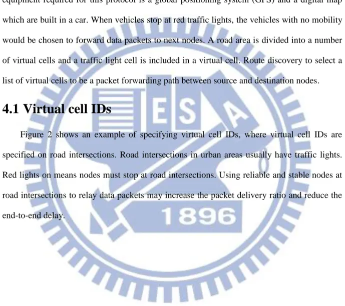
The proposed Traffic Light based Routing (TLR) is a road-based routing protocol. The equipment required for this protocol is a global positioning system (GPS) and a digital map which are built in a car. When vehicles stop at red traffic lights, the vehicles with no mobility would be chosen to forward data packets to next nodes. A road area is divided into a number of virtual cells and a traffic light cell is included in a virtual cell. Route discovery to select a list of virtual cells to be a packet forwarding path between source and destination nodes.
4.1 Virtual cell IDs
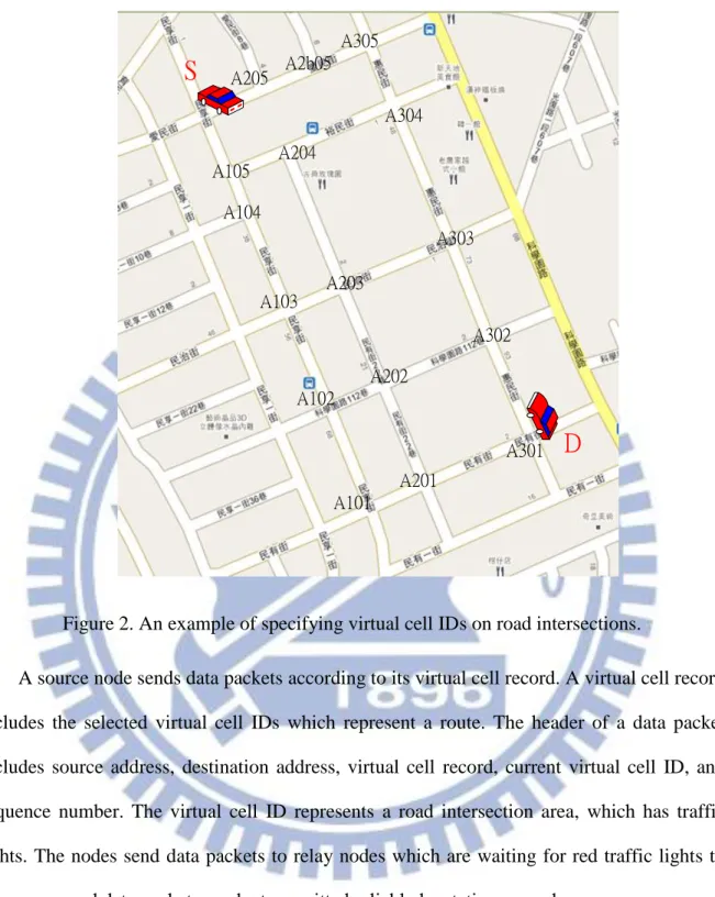
Figure 2 shows an example of specifying virtual cell IDs, where virtual cell IDs are specified on road intersections. Road intersections in urban areas usually have traffic lights. Red lights on means nodes must stop at road intersections. Using reliable and stable nodes at road intersections to relay data packets may increase the packet delivery ratio and reduce the end-to-end delay.
S
D
A101 A201 A301 A102 A103 A104 A105 A202 A203 A204 A302 A303 A304 A205 A2b05 A305Figure 2. An example of specifying virtual cell IDs on road intersections.
A source node sends data packets according to its virtual cell record. A virtual cell record includes the selected virtual cell IDs which represent a route. The header of a data packet includes source address, destination address, virtual cell record, current virtual cell ID, and sequence number. The virtual cell ID represents a road intersection area, which has traffic lights. The nodes send data packets to relay nodes which are waiting for red traffic lights to
11
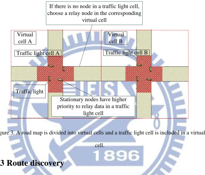
We set nodes’ priorities by backoff delay computation when nodes receive data packets. The backoff delay computation is depicted in section 4.5. If there is no node located in a traffic light cell, the nodes located in the rest of the virtual cell will be chosen to relay data packets.
Virtual cell A
Traffic light cell A
Virtual cell B
Traffic light cell B
Stationary nodes have higher priority to relay data in a traffic
light cell
If there is no node in a traffic light cell, choose a relay node in the corresponding
virtual cell
Traffic light
Figure 3. A road map is divided into virtual cells and a traffic light cell is included in a virtual cell.
4.3 Route discovery
The mechanism of our route discovery is based on CLA [10]. If a source node does not have any route information to the destination node, it broadcasts RREQ packets to find out the destination node. The header of an RREQ packet includes a sequence number which uniquely identifies the packet, source node ID, source node’s virtual cell ID, destination node ID, destination node’s virtual cell ID and virtual cell record which records a list of virtual cells. If an intermediate node receives the same sequence number of an RREQ packet, it discards the packet to avoid broadcasting duplicated packets. If not, the intermediate node attaches its current virtual cell ID into the virtual cell record and forwards the RREQ packet. When the destination node receives the RREQ packet, and it then records its current virtual cell ID and
its direction into an RREP packet. Finally, it sends the RREP packet back to the source node along the route specified in the virtually cell record.
4.4 Data forwarding
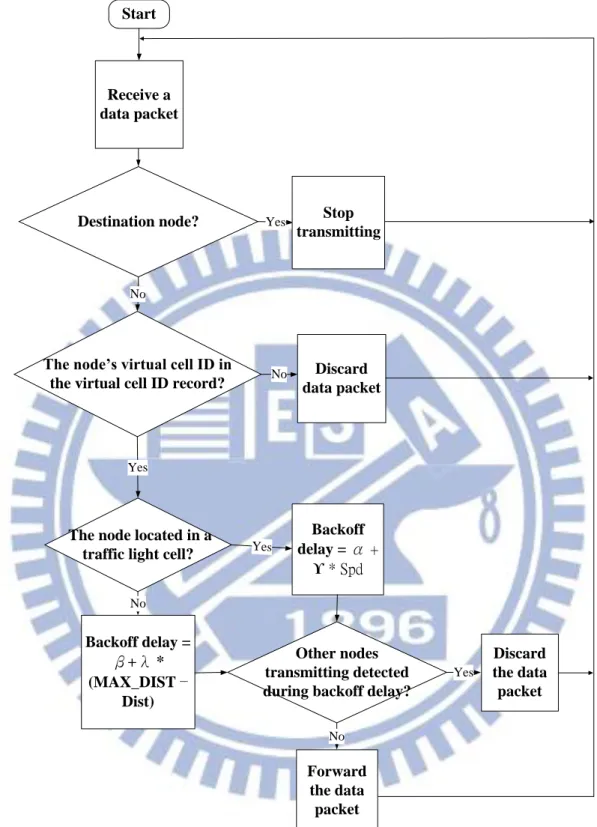
The flowchart of data forwarding from source to destination nodes is shown in Figure 4. A data packet is transmitted from the source to the destination nodes according to a list of selected virtual cell IDs. When a node receives a data packet, it checks if itself is the destination. If it is the destination, stop transmitting; otherwise, it checks if its node’s virtual cell ID is in the virtual cell ID record. If the node’s virtual cell ID is not in the virtual cell ID record, it discards the data packet; otherwise, it runs backoff delay computation. Relay nodes run backoff delay computation to avoid collisions. If a node’s backoff delay is shorter, it has higher priority to relay data packets. The details of the backoff delay computation is described in the next section.
13
Start
Receive a data packet
Destination node?
The node’s virtual cell ID in the virtual cell ID record?
Yes Yes No Stop transmitting Discard data packet No
The node located in a traffic light cell?
No Yes Backoff delay = α + ϒ * Spd Backoff delay = β+λ * (MAX_DIST − Dist) Other nodes transmitting detected during backoff delay?
Discard the data packet Forward the data packet Yes No
4.5 Backoff delay computation
The backoff delay computation of noden receiving a data packet in a traffic light cell of a
virtual cell is computed as follow:
where α is a random number in microseconds (0 ≦ α < 51.2), ɣ is a delay threshold, and
Spdn is the speed of noden.
The backoff delay computation of noden receiving data packet in the rest of the virtual cell is
computed as follow:
where β is a random number in microseconds (51.2 ≦ β < 102.4), λ is a delay threshold,
Distnm is the current distance between node n and the previous node m, and MAX_DIST is the
maximal radio range.
The backoff delay computation of nodei receiving data packet in a traffic light cell of a
virtual cell and in the rest of the virtual cell is summarised as follow:
15
4.6 An example of data forwarding
Figure 5 shows an example of data forwarding. There are some nodes waiting in a traffic
light cell when traffic lights turn red. Since nodes are waiting for the red traffic lights to turn
green, those nodes with no mobility, such as the node with 0 km/hr, will be chosen to forward
data. If no node in traffic light cell, a node which is the farthest from the previous sender are
located in the rest of the virtual cell will be chosen to forward data.
Chapter 5
Simulation and Discussion
For simulation, we chose GlomoSim [16] to evaluate the proposal routing protocol, TLR. GlomoSim is an open source network simulator developed at UCLA and its layered approach is similar to the OSI five-layer network architecture [10].
5.1 Simulation setup
We used two urban scenarios in order to compare the performance of the proposed TLR with two road-based routing protocols, CLA [10] and RBVT [12]. For Glomosim, the area is either 1000 m * 1000 m or 1500 m * 1500 m. The detailed settings of Glomosim are given in Table 3. We chose the VanetMobiSim [14] mobility model to generate mobility traces for simulation. The simulation terrain size is either 1000 m * 1000 m or 1500 m * 1500 m and nodes are placed randomly in the area. A minimum speed of a node is 1 m/s and 11.1 m/s and the maximum speed of a node is 15 m/s and 24.4 m/s for two simulation settings. The number of nodes range from 50 to 250 nodes, the time interval between traffic lights change is set to be 40 seconds, and the radio range of a node is 376 m. The detailed settings of VanetMobiSim
17 generated packets data of number Total packets data received ly Successful ratio delivery Packet
• End-to-end delay: this number indicates the average time from the beginning of a packet transmission (including route acquisition delay) at a source node until packet delivery to a destination measured in millisecond [13].
• Control overhead: it measures the number of routing packets transmitted per distinct data packet delivered to a destination [15].
Table 3. Simulation settings for GlomoSim [16].
Parameters Setting 1 Setting 2
Simulation time(s) 900 300 [12]
Mobility model VanetMobiSim VanetMobiSim
Terrain dimensions 1000 m * 1000 m 1500 m * 1500 m [12]
MAC protocol 802.11 802.11
Source-destination pairs 5 5
Data traffic generation CBR CBR
Packet size (byte) 512 512
Radio transmission range 376 m 376 m
Table 4. Simulation settings for VanetMobiSim [14].
Parameters Setting 1 Setting 2
Simulation time(s) 900 300 [12]
Max traffic lights 80 80
Terrain size 1000 m * 1000 m 1500 m * 1500 m Min. speed 1 m/s (3.6 km/hr) 11.1 m/s (40 km/hr) [12] Max. speed 15 m/s (54 km/hr) 24.4 m/s (88 km/hr) [12] Number of nodes 50, 100, 150, 200 250 [12] Max. acceleration 0.6 m/s2 0.6 m/s2 Normal deceleration 0.5 m/s2 0.5 m/s2
5.2 Simulation results and discussion
In Figure 6, we compare the packet delivery ratio for number of nodes from 50 to 200 between the proposed TLR and CLA routing protocols. The detailed settings for Glomosim and VanetMobiSim are shown in setting 1 of Table 3 and setting 1 of Table 4, respectively. Simulation results show that a larger number of nodes results in a larger packet delivery ratio, due to the increase of network connectivity. The proposed TLR improves the packet delivery ratio by 10.5% compared to CLA, because TLR utilizes stationary nodes or low velocity nodes located in traffic light cells to forward data packets. That is, the routing paths between stationary nodes or low velocity nodes are more reliable [17]. In Figure 7, we compare the end-to-end delay for number of nodes from 50 to 200 between TLR and CLA. Simulation result shows that the proposed TLR improves the end-to-end delay by 29.4 ms compared to CLA. This is because TLR uses the backoff delay computation to avoid collisions and retransmissions. In Figure 8, we compare the control overhead for number of nodes from 50 to 200 between TLR and CLA. Simulation result shows that the proposed TLR improves the control overhead by 0.52 packets compared to CLA. This is due to that TLR uses the backoff delay computation to avoid collisions and retransmissions.
19
Figure 6. Effect of different number of nodes on packet delivery ratio.
Figure 8. Effect of different number of nodes on control overhead.
In Figure 9, we compare the packet delivery ratio under packet rates from 0.5 to 5
packets/s between TLR, CLA and RBVT-P routing protocols. The detailed settings for
Glomosim and VanetMobiSim are shown in setting 2 of Table 3 and setting 2 of Table 4, respectively. Simulation result shows that the proposed TLR performs well, with an improvement of 10.7% packet delivery ratio compared with CLA. TLR has an improvement of 10% packet delivery ratio compared with RBVT-P. In Figure 10, we compare the end-to-end delay under packet rates from 0.5 to 5 packets/s between TLR, CLA and RBVT-P. Simulation result shows that the proposed TLR has better end-to-end delay than CLA and
21
Figure 9. Effect of different packet rate on packet delivery ratio.
Figure 10. Effect of different packet rate on end-to-end delay. 0 0.1 0.2 0.3 0.4 0.5 0.6 0.7 0.8 0.9 1 0.5 1 2 3 4 5
Pac
ket d
el
ive
ry
rat
io
Packet rate (packet/s)
RBVT-R
RBVT-P
TLR (proposed)
CLA
Chapter 6
Conclusion
6.1 Concluding remarks
We have presented a traffic light based routing (TLR) protocol for VANETs that is based on traffic lights of urban areas. An area is divided into numbers of virtual cells and a traffic light cell is included in a virtual cell. When vehicles stop at red traffic lights, nodes with no mobility are selected to forward data to next nodes reliably. Using stable nodes selected by running backoff delay computation to relay data packets can increase the packet delivery ratio and reduce the end-to-end delay. Simulation has shown that the proposed TLR improves 10.5% and 10% of the packet delivery ratio compared to CLA and RBVT-P, respectively. The proposed TLR also reduces 21.3 ms and 82.5 ms of the end-to-end delay compared to CLA and RBVT-P, respectively. Although RBVT-R has the better packet deliver ratio than TLR, its end-to-end delay is much higher than TLR. Delivering packets to a relay vehicle which is waiting for a red traffic light and running backoff delay computation indeed can improve the packet delivery ratio and the end-to-end delay.
23
Bibliography
[1] Y. Toor, P. Muhlethaler, and A. Laouiti, “Vehicle Ad Hoc Networks: Applications and Related Technical Issues,” IEEE Commun. Surveys & Tutorials, pp. 74-88, Third Quarter 2008.
[2] C. E. Perkins and E. M. Royer. “Ad Hoc On-Demand Distance Vector Routing,” in Proc.
2nd IEEE Workshop on mobile comput. Syst. Appl., pp. 90-100, February 1999.
[3] D. B. Johnson and D. A. Maltz, “Dynamic Source Routing in Ad Hoc Wireless Networks,”
Mobile Comput., vol. 353, no. 5, pp. 153-161, 1996.
[4] B. Parkinson and S. Gilber, “NAVSTAR: Global Positioning System – 10 Years Later,” in Proc. of IEEE, vol. 71, no. 10, pp. 1177-1186, Oct. 1983.
[5] M. Gerla, X. Hong, and G. Pei, “Fisheye State Routing Protocol (FSR) for Ad Hoc Networks,” IETF Draft, 2002.
[6] C. E. Perkins and P. Bhagwat, “Highly Dynamic Destination-sequenced Distance-vector routing (DSDV) for Mobile Computers,” in Proc. ACM SIGCOMM Conference. Commun.
Architectures, Protocols Appl., London, U.K., Sep. 1994, pp. 234-244.
[7] P. Jaqcuet, P. Muhlethaler, T. Clausen, A. Laouiti, A. Qayyum, and L. Viennot, “Optimized Link State Routing Protocol for Ad Hoc Networks,” in Proc. of IEEE INMIC
Multi Topic Conference, pp. 62-68, Dec. 2001.
[8] S. Grafling, P. Mahonen, and J. Riihijarvi , "Performance Evaluation of IEEE 1609 WAVE and IEEE 802.11p for Vehicular Commun." in Proc. Second International
Conference on Ubiquitous and Future Networks (ICUFN), pp. 344-348, June 2010.
[9] H. Hartenstein and K. P. Laberteaux, “A Tutorial Survey on Vehicular Ad Hoc Networks,”
[10] A.H. Ho, Y.H. Ho, and K. A. Hua, “A Connectionless Approach to Mobile Ad Hoc Networks in Street Environments,” in Proc. of IEEE Intelligent Vehicles Symposium, pp. 575-582, June 2005.
[11] P. Bose, P. Morin, I. Stojmenovic, and J. Urrutia, “Routing with Guaranteed Delivery in Ad Hoc Wireless Networks,” ACM Wireless. Networks., vol. 7, no. 6, pp. 609-616, Nov. 2001.
[12] J. Nzouonta, N. Rajgure, A. Guiling Wang, and C. Borcea, “VANET Routing on City Roads Using Real-time Vehicular Traffic Information,” IEEE Trans. Veh. Commun. pp. 3609-3626, Sept. 2009.
[13] A. K. Pandey, H. Fujinoki, “Study of MANET Routing Protocols by GloMoSim Simulator,” International Journal of Network Management, vol. 15 no. 6, pp. 393-410, November 2005.
[14] M. Fiore, J. Härri, F. Filali, and C. Bonnet, “Vehicular Mobility Simulation for VANETs,” in Proc. 40th Annual Simulation Symp., pp. 301-307, Mar. 2007.
[15] Y. H. Ho, A. H. Ho, and K. A. Hua, “Routing Protocols for Inter-Vehicular Networks: A Comparative Study in High-Mobility and Large Obstacles Environments, ” Computer
Commun. Journal - Special Issue on Mobility Protocols for ITS/VANET, July 2008.
[16] X. Zeng, R. Bagrodia, and M. Gerla, “GloMoSim: A Library for Parallel Simulation of Large-scale Wireless Networks,” in Proc. Workshop on Parallel and Distributed
25
[19] V. Naumov and T. Gross, “Connectivity-Aware Routing (CAR) in Vehicular Ad Hoc Networks,” in Proc. IEEE Int. Conf. Comput. Commun., pp. 1919-1927, May 2007.
[20] T. Li, S. K. Hazra, and W. Seah, “A Position-based Routing Protocol for Metropolitan Bus Networks,” in Proc. 61st IEEE VTC-Spring, pp. 2315-2319, Jun. 2005.
![Table 1. Comparison of MANETs and VANETs [1]](https://thumb-ap.123doks.com/thumbv2/9libinfo/8744789.204770/12.892.123.807.302.928/table-comparison-manets-vanets.webp)

![Table 3. Simulation settings for GlomoSim [16].](https://thumb-ap.123doks.com/thumbv2/9libinfo/8744789.204770/28.892.136.809.331.1136/table-simulation-settings-for-glomosim.webp)