Airflow velocity effects on air bearing with grooved disk surface in near-field optical
disk drives
H. C. Wang and T. S. Liu
Citation: Physics of Fluids (1994-present) 18, 057103 (2006); doi: 10.1063/1.2194072
View online: http://dx.doi.org/10.1063/1.2194072
View Table of Contents: http://scitation.aip.org/content/aip/journal/pof2/18/5?ver=pdfcov Published by the AIP Publishing
Articles you may be interested in
Direct near-field optical investigation of phase-change medium in blue-ray recordable and erasable disk Appl. Phys. Lett. 95, 103105 (2009); 10.1063/1.3222901
Super-resolution near-field optical disk with an additional localized surface plasmon coupling layer J. Appl. Phys. 91, 10209 (2002); 10.1063/1.1476068
1.5-Mbit/s direct readout of line-and-space patterns using a scanning near-field optical microscopy probe slider with air-bearing control
Appl. Phys. Lett. 76, 804 (2000); 10.1063/1.125590
Transmitted signal detection of optical disks with a superresolution near-field structure Appl. Phys. Lett. 75, 151 (1999); 10.1063/1.124302
Near-field optical recording on the cyanine dye layer of a commercial compact disk-recordable J. Vac. Sci. Technol. A 15, 1442 (1997); 10.1116/1.580558
Airflow velocity effects on air bearing with grooved disk surface
in near-field optical disk drives
H. C. Wang and T. S. Liu
Department of Mechanical Engineering, National Chiao Tung University, Hsinchu 30010, Taiwan, Republic of China
共Received 19 October 2005; accepted 10 March 2006; published online 5 May 2006兲
By means of an air bearing, the pickup head slider of a near-field optical disk drive flies above data tracks on a rotating disk surface to achieve a stable flying height. The influence of airflow velocities of the air bearing on lift force deserves investigation, as the airflow velocity varies during track seeking or disk speed variation. In this study, a direct simulation Monte Carlo method is used to investigate three-dimensional nanoscale gas film lubrication at the air bearing between a slider and a rotating disk. This study aims to investigate air bearing behavior at different airflow velocities. Computational results show that faster flow generates larger pressure and lift force. Lower flying height reduces force variation caused by different velocities. This study also proposes a method for maintaining the flying height within the near-field range. © 2006 American Institute of Physics. 关DOI:10.1063/1.2194072兴
I. INTRODUCTION
To increase data storage density and capacity for multi-media and information technology, near-field optical disk drives represent one of promising devices.1,2For the sake of near-field optics, an optical pickup head slider has to fly above the disk surface at a distance smaller than the mean free path of molecules in the air, i.e., 65 nm at standard at-mospheric pressure共STP兲.
The disk surface under rotation gives rise to airflow, which creates air pressure and provides lift force at the head/ disk interface. Traditionally, macroscopic hydrodynamic equations, e.g., Reynolds equations and Navier-Stokes equa-tions are used to deal with the macroscopic flow behavior. In gas film lubrication problems under submicron or less clear-ance conditions, flow in the gas films cannot be dealt with as continuum flows because the molecular mean free path is not negligible compared to the clearances. Accordingly, they must be treated as rarefied gas flows based on kinetic theory.3 One of the most important parameters in the kinetic theory is Knudsen numbers, which are defined as the ratio of the mo-lecular mean free path to the characteristic length. Burgdorfer4 introduces the concept of the kinetic theory to the field of gas film lubrication and uses a slip flow velocity boundary condition.
A statistics-based method, the direct simulation Monte Carlo共DSMC兲 method presented by Bird5in the early 1970s, can predict the airflow behavior. The DSMC method is ca-pable of dealing with air bearing problems when the slider and disk quasicontact or contact. Alexander et al.6validated DSMC by comparing with Reynolds equation results in rar-efied gas. Huang and Bogy7,8proved that the DSMC method and the modified Reynolds equations yield similar results in the range of Knudsen number up to 6 for minimum spacing of 10 nm. Their simulation results were compared with a slip correction for Reynolds equation, based on the Boltzmann equation. The modified Reynolds equation was introduced by
Fukui and Kaneko9 where the Poiseuille flow rate was cal-culated on the basis of a linearized Bhatnagar-Gross-Krook model10of the Boltzmann equation. Slider posture effects on the air bearing in hard disk drives were examined by Liu and Ng.11For near-field optical disk drives, Wang et al.12 inves-tigated effects of disk surface grooves and compared with results without grooves, according to which the presence of the groove reduces the pressure at the head/disk interface.
A pickup head slider undergoes two motions when flying above a disk. One is track following, in which the slider flies above the disk at the same radial position to read continuous data. The other is track-seeking motion, which occurs in searching data on the disk. To facilitate data reading/writing, stable lift force during track seeking is desired, as lift force variation degrades stability. This study investigates the air bearing for a slider flying above the near-field optical disk at different speeds. The DSMC method is used to develop the air bearing model for pressure distributions in head/disk in-terface at the same position of different disk speeds or at different positions of the same disk speed. This study also concerns the lift force change percentage when airflow ve-locity changes or slider flying height changes. The pressure change percentage can represent stability in track seeking and track following.
II. DSMC METHOD
The air bearing force and flying height analysis are cru-cial for air bearing design. In this study, the flying pickup head slider flies within the range of the mean free path of air molecules 共=65 nm at STP for air兲. Unfortunately, con-tinuum assumption begins to break down when the molecu-lar mean free path becomes comparable to flow character-istic length L. The ratio of these two quantities is known as the Knudsen number共Kn=/L兲 and is usually used to indi-cate the degree of rarefaction. Based on the Knudsen num-ber, flows are divided into four categories:1,3Kn⬍0.01
共con-1070-6631/2006/18共5兲/057103/7/$23.00 18, 057103-1 © 2006 American Institute of Physics
tinuum兲, 0.01⬍Kn⬍0.1 共slip flow兲, 0.1⬍Kn⬍3 共transitional flow兲, and Kn⬎3 共free molecular flow兲. Kn val-ues in this study range from 1.625 to 3.25, corresponding to flying heights from 40 to 20 nm. Hence, the flow in this study belongs to the transitional flow and free molecular flow. This study uses the DSMC method to deal with those rarefied gas problems.
The basic idea of DSMC is to calculate airflows by using the physical foundation rather than mathematical foundation. The assumptions of molecular chaos and dilute air are re-quired in both the Boltzmann formulation and the DSMC method. Molecules move in the simulated physical domain so that the physical time is a parameter in simulation and all flows are computed as unsteady flows. An important feature of DSMC is that the molecular motion and the intermolecu-lar collisions are uncoupled over time intervals that are much smaller than the mean collision time. Both the collision be-tween molecules and the interaction bebe-tween molecules and solid boundaries are computed on a probabilistic basis. Un-like molecular dynamics methods, the DSMC method pro-vides probability and average physical quantities instead of predicting the instantaneous state of each air molecular par-ticle. In practice, the number of simulated molecules is ex-tremely small compared with the number of real molecules. Air molecule inflow and outflow in a simulation region are hard to predict. In order to perform simulation with inflow/outflow pressure boundaries, a general procedure for these conditions by using the concept of particle flux conser-vation has been developed.5Applying particle flux conserva-tion is the basic idea to update the inflow and outflow veloci-ties. At each pressure boundary, the mass flow rate conserves automatically and simulated boundary pressures coincide with the imposed values by assuming thermal equilibrium.
The molecule position in the simulation region is as-sumed of Maxwellian distribution,5 which is written as a function of molecular thermal velocityv; i.e.,
f共v兲 =
冉
 冊
3/2 exp共−v2兲 共1兲 with = m 2kT,where m is the molecule mass, T is the temperature, and k is the Boltzmann constant.
For given mean speed V and temperature, the air mol-ecule flux N˙ across a boundary surface with area A in a particular direction can be determined. The air molecule flux rate in boundary surface A is written as
N˙ A= nVmp兵exp共− q2兲 +
冑
q关1 + erf共q兲兴其 2冑
共2兲 with q = V Vmp cos, Vmp=冑
2kT m ,where n is the number density共number of molecules in unit volume兲 and Vmpis the most probable speed.
By applying the particle flux conservation for each cell
m 共area Am兲 at the inflow pressure boundary, the updated
inflow streamwise velocity at cell m is computed as 共ui兲m=
N˙+− N˙−
niAm
, 共3兲
where N˙+and N˙−are the particle flux into and out of the flow domain for cell m at the inflow pressure boundary using the latest updated共ui兲mand sampled streamwise velocity at each
inflow boundary cell m with number density ni in inflow
stream and temperature Ti. At the outflow pressure boundary,
a procedure similar to that used to treat inflow conditions is carried out for updating outflow streamwise velocity 共ue兲m
for each outflow boundary by applying the principle of par-ticle flux conservation. Note that the outflow temperature for each cell interface is not given in advance and is set to the temperature sampled inside for each outflow boundary cell during simulation.
III. SIMULATION AND RESULTS A. Near-field optical disk drives
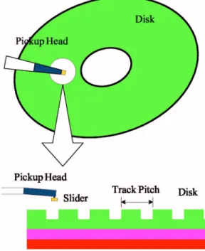
Commercial optical disk drives such as CD-ROM and DVD-ROM read and record data by using the technology of far-field optics. The recording principle is shown in Fig. 1共a兲. However, the far-field optics is constrained by the optical property of diffraction limit and is difficult to further in-crease storage density. The architecture of far-field optical disk drives in reading and recording make the access time longer than hard disk drives. To overcome the bottleneck, near-field optical disk drives are under development to sub-stitute far-field optical disk drives. By taking advantage of the near-field technology, the disk track pitch for near-field FIG. 1. Recording principle of共a兲 far-field and 共b兲 near-field optical disk drives.
057103-2 H. C. Wang and T. S. Liu Phys. Fluids 18, 057103共2006兲
optical disk drives can become much smaller than CD-ROM or DVD-ROM and the storage density can hence be signifi-cantly increased.
Applying near-field optics to avoid the diffraction limi-tation, near-field optical disk drives can further reduce the light spot size to access smaller data track width and accom-plish higher data recording density.1It adopts the structure of magnetic disk drives but replaces the magnetic pickup head slider by a near-field optical pickup head slider to maintain the space between the pickup head slider and disk within a near-field focusing length.2 The recording density can thus be increased by optical resolution improvement. As the flight height is typically smaller than the mean free path of mol-ecules in the air, i.e., 65 nm at STP, microscopic effects in-clude slip length, air-surface accommodation, surface rough-ness, recording groove, etc. are important. The near-field optical disk drives are shown as Fig. 2. In order to overcome the diffraction limit, the flying height between the slider and recording layer in air-incidence phase change disk must be less than 100 nm. For lower distance between the slider and recording layer, the recording method is depicted in Fig. 1共b兲. Figure 3 shows a near-field optical disk with grooved surface, where grooves and lands constitute a trench-like fea-ture of a rewritable optical disk. Before the optical disk records information, lands and grooves are used to define the track location. The pregroove has the following functions: 共1兲 sector configuration,
共2兲 stable tracking servo for reading and recording, and 共3兲 heat isolation for high-density recording.
The groove depth is prescribed as 50 nm. The widths of the groove and land are 100 and 200 nm, respectively. Unlike conventional optical disks, the recording layer of the near-field optical disk is on the disk surface. Hence, the recording tracks with the grooves and lands constitute disk roughness.
The geometry of the near-field optical disk is full of tracks on the disk surface although only two grooves are depicted in Fig. 3. The groove influence is shown between near-field optical disk and smooth disk.12The pressure is smaller when slider flies above the near-field optical disk than that when slider flies above the smooth disk. At such low flying height, the disk groove influence cannot be neglected. Hence, all the simulation in this study deals with the grooved near-field optical disk.
B. Modeling and simulation
Figure 4 shows a three-dimensional共3D兲 slider air bear-ing configuration. Figure 5 shows a slider with three rails that will be investigated in this simulation. A solid immer-sion lense共SIL兲 is treated as the third rail and it is installed at the higher pressure zone on the flat slider because the SIL density is larger than the slider density. The higher pressure zone on the flat slider is shown by Huang and Bogy.7 The length L of the slider used in this simulation is prescribed as 4m and its width W is 3.3 m. The height of rails is 0.7m. The pitch angle␣ is 0.01 rad.
FIG. 2. Pickup head slider and near-field optical disk.
FIG. 3. Grooves and lands in near-field optical disk.
FIG. 4. Three-dimensional DSMC configuration.
To model a disk and a slider, the present model contains two solids in the control volume, where the upper and the lower surfaces are treated as solid. The other four faces of the control volume are treated as fluxing reservoirs in bound-ary condition definition. The four sides act as infinite with thermal equilibrium at temperature T0 and ambient pressure
P0. The flow velocities in the reservoirs are such that the pressure on all four sides can be maintained at pressure P0,
but this study uses the air property at STP. Triangular ele-ments are used in the solid surface grids. The points order defined for each triangular element is counterclockwise when looking from outside the surface. Figure 6 shows triangular elements of a parallelepiped. Orders of the points in two triangular elements are thus 1-3-2 and 1-4-3. The outward normal of the solid can be identified according to the right-hand rule by tracing the order of points in an element. For example, the arrow in element with node 1-3-2 shows the outward solid surface direction in Fig. 6. The arrow direction is determined by using the right-hand rule which traces the sequence nodes in elements.
To obtain detail pressure distribution, each length of tri-angular elements has to be shorter than the mean free path 65 nm of the air. The disk grooves depth is prescribed as
50 nm in this study. To achieve the grid of the disk model, the disk groove depth should be divided by the length of triangular element with no remainder. As the slider bottom is symmetric with respect to its longitudinal axis, only half of the slider is required in the present model. Employing this symmetry reduces the model size and computation time.
The air under the slider is assumed to be dilute so that the potential energy of particles is negligible compared to the kinetic energy. As the real air is mixed by 4 / 5 nitrogen and 1 / 5 oxygen, it is complicated to deal with polyatomic mol-ecules and mixed air using DSMC. Based on the previous assumptions, as the potential energy and the mean free path of air molecules are similar to those of argon, instead of real air molecules this study uses argon of temperature T0
= 0 ° C and density = 1.78 kg/ m3 in computing averaged
quantities, including momentum and kinetic energy.
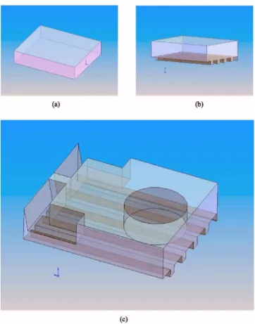
Figure 7共a兲 shows the entire simulation region filled with FIG. 5. Slider geometry.
FIG. 6. Outward surface on solid is indicated as arrow directions.
FIG. 7.共a兲 Original simulation region; 共b兲 simulation region after disk sur-face is subtracted; and共c兲 simulation region after disk surface and slider bottom are subtracted.
FIG. 8.共a兲 Parallelepipeds and 共b兲 subparallelepipeds.
057103-4 H. C. Wang and T. S. Liu Phys. Fluids 18, 057103共2006兲
argon and Fig. 7共b兲 shows the simulation region after sub-traction of a disk. The final region used in simulation is shown as Fig. 7共c兲 that has subtracted a slider from Fig. 7共b兲. Except the solid region, the simulation region is filled with parallelepiped elements, which are filled with subparallelepi-ped elements. Figure 8共a兲 shows the parallelepisubparallelepi-ped elements and Fig. 8共b兲 shows subparallelepiped elements defined. In this study, the parallelepiped element size is 50 nm ⫻50 nm⫻5 nm. Each parallelepiped element consists of four subparallelepiped elements, whose size are 25 nm ⫻25 nm⫻5 nm.
C. Results
Figure 9共a兲 shows pressure distribution on the slider that
may account for two situations. First, the slider keeps 20 nm flying height above a rotating near-field optical disk with 3600 rpm at the radial distance of 2.65 cm from the disk center. Second, the slider maintains 20 nm flying height above a rotating disk and the slider position along the radius direction depends on the disk speed to keep the airflow ve-locity constant. Figure 9共b兲 shows the slider pressure distri-bution in the same condition except the slider flying height of 30 nm. This section will show how disk speed affects lift force in track following or track seeking. In addition, this section also suggests where to tune the stable slider flying height so as to reach the near-field range by changing disk speed.
1. Track following
From the literature,12 a slider flying above a near-field optical disk results in smaller pressure than flying above a smooth surface disk. The lift force for the same slider when flying above a disk with surface grooves is lower than when flying above smooth disks. How to obtain lift force large enough to maintain air bearing is critical in near-field optical disk drives for reading and writing. For near-field optics, smaller lift force generates lower flying height; i.e., shorter distance between the head and disk to realize higher resolu-tion of reflective laser signals from a disk surface.
Figure 10 shows the relationship among the lift force, flying height, and disk speed. Faster speed results in larger lift force. Table I shows the relationship among the disk speed , airflow velocityv, and slider position r along the
disk radial direction. This relationship in Table I is calculated from
v = r. 共4兲
According to Fig. 10, the higher speed leads to larger lift force in track following. The lift force at 25 nm height and 10 m / s speed is larger than that at 20 nm height and 3.3 m / s speed. As a consequence, faster disk speed can compensate lift force loss when flying higher.
FIG. 9.共Color兲 Pressure distribution at 10 m/s airflow speed on slider bot-tom for slider flying heights of共a兲 20 nm and 共b兲 30 nm.
FIG. 10. Relationship among the lift force, flying height, and airflow speeds in track following.
This study defines lift force stability as the ratio of lift force at arbitrary flow speed vs. lift force at flow speed of 3.3 m / s. If the force change percentage is close to 100%, it means that force variation is smaller and is treated as more stable. Figure 11 shows that lift force decrease percentage varies with both flying height and disk speed. Both this result and that presented by Huang and Bogy7show that lift force increases when the slider is closer to the disk whether the disk surface is grooved. Figure 11 depicts that at 10 m / s speed the lift force decrease rate is the smallest when flying height varies. Accordingly, the faster disk speed is advanta-geous for track following.
2. Track seeking
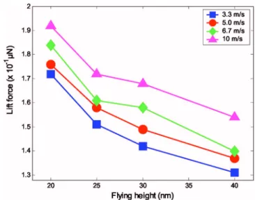
In track seeking at constant disk speed, the linear veloc-ity varies with the radial position. Figure 12 shows that faster airflow generates larger lift force. In addition, the lower height yields a larger force. This result is similar to the re-sults when a slider flies above a disk without grooves.6 By comparing 20 and 25 nm flying heights, the lift force of the 20 nm flying height at any speed is larger than the largest lift force of 25 nm flying height at 10 m / s.
When the slider position changes at the same disk speed, the flow velocity at the head/disk interface changes. Table I lists the relationship among the disk speed, airflow velocity,
and slider position along the disk radial direction when the disk diameter is 3.5 in.. Figure 13 shows the force change percentage relative to the 3.3 m / s velocity at each flying height when the slider position changes. A faster velocity results in a larger lift force. Therefore, flying lower is more stable when airflow velocity varies.
During track seeking, the slider position change makes the flow speed change. To maintain a stable flying height, minimizing lift force change is desired. Figure 13 depicts that flying lower experiences smaller lift force variation. Hence, in track seeking, it is advisable to fly as low as pos-sible to increase stability.
In track seeking, variations of slider position along the disk radial direction lead to flow velocity changes. This re-lationship between slider position and flow velocity is shown in Table I. The air bearing results from airflow whose veloc-ity change results in the bearing force change. In track seek-ing, there are two variations. One is the flow speed. The TABLE I. Slider radial position共cm兲 corresponding to disk speed and
air-flow velocity. Disk speed共rpm兲 Airflow velocity共m/s兲 10.0 6.7 5.0 3.3 3600 2.65 1.76 1.32 ¯ 2400 3.98 2.65 1.99 1.32 1800 ¯ 3.54 2.65 1.76 1200 ¯ ¯ 3.98 2.65
FIG. 11. Lift force decrease percentage when flying height increases in track following.
FIG. 12. Relationship among the lift force, flying height, and airflow speeds in track seeking.
FIG. 13. Lift force increase percentage when airflow speed increases in track seeking.
057103-6 H. C. Wang and T. S. Liu Phys. Fluids 18, 057103共2006兲
other is the slider flying height change. Figure 12 shows that the lift force increases when the slider is closer to the disk. Hence, in track seeking, the slider seldom crashes even if the flow speed decreases. This study suggests to tune a stable flying height at the outer rim of the disk by changing the disk speed and the tuning steps are shown in Fig. 14. First, let the spindle motor rotate at a high speed and the slider move toward the disk. Second, let the slider move to reach a posi-tion above the disk outer rim and slow down the disk speed until the slider flies lower to lie within near-field range. When the slider moves closer to disk center at constant disk speed, the airflow slows down according to Eq.共4兲. How-ever, the air bearing force will not be able to support the slider at the flying height. The slider hence further lowers its flying height to obtain new equilibrium among the lift force, pickup head elasticity, and gravitational force. Accordingly, the slider flying height can be maintained within the near field. Finally, move the slider to arrive at a target track on disk surface.
IV. CONCLUSION
This study investigates influence of the airflow velocity when a slider flies above a near-field optical disk. Computa-tional results show that at the same flying height the higher flow velocity generates larger lift force. Faster airflow is more stable when the flying height changes. In track follow-ing, it is desired to maintain a faster velocity for stability. In track seeking, this study suggests that a stable flying height be obtained at an outer track on the disk by varying the disk speed, so as to maintain the slider flying height within the near field.
ACKNOWLEDGEMENT
This work was supported by ”Photonics Science and Technology for Tera Era,” Center of Excellence, National Science Council, Taiwan under Grant No. 94-E-009-009-PAE.
1T. D. Milster, “Near-field optics: A new tool for data storage,” Proc. IEEE
88, 1480共2000兲.
2K. Ito, H. Saga, H. Nemoto, and H. Sukeda, “Advanced recording method
using a near-field optics and the GMR head,” in Proceedings of the Optical Data Storage, Conference Digest, Whistler, Canada, 2000, Vol. 14–17, p. 30.
3E. H. Kennard, Kinetic Theory of Gases: With an Introduction to
Statisti-cal Mechanics共McGraw-Hill, New York, 1938兲.
4A. Burgdorfer, “The influence of the molecular mean free path on the
performance of hydrodynamic gas lubricated bearings,” ASME J. Basic Eng. 81, 94共1959兲.
5G. A. Bird, Molecular Gas Dynamics共Clarendon, Oxford, 1976兲;
Molecu-lar Gas Dynamics and the Direct Simulation of Gas Flows共Oxford Uni-versity Press, New York, 1994兲.
6F. J. Alexander, A. L. Garica, and B. J. Alder, “Direct simulation Monte
Carlo for thin-film bearings,” Phys. Fluids 6, 3854共1994兲.
7W. Huang and D. B. Bogy, “Three-dimensional direct simulation Monte
Carlo method for slider air bearings,” Phys. Fluids 9, 1764共1997兲.
8W. Huang and D. B. Bogy, “An investigation of slider air bearing with an
asperity contact by a three-dimensional direct simulation Monte Carlo method,” IEEE Trans. Magn. 34, 1810共1998兲.
9S. Fukui and R. Kaneko, “Analysis of ultra-thin gas film lubrication based
on linearized Boltzmann equation: First report—derivation of a general-ized lubrication equation including thermal creep flow,” J. Tribol. 110, 253共1988兲.
10P. L. Bhatnagar, E. P. Gross, and M. Krook, “A model for collision
pro-cesses in gases. I. Small amplitude propro-cesses in charged and neutral one-component systems,” Phys. Rev. 94, 511共1954兲.
11N. Liu and E. Y. K. Ng, “The posture effects of a slider air bearing on is
performance with a direct simulation Monte Carlo method,” J. Magn. Magn. Mater. 11, 463共2001兲.
12H. C. Wang, T. S. Liu, and C. S. Chang, “Study of air bearing with
grooved disk surface in near-field optical disk drives,” IEEE Trans. Magn.
41, 1047共2005兲.
FIG. 14. A method for keeping the flying height within near field in track seeking.