The design and development of a hydrostatic extrusion apparatus
Jung-Chung Hung
a, Chinghua Hung
b,*aDepartment Mechanical Engineering, National Chin-Yi Institute of Technology & Commerce, Taipei, Taiwan, ROC bDepartment of Mechanical Engineering, National Chiao Tung University, 1001 Ta Hsueh Road, Hsinchu 300, Taiwan, ROC
Received 14 February 1999
Abstract
The purpose of this research is to design and construct an experimental hydrostatic extrusion apparatus which has a maximum working pressure of 10 000 kg/cm2, and to reduce the cost of this extrusion apparatus. The high-pressure extrusion container has been designed with
two-layer pyramidal cylinders, and the material used was SKD61 which is cheap and readily available. Different materials and designs for high-pressure seals were tested and analyzed for the best combination performance. Problems in the extrusion processes using this device were analyzed and solved, which increased the reliability of the device. The results of extrusion experiments have established that this device is practicable. # 2000 Published by Elsevier Science S.A.
Keywords: Hydrostatic extrusion apparatus; High pressure; Composite clad rods; Hydrostatic extrusion test
1. Introduction
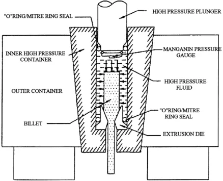
Progress of technology has caused the development of new materials to ful®ll new engineering demands, e.g., new alloys, powder of ceramics and superconductors, etc. These new materials are often dif®cult to produce. Among the new processes that were developed in recent years to produce these new materials, hydrostatic extrusion appears to have the greatest potential. The difference between the conven-tional extrusion and hydrostatic extrusion is that the latter uses ¯uid (high-pressure ¯uid) as pressure-transmitting medium instead of direct contact. During the extrusion, this ¯uid transmits a hydrostatic pressure to the billet, which can largely increase the ductility of the extrusion materials. This ¯uid also acts as a lubricant between the die and billet and results in a near frictionless operation. Therefore the process is capable of extruding many dif®cult-to-deform materials. The extrusion machine can be divided into seven parts: (1) a high-pressure extrusion container, (2) a high-pressure seal, (3) a high-pressure source, (4) a high-pressure plunger, (5) a pressure intensi®er device, (6) a manganin pressure gauge, and (7) back pressure equipment (Fig. 1). The cost of a typical hydrostatic extrusion device is very high compared to that of a traditional device, therefore, to design a practical
and commercially viable device has become an important engineering topic.
The idea of hydrostatic extrusion was ®rst established by Robertson [1], but the method was ®rst experimented by Bridgman [2]. Later research and development work was carried out by Pugh [3] and his colleagues. They developed the back pressure system in 1964 [4], that can prevent the cracking of brittle material in simple hydro-static extrusion. Following this, further research and experi-mentation was done at High Pressure Laboratory of the Academy Sciences of the USSR, as well as in the USA, and Japan.
The disadvantage of simple hydrostatic extrusion is that the extrusion speed is uncontrollable. Slater and Green [5] presented the way of ``augmented hydrostatic extrusion'' to overcome this problem. With this method, when the ¯uid pressure is insuf®cient to extrude the billet, an additional force is applied to the rear end of the billet by a solid ram. The extrusion speed can thus be well controlled. However, the length of the billet is then limited by buckling under the axial compressive force of the ram.
When Bridgman experimented with hydrostatic extru-sion, he observed a severe ¯uctuation in the pressure, which was related to the ``stick and slip phenomenon''. This happened because the ¯uid is compressible under the high pressure. When extrusion begins, there is a sudden drop in pressure and the extrusion process then stops until the pressure builds up again. Crawley [6] introduced a method to overcome the ``stick and slip phenomenon''.
*Corresponding author. Tel.: 886-35-712121; fax: 886-35-720634.
E-mail address: [email protected] (C. Hung).
0924-0136/00/$ ± see front matter # 2000 Published by Elsevier Science S.A. PII: S 0 9 2 4 - 0 1 3 6 ( 0 0 ) 0 0 5 9 3 - 8
He built a hydrostatic extrusion machine in which the volume of oil and the speed of the ram can be matched to prevent the occurrence of the phenomenon. Later, Duf®ll [7] designed a cross-bore arrangement hydrostatic extrusion
machine which had a maximum design pressure of 40 t/in2
(about 6200 atm pressure). The advantage of this arrange-ment is that the rams never need to be withdrawn from the ram chamber, which reduces the machine cycle time. These developments simpli®ed the hydrostatic extrusion machine and decreased its cost.
Today, the usage of hydrostatic extrusion is still limited to special applications such as golden-wire making for the semiconductor industry. The main cause obstructing the development is the cost of the device. Therefore, the topics of this research are not only to design and construct a hydrostatic extrusion device but also to solve problems during its operation and to simplify the equipment by using commercially available materials.
2. The design of a hydrostatic extrusion apparatus 2.1. High-pressure source
The high pressure of this experimental hydrostatic extru-sion apparatus comes form the compressed ¯uid in a pres-sure container (Fig. 1). This cylindrical prespres-sure container has an inner bore, 16 mm in diameter, ®tted to a plunger. When a universal-testing machine with maximum capacity of 20.2 t is used to compress the ¯uid in the container through this plunger, a magni®ed ¯uid pressure as high as 10 000 kg/cm2(about 10 000 atm pressure) will be obtained
in the pressure container.
2.2. High-pressure extrusion container
One of the most important components of this apparatus is the container that is required to contain the die, high-pressure ¯uid and billet. According to Lame's equation for a thick wall cylinder [8], the maximum stress at the internal wall of cylinder will reach 19 000 kg/cm2when an
internal pressure of 10 000 kg/cm2is applied. For a design
with single layer cylindrical container, very expensive and rare materials will be required, which is just in contrast with the present goal. Therefore, a two-layer cylinder was adopted in this design as the pressure container, and the material chosen is SKD61 tool steel, which is relatively cheap and commercially available. The properties that need to be considered include surface ®nishing accuracy, material yielding and cracking criteria, seal design and elastic bend-ing problems. Two main processes in the design of this hydrostatic extrusion container, are explained in the follow-ing sections.
2.2.1. Two-layer cylinder design process
The yield stress for SKD61 is about 16 000 kg/cm2. By
taking 1.5 as the safety factor from Manning [9], 10 600 kg/ cm2is derived as the working stress during the design phase.
The condition of yielding at the bore of the outer layer is sy P12 2k 2 2 k2 2ÿ 1 Pi 2k2 1 k2ÿ 1
where sy is the design working stress of material, k the
diameter ratio of the composite cylinder, k1the diameter
ratio of the internal cylinder, k2the diameter ratio of the
external cylinder, P12 the interface pressure between two
layers of the cylinder, and Pithe internal pressure.
The designed diameter for the bore of the internal cylinder is 16 mm for this experimental apparatus. If 48 and 192 mm were chosen as the outer diameters for the internal and external cylinders, respectively, then we get 3, 4, and 12 as the values of k1, k2, and k, respectively. For an input of
100 kg/mm2for P
i, an interface pressure P12 of 44.05 kg/
mm2 was calculated. To obtain the interface pressure of
44.05 kg/mm2between the layers of the cylinder, the radial
interference can be calculated by an equation from Timoshenko [8] d 2P12r32 E r2 3ÿ r21 r2 2ÿ r21 r32ÿ r22
where d is the radial interference, P12the interface pressure
between two layers of the cylinder, r1the inner radius of the
internal cylinder, r2the outer radius of the internal cylinder,
r3 the inner radius of the external cylinder, and E the
modulus of elasticity.
The value of radial interference calculated is 0.24 mm, which is dif®cult to be accomplished by the direct or shrink ®t of two cylinders. Tapered cylinders are then used to solve this problem, and a small taper angle of 28 was chosen for this purpose. When the tapered cylinders were ®tted into each other, a great axial force of around 75 t was required. 2.2.2. Finite-element simulation
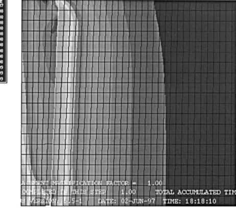
The ®nite-element code ABAQUS/standard was used to verify the design based on equations. Two steps were
simulated. The ®rst one was to simulate the ®tting of the internal container into the external container. The second one was to simulate the condition when high pressure with a magnitude of 10 000 kg/cm2was applied to the inner surface
of this two-layer pressure container. The ®nal Mises stress contour (Fig. 2) shows that the stress is only a little different from that derived from using the equations. However, a point with larger stress value appears at the bottom of the high-pressure container, which may decrease the designed safety factor. Therefore, ®nite-element simulation becomes more important when a hydrostatic extrusion device with higher working pressure is being designed.
2.3. High-pressure plunger
The functions of the high-pressure plunger are both to seal the container and to build the pressure. When the plunger is forced into the container, the pressure of the compressed ¯uid will increase. When the pressure reaches a certain value, the billet will then be extruded. Generally, the plunger will sustain a great axial force that might cause buckling, therefore, the clause No. 1.5.13 of the American Institute of steel construction (AICS) was adhered to, for the design of this plunger. Basically, AICS stipulates the allowance of compressive stress for taking axial force.
The material used for the high-pressure plunger was tungsten carbide (USA C10), which can withstand a pressure of 395 kg/mm2. After computing the slenderness ratio and
the geometrical parameters according to AICS, it was found that plastic-buckling criterion should be used for the design.
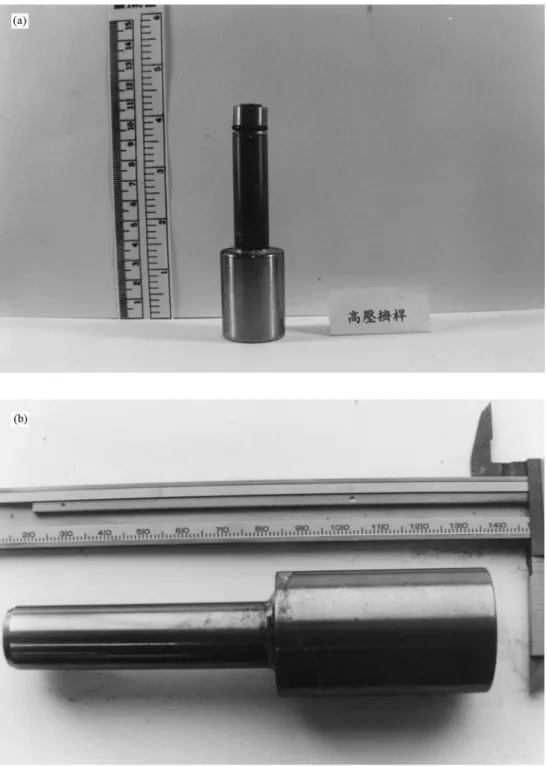
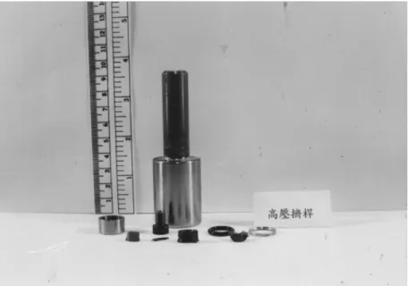
The front section of the plunger has a smaller diameter (f 12 mm) and an inclined plane. This design is for ®tting both a high-pressure ``O'' ring seal and a beryllium copper mitre ring. A metal barrel is screwed on the top to prevent the ``O'' ring seal and mitre ring from sticking in the extrusion container when retracted from the container (Fig. 3). 2.4. High-pressure seal
The design of the high-pressure seal was ®rst introduced by Bridgman [10]. It consists of an ``O'' ring backed by a
metal backup-ring. When the pressure increases the friction will also increase between the backup-ring and the container and thus results in an additional torsion moment. Whalley [11] developed a ladder-shaped cross-section ring to over-come this problem. The seal used for this hydrostatic extrusion apparatus is a P serial ``O'' rings. It can be used
up to a pressure of 210 kg/cm2. In order to prevent the
leakage due to high pressure, the bottom of ``O'' ring is supported by a metal backup-ring. The inclined plane of the backup-ring is tightly ®tted onto both the ``O'' ring and the plunger and thus prevents the ``O'' ring from being squeezed
into the gap. High strength material of beryllium copper is used for backup-ring. This material has a hardness of HRC40. The shape of the backup-ring is similar to that of Whalley's design with 16 mm outer diameter and 1.5 mm thickness. The inclined angles with respect to the ``O'' ring and plunger are 22.5 and 458, respectively.
2.5. High-pressure ¯uid
The ¯uid surrounding the billet has two functions, i.e. to transmit pressure and to lubricate the interface between the billet and the die. Under high pressure, the properties required for the ¯uid include compressibility, good lubrica-tion and stability. In this research, castor oil R68 is chosen as the pressure ¯uid, which has a speci®cation of 15 000 kg/
cm2maximum pressure.
2.6. Back pressure system and manganin pressure gauge The back pressure system is used to control the process of extrusion and to improve the quality of extruded products. The system is divided into three parts: the main body of back pressure source, a hydraulic intensi®er and a back pressure container. This equipment has been designed and built but has not yet been used in the present study.
Most of the hydrostatic extrusion apparatuses use resis-tance pressure gauges. The principle of this kind of pressure gauge is that the resistance of certain metal wire will change slightly with different pressure. This relationship can be calibrated and be used to measure the pressure. The design of the pressure gauge has been incorporated into another research project of the authors group. In this research, the extrusion pressure was derived from the applied force indicated on the universal-testing machine.
3. Preliminary tests and improvements of a hydrostatic extrusion apparatus
3.1. Preliminary tests
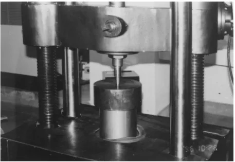
After each component of the apparatus was built up and assembled according to the above design, preliminary tests that pressurize the system without the extrusion process are to be conducted. The set-up is shown in Fig. 4. In this research, a 10 000 kg/cm2hydrostatic pressure is designed
for extrusion. Therefore, 20 110 kg force is applied to the high-pressure plunger by the universal tester. The results of this test show that no leakage and failure occur during the process, which veri®ed that the high-pressure plunger, con-tainer and seals can safely sustain a 10 000 kg/cm2
hydro-static pressure. However, through a series of repeated tests, some problems were found.
3.1.1. The scratches of the high-pressure container Some scratch marks appeared after the tests and resulted in ¯uid leakage even when the pressure is below 10 000 kg/ cm2. These scratches were located on the inner surface of the
container, and they were obviously caused by the cutting effect of the high-pressure plunger and metal mitre ring. 3.1.2. The damage of high-pressure seal
After a few tests, the metal mitre ring showed plastic deformation. The bottom of mitre ring became very sharp and was responsible for the scratches mentioned above. The most probable cause for this problem is the moving seal design that had been used. With this original design, the mitre ring had been moving with the plunger and was subjected to plastic deformation because of the high pressure and relative friction with respect to the container surface.
3.1.3. The brittle fracture of high-pressure plunger The front section of the high-pressure plunger was broken in the last of the repeated tests (Fig. 5). The material of high-pressure plunger is tungsten carbide, which is a highly brittle material. During the tests, stress was concentrated at the cap in the front section. Furthermore, when the pressure reached 10 000 kg/cm2, the metal mitre ring was very tight against
the inner container. When the pressure from the universal tester was suddenly released, the mitre ring could not with-draw from the inner container immediately. Therefore the front section of the plunger, where the stress was concen-trated, received a great shock force, which resulted in a broken front section.
3.2. Design improvements
To overcome the above problems, a ®xed seal located on the high-pressure container was designed to replace the movable seal on the plunger. Other modi®cations include the following:
1. The front section of the plunger was shaped into a bevel and was well polished.
2. The mitre rings of the seals were changed into V shape in cross-section (Fig. 6).
3. On top of the high-pressure container, a circular groove was designed for placing O-ring and metal mitre ring. A Fig. 5. The broken pieces of the high-pressure plunger.
texture was designed to ®x the O-ring and metal mitre ring ®rmly into the groove (Fig. 6).
Experiments with the same procedure as before were undertaken after the modi®cations. The results showed that problems of scratches, plastic deformation and brittle frac-ture no longer existed.
4. The hydrostatic extrusion experiments
Hydrostatic extrusion experiments were conducted using the above apparatus to test its practicability as well as to observe the properties of materials after high-pressure extru-sion. The processes of the experiments are discussed in the following sections.
4.1. Parameters of extrusion
The extrusion ratio is 9 in the experiments. This ratio was selected for the extrusion experiments of both solid alumi-num alloy and powder±solid composite clad rod. A half die angle of 158 was chosen, which appeared to be a suitable value from experience.
4.2. Extrusion die
The design of a hydrostatic extrusion die is more com-plicated than that of a traditional die. Special concerns include the high-pressure sealing and high material strength. In this experiment the inner diameter of the extrusion container is 16 mm, which limits the size of the billet. Therefore, the upper section of die was set to 14 and 16 mm in outer diameter with a ladder-shape. Between these two levels an 458 inclined plane was designed to hold the metal mitre ring of high-pressure seal. For the present speci®c extrusion ratio, the exit diameter of die was set to 3 mm. The material used for the extrusion die (Fig. 7) is SKD61 that had been heat-treated to a hardness of HRC53.
4.3. Extrusion billet
The billets designed for hydrostatic extrusion experiment had the shape of a bullet. The front ends of the billets were turned to a cone shape of 30 and were polished in order to ®t into the die entrance tightly without any leakage of ¯uid. Two types of billets were tested to explore the effects of hydrostatic extrusion. The ®rst type of billets was made from solid rod of aluminum alloy (A6061). The other type of billets were powder/solid metal composite clad rods. For this type of billets, the same aluminum alloy used in the ®rst type was used for the shells of the composite rods, and super-conductive powder (Y±Ba±Cu±O with an average diameter of 5 m) was ®tted into the shells as the core. Two core diameters, 3 and 4 mm, were tested in the experiments. 4.4. Process of extrusion
The extrusion apparatus was set up with the following steps. First, the high-pressure seal was set on top of extrusion die, and then the billet was forced to make tight contact with the die. Afterwards, this assembled die set was placed at the bottom of the high-pressure container. Finally, after the container was ®lled up with pressure ¯uid, the plunger was placed on top of the container and the extrusion process started.
For the powder/solid composite clad rod, an extra step of powder ®lling was required. The weight of powder was ®rst measured and then converted into a density value through calculations. Two densities, 2 and 3 g/cm3, were selected for
the billets with 3 mm diameter cores, and one density, 2 g/ cm3, was chosen for the billets with 4 mm diameter cores.
After the powder had been poured into the hollow billets uniformly and the lids covered tightly, the composite clad rods were ready for extrusion. The speed of extrusion was maintained at approximately 1.2 mm/min.
5. Results and discussion
This section summarizes and discusses the results of the hydrostatic extrusion on two types of billets.
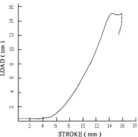
5.1. Hydrostatic extrusion of a solid aluminum alloy rod The diagram of load vs. stroke (Fig. 8) shows that after the force of the plunger reached 14 000 kg (equivalent to 6963 kg/cm2), it then decreased to 13 500 kg and remained
at this value steadily. The maximum pressure value, which is slightly higher than the steady value results from the static friction between the billet and die. After this friction had been overcome by the applied pressure, the billet began to be extruded and the pressure dropped. This constant pressure period indicated that the billet had been extruded out steadily during this time until a preset 2 mm displacement of the plunger was reached. Note that, without a back-Fig. 7. The extrusion die.
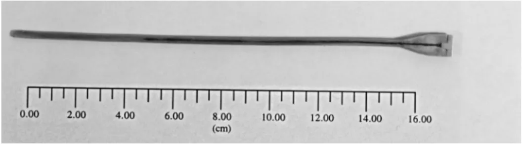
pressure device, it would not have been possible to control the magnitude of the hydrostatic pressure at which the billets were extruded. The surface of the extruded product is very smooth without any peeling (Fig. 9).
5.2. Hydrostatic extrusion of powder/solid composite clad rods
For billets with a 3 mm diameter core, the diagram of load vs. stroke (Figs. 10 and 11) shows that there may exist two stages of deformation. Comparing the diagrams with the cross-sections of the extruded products shown in Figs. 12 and 13, it is possible to identify that these two stages of
deformation should correspond to the deformation of the front end metal without powder and the deformation of both the powder and clad metal, respectively. For different pow-der ®lling densities, the higher the density, the higher is the extrusion pressure and larger the diameter of the extruded powder cores. Nevertheless, for the billets with 3 mm dia-meter cores, the surfaces of the products are all smooth without any peeling and the diameters of all the powder cores are very uniform.
For billets with 4 mm diameter cores, the diagram of load vs. stroke (Fig. 14) also shows two stages of deformation: however, the curves ¯uctuate more after the powder had been extruded. By examining the cross-section of the extruded products (Fig. 15), it was found that both the outer diameter of the clad metal and the diameters of the powder Fig. 8. Load vs. stroke for the extrusion of a solid aluminum alloy rod.
Fig. 9. The extruded product of a solid aluminum alloy rod.
Fig. 10. Load vs. stroke for the extrusion of a powder/solid composite clad billet with a 3 mm (2 g/cm3) diameter core.
Fig. 11. Cross-section of an extruded powder/solid composite clad billet with a 3 mm (2 g/cm3) diameter core.
Fig. 12. Load vs. stroke for the extrusion of a powder/solid composite clad billet with a 3 mm (3 g/cm3) diameter core.
Fig. 13. Cross-section of an extruded powder/solid composite clad billet with 3 mm (3 g/cm3) diameter core.
Fig. 14. Load vs. stroke for the extrusion of a powder/solid composite clad billet with a 4 mm (2 g/cm3) diameter core.
core are not uniform, but are wavy along the length of the extruded rods. Possible explanations of this phenomenon are still awaiting further investigation, but could be related to the ¯ow characteristics of the powder. Compared to metals, powders show poor ¯owability because of the friction between grains and they might accumulate at certain core sections if a suf®ciently large quantity of powder is extruded.
In brief, the results of hydrostatic extrusion, similar to traditional extrusion, are in¯uenced by many extrusion parameters, such as extrusion speed, die angle, material of billets, initial density and quantity of powder core, and even the geometrical shapes and grain sizes of powder. More speci®c and detailed experiments have been designed and further investigations with this hydrostatic extrusion appa-ratus will be undertaken.
6. Conclusions
In this research, an experimental hydrostatic extrusion apparatus was designed, built and modi®ed with emphases on both simplicity of structure and low cost with commer-cially available materials. Two types of billets were extruded using this apparatus to verify its practicability. Satisfactory testing results were obtained together with some information on the material behavior under hydrostatic pressure. While further investigations on the effects of hydrostatic extrusion parameters are going to be carried out, several conclusions may be summarized at this stage.
1. The high-pressure container with a two-layer tapered composite cylinders design has been proven to sustain a
maximum working pressure of 10 000 kg/cm2safely.
2. Although the design of movable seals is more simple than that of ®xed seals, it still cannot sustain high
pressure repeatedly. Therefore, ®xed seals are suggested for high-pressure hydrostatic extrusion apparatus. 3. For precisely controlling the magnitude of the
hydro-static pressure at which the billets are extruded, a back-pressure device is needed.
Acknowledgements
The authors would like to thank the National Science Council of Taiwan, ROC for the grant NSC86-2212-E-009-015, under which the investigation was undertaken. References
[1] J. Robertson, Method of and apparatus for forming metal articles, British Patent No. 19 356 (October 14, 1893); US Patent No. 524 504 (August 14, 1894).
[2] P.W. Bridgman, Studies in Large Plastic Flow and Fracture, McGraw-Hill, New York, 1952.
[3] H.Ll.D. Pugh, D. Gunn, in: International Symposium on the Physics and Chemistry of High Pressures, Society of Chemical Industry, London, 1963, pp. 157±159.
[4] H.Ll.D. Pugh, A.H. Low, The hydrostatic extrusion of dif®cult metals, J. Inst. Met. 93 (1964±1965).
[5] H.K. Slater, D. Green, Proc. Inst. Mech. Engrs 182 (1967±1968). [6] J. Grawley, J.A. Pennell, A. Saunders, Proc. Inst. Mech. Engrs 182
(1967±1968) 180.
[7] A.W. Duf®ll, P.W. Mellor, The design and development of hydrostatic extrusion machine, Int. J. Mach. Tools Des. Res. 18 (1968) 125±140.
[8] S. Timoshenko, Strength of Materials, Part II, Van Nostrand, Princeton, NJ, 1930.
[9] W.R.D. Manning, The design of compound cylinders for high pressure service, Eng. (1947) 163±349.
[10] P.W. Bridgman, The Physics of High Pressure, Bell, London, 1931. [11] E. Whalley, A. Lavergne, Modi®ed unsupported-area hydraulic seal