the theoretical results of Fig. 2 of [I] show that for LJ =-I 2pm, there are two values of L, at which minimum second-harmonic distortion can be achieved. This cannot be predicted from eqn. 7. Furthermore, for M,, = O S the approximation of the term (d(l-mJ - d(l+mJ) using eqn. 6 results in an error of the order of' 3.5%. Such an error cannot reliably yield harmonic distortions of the order of -81dB.
It appears, therefore, that eqn. 6 of [l] the harmonic performance of the second cell.
0 IEE 1998
Electronics Letters Online No 19981528 M.T. Abuelma'atti (King Fahd University of Box 203, Dhahrun, 31261 Saudi Aruhiu)
cannot reliably predict generation SI memory
3 Augus: 1998 Petroleum and Minerals,
References
1 MARTINS, J , and D I A S , ~ . : 'Harmonic distortion due to output conductance in SI cells', Electron. Lett., 1997, 33, pp. 127-128
Active aperture-coupled leaky-wave antenna
Nien-An Kao, Cheng-Chi Hu, Jin-Jei Wu and C.F. Jou An active aperture-coupled leaky-wave antenna which is integrated with a varactor-tuned high electron mobility trxnsistor voltage-controlled oscillator (HEMT VCO) is presented. T3 excite the first higher mode of the microstrip, the aperture-coupled structure is used and a sequence of covered wire is added at the centre of this antenna to suppress the dominant mode. The measured H-plane main beam can be continuously scanned 10" as the HEMT VCO frequency is vaned from 9.05 to 9.5GH.z. This feeding structure is very suitable for active phase antenn.1 array applications.
Introduction Recently, active antennas in which an active compo- nent (Gunn diode or field effect transistor) is integrdted directly into each rddiation element have received much attention Severdl novel architectures have appeared in the literature [1, 21 in which the active element is incorporated with a planar dntenna [n this Letter we describe our development of an X-band leaky-wave antenna (LWA)
on
one substrate, which is coupled to a voltage- controlled oscillator (VCO) feed on another pdrallel substrate The signal is coupled through an aperture in the ground plane that separates the two substrates (Fig. I). This aperture-fed structure was proposed by Pozar [3] Because the HEMT VCO tan be placed below the antenna, the slze of the whole circuit tan be reduced This structure has the advantage that interference between the feeding network and the radiation element ran be avoided In addition, the LWA has other excellent advantages such as frequency scanning and narrow beamwidth, and it ~b veryX w \
f
microstrip leaky-wave antenna ground UEMT VCO EmX-bund active aperturc~-couplcd L WA L = 125mm, W = 12mm, E, = 2 2, h = 0.508mm, I,, = 30mm, w, = 2.2mm, V, = 2V, V, = OV
suitable for integrated antenna array applications
[4].
In this Let- ter, the LWA is fed from the aperture to excite the first higher mode [5], leaks are in the form of a space wave, and covered wires are added at the centre of the microstrip LWA to suppress the dominant mode [6]. By controlling the frequencies of the varactor- tuned HEMT VCO, the main beam can be scanned in the eleva- tion plane.Design and measurement result: Fig. 1 shows the configuration of the X-band active aperture-coupled LWA. The whole circuit is designed and fabricated on an RTlDuroid substrate with E, = 2.2 and a thickness of 20mil. The varactor-tuned HEMT VCO was designed using a small-signal iterative procedure. Short-circuited microstrip feedback is used in series with the gate to provide the device with negative resistance. A 1.54" wide openend micro- stripline is connected to the drain arid it extends 13.27" past the aperture. A tuning varactor which is connected to the gate is used to determine the oscillation range of this VCO. The aperture is placed above the open-end microstripline, and its dimensions are determined by the impedance matching for coupling maximum power to the antenna. The obtained aperture width is 2.2" when the aperture length is chosen to be 30mm.
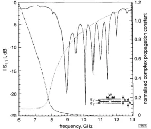
To understand the radiation characteristics of a microstrip LWA, we obtained its complex propagation constant p
+
ja in the leaky (radiation) region, where p is Ihe phase constant and a is the attenuation constant. We employed the rigorous (Wiener-Hop0 solutions of [7] to obtain the normalised complex propagation constant. 8 is the elevation angle between the main-beam direction and the end-fire direction, and it can be calculated using the approximation 8 = co~-~(p/k,). Fig. 2 shows the normalised com- plex propagation constant against frequency. The measured return loss IS,,1
of this antenna is also shown in Fig. 2. We found that the return loss is lower in the leaky region. For !3 k,, power will leak into a space wave in addition to the surface wave. According to this relationship, we can predict that the main beam position will be a function of the frequency.# . f
r . . . ...
Fig. 2 Normalised complex propagation constant and measured return
loss of' aperture-coupled microstrip L WA
h = 0.508mm, W = 12mm, E, = 2.2, lc,: free-space wavenumber
. .
.
pi;
d k ,
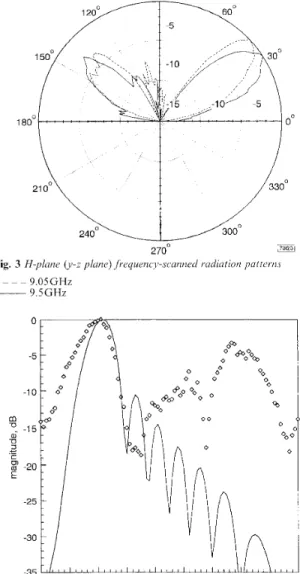
An NE42484C HEMT is used as the active element, and the drain is biased at 2.0V with a drain current of 1OmA. An Alpha DVG6064-I 1 varactor is used as the tuning element. By adjusting the DC bias of the varactor from I to 15V, the frequency of the VCO can be varied from 9.05 to 9.5GHz. The active aperture-cou- pled LWA can be tuned to obtain a beam-scanning angle of 10". Fig. 3 shows the meaourement resdtfi of the H-plane radiation patterns for operating ft-equencies at 9.05 and 9.5GHz. It shows that the main beam swings up from the end-fire direction (Z-axis) as the operating frequency decrease:;. The maximum effective iso- tropic radiated power (EIRP) of this antenna is -13.48
*
0.34dBm. As the frequency is varied, the variation in the imped- ance of the active aperture-fed LWA causes the difference inpower level. Fig. 4 shows the comparison of the theoretical and measured radiation patterns of this active aperture-coupled LWA at 9.05GH.z. The theoretical prediction of the radiation pattern is calculated by applying Huygen's principle at the far-zone field [8, 91. We can see these two patterns are reasonably similar.
goo
-
73613 ~
270' I
Fig. 3 H-plane ( J - z plane) jkequency-scanned radiation patteI:izs 9.05GHz
9.5GHr
- - - -
0 20 40 60 80 100 I20 140 160 180
e ,
deg 7mFig. 4 Theoretical and measuredjar field iadration putteins oj apcv f u ~ e- coupled leaky-wave antenna at 9 OSGHz
0
measured~ theory
Conclusion: An active aperture-coupled LWA has been described. The structure provides excellent shielding to eliminate the interfer- ence of the HEMT VCO and the antenna. This active antenna feeding structure is suitable for power combining techniques, active phase antenna array applications, modulated communica- tion links, radar, and otlicr microwavz and millimetre-wavz appli-
cations.
Acknowledgments: This work was supported by the National Science Council under grant NSC88-2213-El009-099.
0 IEE 1998
Electronics Letters Online No: 19981539
Nien-An Kao, Cheng-Chi Hu and C.F. Jou (Institute oj
Communication Engineering, National Chiao Tung University, Hsinchu,
Taiwan, Republic of China)
Jin-Jei Wu (Department of Electric Engineering, Kuo Yuan Institute of
Technology and Commerce, Luchu, Taiwan, Republic of China)
16 September 1998
References
'1 ORK. R 4 . \lARTI\EZ. R D . and CO\lPTO\ R C : 'Active par??: antenna element for arra? applications'. Eiec ~ 0 1 7 . Lett., 1990. 26. TSE\G. IY i . and C H L \ G . s J : '.\naI>sk and application of a c -
port apei-ture-coupled microstrip antenna-. IEEE 7 1 . ~ 1 7 ~ . , 1YYb.
MTT-46. pp. 530-535
POZER. D : ' A inici-ostrip antenna aperture coupled to a
microstripline'. Electron. Lctt., 1985, 21, pp. 49-50
JAX. B J . LEE 1- i(
.
MOON'. H w . YOON, Y.J., and PARK, I I . K : 'Anal) sis of finite-phased arrays of aperture-coupled stacked microstrip antennas'. IEEE Trans., 1997, AP-45, pp. 1201 -1204 MESZEL. I\ : 'A ne\+ traveling wave antenna in microstrip'. Proc. 8th European M i c r o \ v a x Conf.. 1978. pp. 3 0 2 ~ ~ 3 0 6H L . c c- . IYL J J . and JOL c F : 'An active ft-equency-tuned beam- scanning leak> -\\.a\ e antenna', Mic~roic. Opt. Technol. Lett., 1998, 17. pp. 43-45
O L I V E R A A . and LEE. K s : 'Microstrip leaky wave strip antennas'. 1986 IEEE AP-S Int. Symp. Dig., 1986. pp. 443-446
C H O U . G ~J . and T Z U A N G . c -K : 'Oscillator-type actixe-integrated antenna: The leaky-mode approach', I E E E T~:ans., 1996. MTT-44.
pp. 2265-2212
B ~ L A V I S . c 9 : 'Antenna theory analysis and design' (Wile). Ncn Yoi-k. 1982)
(7). pp. 4 9 4 4 9 5
Bandwidth enhancement of inset-
microstrip-line-fed equilateral-triangular
microstrip
antenna
Shyh-Tirng F a n g , Kin-Lu W o n g a n d Tzung-Wern Chiou
By embedding a pair of properly-bent narrow slots iii a n
equilateral-triangular microstrip patch, broadband operation of'
microstrip antennas with an inset microstrip-line feed can b?
achieved. With the proposed antenna design. the impxianci. baiidwidth can be as large as - 3.0 times that of a corresponding simple triangular microstrip antenna. Some simple design rules for the proposed antenna haye also been dctcrmiiied experimentally. The design rules and experimental results are presented and discussed.
Introduction: It has recently been shown that dual-frequency oper- ation can be obtained in a rectangular microstrip antenna with a pair of properly-bent narrow slots placed close to its patch edges; the two operating frequencies have the same polarisation planes and similar broadside radiation characteristics [ 11. Ratios of the two operating frequencies as low as -1.29 have also been obtained. It has been found in the present study that, by applying such a design technique to an equilateral-triangular microstrip patch, similar dual-frequency operation with an even lower frequency ratio can be obtained, which makes it possible for such a design to provide a wide operating bandwidth. In this Letter, suitable pai-ameters for the embedded bent slots for achieving broadband operation of the equilateral-triangular microstrip anteniia with an inset SOR microstrip-line feed (see Fig. 1) are experimentally stud- ied. Owing to the use of an inset microstrip-line feed, the pre- sented broadband antenna is suitable for applications in microstrip array designs and in integrating with coplanar micros- trip circuitry. Experimental results for the obtained broadband performance and sonic simple design rulcs dcteriniiicd Ti~om Lhc
present study are presented and discussed.
Antenna design and experinzental vesults: Fig. 1 shows the pro- posed broadband equilateral-triangular microstrip antenna with a pair of bent slots and an inset microstrip-line feed. The side length of the equilateral-triangular patch is d. The bent slots consist of two sections of narrow slots with a width of l m m and a bend angle of 150". The upper section of the bent slots (denoted here as slot 1) has a length