國立臺中教育大學資訊科學學系研究所碩士論文
工作流程排程方法中以縮減最長路徑
為原則之群聚方法研究
Critical Path Clustering Heuristics
for Workflow Scheduling
指導教授:黃國展 博士
研究生:古迪萱 撰
中華民國一百零一年六月
摘要
摘要
摘要
摘要
現今有許多大型的科學與工程應用系統都需要執行複雜且大量的計算及資料傳輸 工作,這些應用往往不只是由單一個程式組成的,而是由很多支程式共同合作來完成, 程式之間會互相傳遞資料,形成一個工作流程的結構。因此,工作流程的排程在高效能 計算環境中是很重要的研究議題,而群聚這類型的方法在工作流程排程方法中往往有較 好的結果,因為它可以降低工作之間的傳輸時間。 本篇論文中提出了三個新的工作群聚方法: 最長路徑群聚、最大邊群聚及關鍵子節 點群聚。所提出的新方法都是為了可以將動態關鍵路徑上工作之間的傳輸時間降低,以 提升工作流程執行的整體效能。為了評量不同群聚方法效能的優劣,我們以電腦模擬的 方式進行了一系列的實驗。實驗中,我們將提出的三個方法跟文獻中原本的路徑群聚方 法作效能的比較,結果證實我們所提出的新方法能夠有效進一步提升工作流程的執行效 能達 13%之多。 關鍵字 關鍵字關鍵字 關鍵字:::: 工作群聚、流程排程、動態關鍵路徑Abstract
Nowadays, many large-scale scientific and engineering applications are usually constructed as workflows due to large amounts of interrelated computation and communication, where different tasks within the workflow might execute distinct programs and have data or execution dependency among them.
Therefore, scheduling workflow efficiently is an important issue in HPC environments. Clustering is one of the major categories of workflow scheduling approaches, aiming at reducing inter-task communication costs. In this thesis, we propose three new clustering approaches, Critical Path Clustering Heuristic (CPCH), Selecting Larger Edge Based CPCH (SLECPCH), and Selecting Critical Child Based CPCH (SCCCPCH), which are expected to further improve the workflow execution performance by trying to minimize the communication costs along dynamic critical paths. The proposed schemes have been evaluated with a series of simulation experiments and compared to the Path Clustering Heuristic (PCH) scheme recently proposed in the literature. The performance results indicate that the proposed CPCH, SLECPCH, and SCCCPCH schemes outperform the previous PCH scheme significantly in terms of average makespan, up to 13% performance improvement.
Table of Contents
摘要 ... I Abstract ... II
Table of Contents ... III
List of Figures ... V
List of Tables ... VIII
Chapter 1 Introduction ... 1
Chapter 2 Related Work ... 5
Chapter 3 Path Clustering Heuristic ... 8
Chapter 4 Critical Path Oriented Clustering Approaches ... 13
4.1 Critical Path Clustering Heuristic ... 13
4.2 Selecting Larger Edge Based CPCH approach ... 16
4.3 Selecting Critical Child Based CPCH approach ... 19
Chapter 5 Simulation Environment ... 23
5.1 Major components ... 23
5.2 Classes in the simulator ... 24
Chapter 6 Performance Evaluation ... 31
6.2 Evaluation under Different Types of Fork-Join Structures ... 32
6.3 Evaluation under a Mixture of Various Fork-Join Structures ... 38
Chapter 7 Conclusions ... 44
List of Figures
Figure 1.1: An example of random DAG-based workflow ... 1
Figure 1.2: An example of fork-join DAG-based workflow ... 2
Figure 2.1: Comparison of workflow scheduling heuristics; (a) two example workflows; (b) list-based scheduling; (c) clustering-based scheduling; (d) duplication-based scheduling ... 6
Figure 3.1: PCH algorithm. ... 10
Figure 3.2: Example of PCH for single-level fork-join structure ... 11
Figure 3.3: Example of PCH for double-level fork-join structure ... 12
Figure 4.1: Example of CPCH for single-level fork-join structure ... 14
Figure 4.2: Example of CPCH for double-level fork-join structure ... 15
Figure 4.3: CPCH algorithm. ... 16
Figure 4.4: Example of SLECPCH for single-level fork-join structure ... 17
Figure 4.5: Example of SLECPCH for double-level fork-join structure ... 18
Figure 4.6: SLECPCH algorithm. ... 19
Figure 4.7: Example of SCCCPCH for single-level fork-join structure ... 20
Figure 4.8: Example of SCCCPCH for double-level fork-join structure ... 21
Figure 6.1: First type of workflows ... 33
Figure 6.2: Performance with the first type of workflows of single-level fork-join ... 33
Figure 6.3: Performance with the first type of workflows of double-level fork-join ... 34
Figure 6.4: Second type of workflows ... 34
Figure 6.5: Performance with the second type of workflows of single-level fork-join ... 35
Figure 6.6: Performance with the second type of workflows of double-level fork-join ... 35
Figure 6.7: Third type of workflows ... 36
Figure 6.8: Performance with the third type of workflows of single-level fork-join ... 36
Figure 6.9: Performance with the third type of workflows of double-level fork-join ... 37
Figure 6.10: Fourth type of workflows ... 37
Figure 6.11: Performance with the fourth type of workflows of single-level fork-join ... 38
Figure 6.12: Performance with the fourth type of workflows of double-level fork-join ... 38
Figure 6.13: Performance with a mixture of four different types of workflows of single-level fork-join ... 39
Figure 6.14: Performance with a mixture of four different types of workflows of double-level fork-join ... 40
Figure 6.15: Performance results with less resources for single-level fork-join structure ... 41
Figure 6.16: Performance results with less resources for double-level fork-join structure ... 41
... 42
Figure 6.18: Performance results for different CCR values for double-level fork-join structure ... 43
List of Tables
Table 5.1: Class definition of Dag_generator ... 25
Table 5.2: Class definition of Pch ... 27
Table 5.3: Class definition of Queuing_thread ... 28
Chapter 1 Introduction
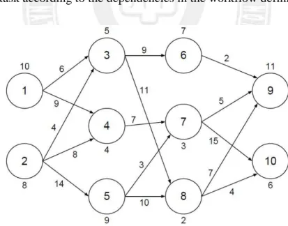
Nowadays, many large-scale scientific and engineering applications are usually constructed as workflows due to large amounts of interrelated computation and communication, where different tasks within the workflow might execute distinct programs and have data or execution dependency among them. Most workflow applications can be represented by Directed Acyclic Graphs (DAG) for describing inter-task dependencies [7]. Figure 1.1 is a workflow example of random DAG structure. Each node represents a task which executes a specific program. The number next to each node means the required execution time of the task. Each edge represents the inter-task dependency. The number next to an edge means the inter-task data transmission time. A workflow scheduler has to schedule and allocate each task according to the dependencies in the workflow definition.
Figure 1.1: An example of random DAG-based workflow
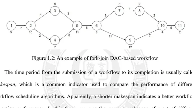
However, in practice, most workflow applications have more regular structures other than the random DAG in Figure 1.1. As discussed in [10][24], DAGs of fork-join structure are
a common type of infrastructure for many workflow applications. Figure 1.2 is an example of fork-join DAG-based workflows. Nodes like node 2 are called fork nodes and nodes like node 5 are called join nodes hereafter in this thesis. There are many workflow languages, such as YAWL [25] and BPEL [26], developed for programming fork-join based workflow applications. Accordingly, in this thesis we focus on the scheduling issues of fork-join DAG-based workflows.
Figure 1.2: An example of fork-join DAG-based workflow
The time period from the submission of a workflow to its completion is usually called makespan, which is a common indicator used to compare the performance of different workflow scheduling algorithms. Apparently, a shorter makespan indicates a better workflow execution performance. In this thesis, we use the average makespan of a set of different workflows to measure and compare the performance of various workflow scheduling algorithms under study.
Workflow scheduling in parallel and distributed environments, in general, is a NP-complete problem [11][12]. Therefore many heuristic methods have been proposed [2][3][6][7][8][9]. Heuristic-based workflow scheduling algorithms usually can be classified into three types: (1) list-based, (2) clustering-based, and (3) duplication-based. List-based heuristic approaches [16][17][18][21] first assign a priority to each task within a workflow and then schedule the tasks onto appropriate processors according to the decreasing order of
their priority values. Clustering-based approaches [5][10][13][14][15][19] aim to reduce the inter-task communication cost by scheduling a set of inter-dependent tasks onto the same processor. Duplication-based heuristic methods [20][22][23][27] duplicate a task on the set of processors where its successors run in order to avoid the inter-task communication costs. In this thesis, we focus on the clustering-based workflow scheduling approaches.
Among various clustering-based methods in the literature [5][10][13][14][15][19], Path Clustering Heuristic (PCH) is a recently proposed approach and has been shown to be effective in [10]. PCH was developed for dealing with fork-join based workflows. It partition a workflow of fork-join structure, e.g., Figure 1.2, into several task groups first, and then the list scheduling heuristic is applied to allocate these task groups onto processors. PCH finds a cluster by performing a depth-first search on the workflow until reaching a task ts which has a
non scheduled predecessor. The task ts that has a non scheduled predecessor is not included in
the current cluster. Therefore, a join node with several predecessors will always be clustered with the last predecessor reaching it. However, this kind of clustering approach doesn’t always minimize the communication cost for workflow execution. In this thesis, we propose three new clustering approaches, Critical Path Clustering Heuristic (CPCH), Selecting Larger Edge Based CPCH (SLECPCH), and Selecting Critical Child Based CPCH (SCCCPCH), which are expected to further improve the workflow execution performance by trying to minimize the communication costs along dynamic critical paths. The proposed clustering approaches were evaluated through a series of simulation experiments. Experimental results indicate that the proposed approaches outperform the previous PCH scheme significantly in terms of average makespan, up to 13% performance improvement.
on workflow scheduling, especially the clustering heuristics. Chapter 3 presents the previous PCH approach. Chapter 4 presents and discusses our CPCH, SLECPCH, and SCCCPCH approaches. Chapter 5 presents our simulation environment developed for conducting performance evaluation of the proposed methods. Chapter 6 evaluates and compares PCH and our three approaches through a series of simulation experiments. Chapter 7 concludes this thesis.
Chapter 2 Related Work
Heuristic-based workflow scheduling algorithms usually can be classified into three types: (1) list-based, (2) clustering-based, and (3) duplication-based. List-based heuristic approaches [16][17][18][21] maintain a list of all tasks within a workflow application according to their priorities and then schedule the tasks onto processors based on the list.
The main idea of clustering-based scheduling algorithms [5][13][14][15][19] is to reduce communication delay by grouping the tasks of heavy communication into the same cluster. In general, a clustering-based scheduling algorithm has three phases: (1) clustering, (2) merging, and (3) scheduling. In the clustering phase, the original workflow application is partitioned into clusters. The merging phase merges the clusters so that the remaining number of clusters equals to the number of resources. The scheduling phase then attributes start time of execution to each node.
Duplication-based heuristic methods [20][22][23][27] help a task to transmit the data to the resource of succeeding task(s) through duplicating the task on the destination processor. This duplication arrangement can reduce the communication cost from a task to a successor in order to minimize the overall makespan of the entire workflow.
Figure 2.1, is an example to illustrate and compare the above three kinds of workflow scheduling heuristics. In the example, list-based scheduling leads to the worst makespan due to it incurs large inter-task communication delay such as that between task B and task E. clustering-based scheduling performs the best as it can minimizes inter-task communication costs. Duplication-based scheduling does not perform as well as clustering-based scheduling although it also has the advantage of reducing inter-task communication costs. This is because
task duplication itself is a kind of overheads. Reduction of inter-task communication is achieved at the cost of increased computation workload. Although the overhead of task duplication would not hurt the makespan when scheduling a single workflow, it does degrade the performance of workflow execution when multiple workflows are running simultaneously as in the example Figure 2.1 (d). Since cluster-based workflow scheduling has the potential to perform better, in this thesis we focus on the study of clustering based approaches.
Figure 2.1: Comparison of workflow scheduling heuristics; (a) two example workflows; (b) list-based scheduling; (c) clustering-based scheduling; (d) duplication-based scheduling
Several workflow clustering approaches have been proposed in the literature [14]. Some previous approaches include linear clustering [28][29], single edge clustering [30][31], and list scheduling as clustering [15][19], and path clustering heuristic (PCH). The linear clustering algorithm [28][29] repeats to find the critical path among the tasks having not been
grouped by whole workflow. In linear clustering only dependent tasks are grouped into the same cluster [13][14]. The main part of the single edge clustering algorithm [30][31] sorts edges in decreasing order of their weights. The weights then become the priority of grouping. For each edge, the clustering algorithm checks if zeroing the edge would lead to a new schedule shorter or equal to the original schedule. If yes, the two clusters connected by this edge are merged into a single cluster. This clustering approach has higher time complexity. The list scheduling as clustering algorithm [15][19] is actually an adapted list scheduling approach. In each step of the algorithm, it deals with a node and considers all the edges pointing to that node for zeroing.
Recently, Path Clustering Heuristic (PCH) was proposed for scheduling fork-join DAG-based workflows and has been shown to be effective in [10]. PCH adopts a hybrid framework for workflow scheduling. At the first step a clustering scheme is used to partition a workflow into several task groups. Then, in the second step a list-based heuristic is applied to allocate these task groups onto processors. In this thesis, we adopt the same scheduling framework as PCH and develop several new task clustering schemes to further improve workflow execution performance.
Chapter 3 Path Clustering Heuristic
Since we adopt the scheduling framework of PCH [1][10] when developing our task clustering approaches, this chapter presents the PCH framework in details. First, we introduce some terminologies commonly used in discussing workflow scheduling. In this thesis, we focus on the workflows containing fork-join structures, which can be represented by a Directed Acyclic Graph (DAG), G (V, E, w, c), where:
V is the set of tasks, tn ∈ V, |V| = number of tasks;
E is the set of directed edges, en ∈ E, |E| = number of edges;
w is computation cost of task;
c is communication cost of edge.
Each workflow starts at one node, named the entry node, and finishes at one node, named the end node. Each node in the workflow is a task representing a specific job or program to execute and each edge represents the data dependence between two nodes. Each task starts its execution only after receiving all data from its parent nodes.
The following defines several node attributes which will be used in describing the workflow scheduling algorithms:
Computation cost :
, =
instructionsi : the amount of instructions in task i
powerr : processing power, in instructions per second.
Communication cost :
, =
,
ℎ .
ci,j: The communication cost between task i and j, using the link between
resource r and t. If r = t, ci,j = 0.
datai,j: the amount of data to be sent from task i to task j.
Priority :
succ(ni) : the set of immediate successors of task ti.
Earliest start time :
{
}
= pred k k k i EST r Time r Time r t EST ), ( max ) ( ) , (representing the earliest start time for execution of task i on resource k,
where Time(rk) is the earliest available time for resource rk and
EST = max"#∈ $"%&$EST'+ w'+ c',+& as defined in [1].
+ + = ∈maxsucc(n )( i,j j) t i i i w c P w P i j
, if i is the last task , otherwise
, if i =1 , otherwise
Estimated finish time : k i k i k i power ns instructio r t EST r t EFT( , )= ( , )+
representing the estimated finish time of task i on resource k.
The Path Clustering Heuristic (PCH) is a DAG scheduling heuristic which clusters the tasks into different groups and uses the list scheduling technique to schedule the tasks within a group onto the same resource. PCH focuses on reducing the communication costs between tasks and has been shown good performance in [1][4].
Algorithm 3.1 in the following shows how PCH partitions a workflow into a set of task groups. The clustering process starts with n, the unscheduled node with highest priority, as described at line 2. Line 3 includes the node n as the first node of the cluster. It then performs a depth-first search starting from node n until reaching a task which has a non scheduled predecessor, as described through line 4 to line 12. Line 13 returns the cluster found.
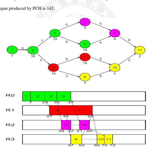
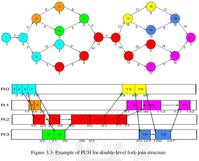
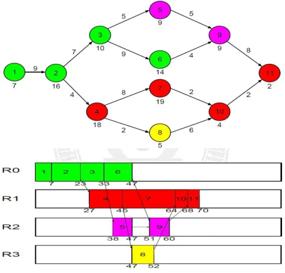
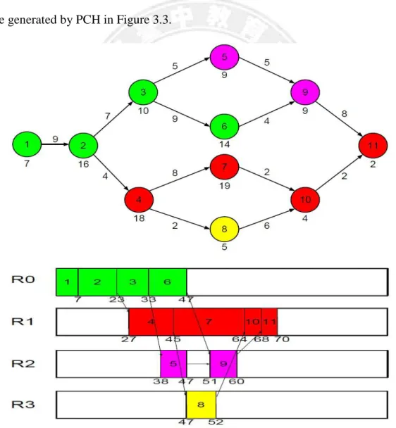
The PCH algorithm clusters tasks based on the node dependence in the workflow. Figure 3.2 is an example where PCH will generate 4 task groups: {1, 2, 3, and 6}, {4 and 7}, {5 and 9}, and {8, 10, and 11} first. Then, the computation cost of each task group can be computed based on the computation cost on each node within the group, and the communication cost between different task groups can be calculated according to the communication cost on each edge. After that PCH applies the list scheduling technique to allocate the task groups onto processors. The lower part of Figure 3.2 shows an example where PCH allocates the task groups onto 4 processors. The makespan for this workflow execution is 72. Figure 3.3 shows another example for PCH with a workflow of double-level fork-join structure. In this case, the makespan produced by PCH is 142.
Figure 3.3: Example of PCH for double-level fork-join structure
Looking at these two examples carefully, we can find that PCH does not always produce the best task clustering results. For example, in Figure 3.2, it might be better if node 10 and node 7 are put into the same cluster, since node 7 has a larger computation cost and is therefore on the critical path. Zeroing the communication cost between node 10 and node 7 can effectively shorten the length of critical path and hence reduce the makespan of the entire workflow. A similar situation occurs in Figure 3.3, where clustering nodes 16, 19, and 21 into the same cluster might produce a better schedule. The above observations motivated our work in this thesis to develop new task clustering schemes to further improve workflow execution performance.
Chapter 4 Critical Path Oriented Clustering
Approaches
This chapter presents three new workflow clustering approaches: Critical Path Clustering Heuristic (CPCH), Selecting Larger Edge Based CPCH (SLECPCH), and Selecting Critical Child Based CPCH (SCCCPCH), which were developed with the aim of reducing the length of dynamic critical path.
4.1 Critical Path Clustering Heuristic
Different clustering algorithms mainly differ in how they deal with the forking nodes and join nodes. The PCH algorithm [10] finds a cluster by performing a depth-first search on the workflow until a task which has a non scheduled predecessor. The task that has a non scheduled predecessor is not included in the current cluster. Therefore, a join node with several predecessors will always be clustered with the predecessor which is the last one to reach it. However, this kind of clustering approach doesn’t always minimize the communication cost for workflow execution and leads to a degraded performance. In the following, we propose a Critical Path Clustering Heuristic (CPCH) approach, which minimizes the inter-task communication cost by clustering a join node with the predecessor on the dynamic critical path.
Figure 4.1 is an example illustrating how CPCH works. Take node 10 for example, it would be clustered with node 8 using the PCH algorithm. However, since the critical path is {4, 7, and 10}, our CPCH chooses to cluster node 10 with node 7. Finally CPCH will generate
4 task groups: {1, 2, 3, and 6}, {4, 7, 10, and 11}, {5 and 9}, {8} and lead to a makespan of 70, shorter than the schedule produced by PCH in Figure 3.2. Figure 4.2 shows another example for CPCH with a workflow of double-level fork-join structure. In this case, the makespan produced by CPCH is 138, also shorter than the schedule generated by PCH in Figure 3.3.
Figure 4.2: Example of CPCH for double-level fork-join structure
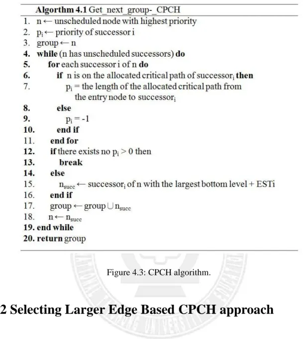
Algorithm 4.1 in the following describes the CPCH scheme in details. The clustering process starts with n, the unscheduled node with highest priority, as described at line 1. Lines 5 to 11 calculate the priority of each successor of n. For those successors whose allocated critical paths do not go through n, their priority values are set to -1 for excluding them from current cluster. If no successors’ critical path goes through n, the clustering process stops, as described at lines 12 to 14, and current cluster is returned at line 20. Otherwise, the successor with the highest priority value will be included in current cluster and the entire clustering process repeats to explore the successors of the new node, as described at lines 15 to 19.
Figure 4.3: CPCH algorithm.
4.2 Selecting Larger Edge Based CPCH approach
The above CPCH approach focuses on how to cluster join nodes and adopts the same clustering scheme as PCH to deal with fork nodes, where the child with the largest bottom level [14] plus earliest start time will be included into the cluster. Sometimes the child with the largest communication cost to the fork node will not be included into the cluster because it has a smaller bottom level [14]. In this section we present a new clustering approach, called Selecting Larger Edge Based CPCH (SLECPCH), which adopts a greedy method to deal with the fork node, always clustering the child with the largest communication cost and the fork
node together.
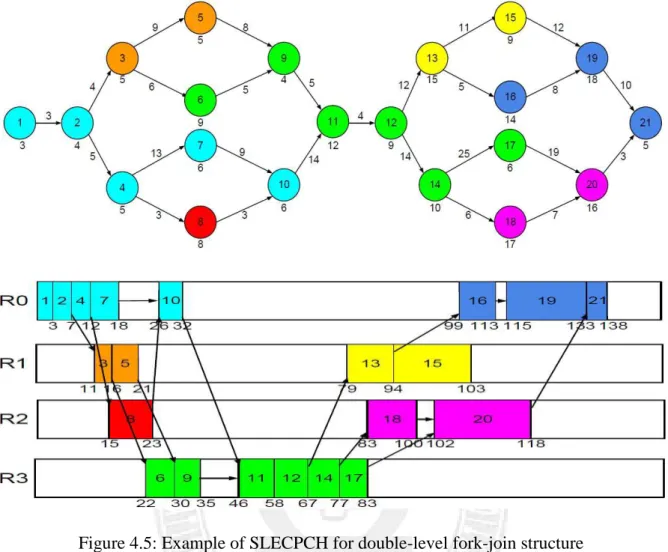
Figure 4.4 is an example illustrating how the SLECPCH scheme works. Take node 3 for example, it would be clustered with node 5 using PCH. However, since node 3 has a larger communication cost to node 6 than node 5, SLECPCH chooses to cluster node 3 with node 6. Finally SLECPCH will generate 4 task groups: {1, 2, 3, and 6}, {4, 7, 10, and 11}, {5 and 9}, {8} and lead to a makespan of 70, shorter than the schedule produced by PCH in Figure 3.2. Figure 4.5 shows another example for SLECPCH with a workflow of double-level fork-join structure. In this case, the makespan produced by SLECPCH is 138, also shorter than the schedule generated by PCH in Figure 3.3.
Figure 4.5: Example of SLECPCH for double-level fork-join structure
Algorithm 4.2 in the following describes the SLECPCH scheme in details. The clustering process starts with n, the unscheduled node with highest priority, as described at line 1. Lines 5 to 11 calculate the priority of each successor of n. For those successors whose allocated critical paths do not go through n, their priority values are set to -1 for excluding them from current cluster. If no successors’ critical path goes through n, the clustering process stops, as described at lines 12 to 14, and current cluster is returned at line 20. Otherwise, the successor with the largest communication cost will be included in the current cluster and the entire clustering process repeats to explore the successors of the new node, as described at lines 15 to 19.
Figure 4.6: SLECPCH algorithm.
4.3 Selecting Critical Child Based CPCH approach
This section presents another new clustering approach, called Selecting Critical Child Based CPCH (SCCCPCH), which tries to make a compromise between PCH and SLECPCH when dealing with the fork node. SCCCPCH takes not only the communication cost but also the computation cost into consideration when evaluating each child of the fork node. It clusters the fork node and the child with the largest communication cost plus computation cost together.
Figure 4.7 is an example illustrating how the SCCCPCH scheme works. Take node 2 for example, it would be clustered with node 3 in the SLECPCH algorithm because node 2 has a
larger communication cost to node 3 than node 4. On the other hand, node 2 would be clustered with node 4 using SCCCPCH since node 4 has a larger communication cost plus computation cost than node 3. Finally SCCCPCH will generate 4 task groups: {1, 2, 4, 7, and 10}, {3 and 6}, {5, 9, and 11}, {8} and lead to a makespan of 69, shorter than the schedule produced by SLECPCH in Figure 4.4. Figure 4.8 shows another example for SCCCPCH with a workflow of double-level fork-join structure. In this case, the makespan produced by SCCCPCH is 137, also shorter than the schedule generated by SLECPCH in Figure 4.5.
Figure 4.8: Example of SCCCPCH for double-level fork-join structure
Algorithm 4.3 in the following describes the SCCCPCH scheme in details. The clustering process starts with n, the unscheduled node with highest priority, as described at line 1. Lines 6 to 12 calculate the priority of each successor of n. For those successors whose allocated critical paths do not go through n, their priority values are set to -1 for excluding them from current cluster. If no successors’ critical path goes through n, the clustering process stops, as described at lines 13 to 15, and the current cluster is returned at line 21. Otherwise, the successor with the largest communication cost and computation cost will be included in the current cluster and the entire clustering process repeats to explore the successors of the new node, as described at lines 16 to 20.
Chapter 5 Simulation Environment
This chapter presents the software simulator we developed for conducting the performance evaluation of the proposed clustering-based workflow scheduling approaches. The simulator was developed based on the discrete-event simulation methodology. The entire simulation process is controlled by the function SimulationGO(). It controls what kind of DAGs to generate and determines the number of computing resources. Section 5.1 presents major components in the simulator and Section 5.2 presents the classes used to build the simulator.
5.1 Major components
The simulator has three major components used to represent workload, queuing mechanisms and computing environment, respectively.
Input Workload :
The workflows generated by the simulator conforms to the Directed Acyclic Graph (DAG) model, G (V, E, w, c), where V is the set of tasks, E is the set of directed edges, w is computation cost of task and c is communication cost of edge between two tasks. In the simulator, a DAG is represented by a linked-list data structure where each node may have multiple outgoing links to its successor nodes.
Queuing System :
There are two system queues in the simulator: waiting queue and ready queue. All tasks of the workflow will be put into the waiting queue upon its submission. As time
proceeds, task clusters will be moved into the ready queue waiting for scheduling when all its preceding tasks finish execution.
Computing Environment:
The computing resources are assumed to be homogeneous in various aspects, such as computing speed, memory size and hard disc size. The communication speed between any two machines is assumed to be the same. The costs include task computation cost and inter-task communication cost, which represent task execution time and data transfer time. If two tasks are allocated onto the same resource, the communication cost between them is set to zero.
5.2 Classes in the simulator
This section presents the major classes used to build the simulator, including Dag_generator, Pch, Queueing_thread and Simulation_thread.
Dag_generator :
Class Dag_generator is responsible for generating input workload. It can generate two types of workflows: random DAG workflows and fork-join DAG workflows as show in Figures 1.1 and 1.2, respectively. Table 5.1 shows the Dag_generator class in the UML style. It contains 9 attributes and 4 functions.
Table 5.1: Class definition of Dag_generator Dag_generator
+dagnum: int +dagstarttime: int +node: unsigned int +edge: unsigned int +prenode: LinkedList +sucnode: LinkedList +comptime: int +commtime: int +ccr: double Fork-join(int dagnum) General(int dagnum) node_generator() edge_generator() checkrankvalue(int dagnum) checkest(int dagnum)
The attributes and functions in Dag_generator are described as follows:
Attributes:
1. dagnum: the number of DAGs to be generated.
2. dagstarttime: representing the DAG submission time.
3. node: the number of tasks in DAG, a random number.
4. edge: the number of edges in DAG, a random number.
5. prenode: the predecessor nodes of each node.
6. sucnode: the successor nodes of each node.
8. commtime: the communication cost for each node, a random number.
9. ccr: communication cost to computation cost ratio.
Functions:
1. Fork-join(int dagnum): randomly generating a fork-join DAG. It first randomly determines the numbers of nodes and edges and then invokes node_generator() and edge_generator().
2. General(int dagnum): randomly generating a random DAG. It first randomly determines the numbers of nodes and edges and then invokes node_generator() and edge_generator().
3. node_generator( ): randomly generating the parameters of each node, such as computation cost and communication cost.
4. edge_generator( ): generating the inter-task dependency structure.
5. checkrankvalue(int dagnum): computing the bottom level [14] of each node.
6. checkest(int dagnum): computing the top level [14] of each node.
Pch :
Class Pch is responsible for clustering nodes within a DAG into a set of task clusters according to the inter-task dependency structure. Table 5.2 lists the members of the Pch class.
Table 5.2: Class definition of Pch Pch
+groupnum: unsigned int +pchnode: LinkedList +pch_starttime: unsigned int +pch_comptime: unsigned int +pch_overtime: unsigned int +pched: boolean
startpch(int dagnum)
groupparameter(int dagnum) checknode(int dag, int node) sortgroup(int dagnum)
The attributes and functions in Pch are described as follows:
Attributes:
1. groupnum: the number of task clusters within DAG.
2. pchnode: the nodes put into the task cluster.
3. pch_starttime: the start time of a task cluster, determined by the DAG’s start time and the task dependency involving the nodes within the cluster.
4. pch_comptime: the computation cost for each task cluster, calculated based on the computation cost of each task within the cluster.
5. pch_overtime: the end time of a task cluster, determined by the DAG’s start time and the task dependency structure involving the nodes within the cluster.
6. pched: indicating whether the node has been clustered into a task cluster or not.
Functions:
1. startpch(int dagnum): using the clustering heuristic approaches to process a DAG. It invokes groupparameter(int dagnum), checknode(int dag, int node), and sortgroup(int dagnum).
2. groupparameter(int dagnum): determining the values of the parameters of each task cluster, such as pchnode, pch_starttime, pch_comptime, and pch_overtime.
3. checknode(int dag, int node): checking whether the node is put into a task cluster or not.
4. sortgroup(int dagnum): sorting the task clusters of a DAG based on their start time and inter-task dependency.
Queueing_thread :
Class Queuing_thread is responsible for maintaining the queuing system. This class implements the dynamic scheduling mechanism and ready task queuing behavior in the simulator. Table 5.3 shows the members of the Queuing_thread class.
Table 5.3: Class definition of Queuing_thread Queuing_thread
+dagchecklist: LinkedList +groupchecked: unsigned int +queuelist: LinkedList +time: int
+priority: unsigned int
addintoqueuelist(int dag, int group, int priority)
Attributes:
1. dagchecklist: a list of DAGs to be checked for new ready task clusters.
2. groupchecked: the number of task clusters checked.
3. queuelist: the list including all ready task clusters.
4. time: the global system time.
5. priority: the priority for each task cluster based on the rank value of first task in a cluster.
Functions:
1. addintoqueuelist(int dag, int group, int priority): adding ready task clusters into the ready queue based on their priority values.
Simulation_thread :
Class Simulation_thread implements all the scheduling and allocation methods in this thesis. Table 5.4 shows the members of the Simulation_thread class.
Table 5.4: Class definition of Simulation_thread Simulation_thread
+resourcesnum: int +efficiency: double
+sim_starttime: unsigned int +sim_comptime: unsigned int +sim_overtime: unsigned int +simed: boolean
gap_search(int dag, int group)
Attributes:
1. resourcesnum: the number of computing resources.
2. efficiency: the computing speed of each resource.
3. sim_starttime: the start time for a task cluster allocated on a resource.
4. sim_comptime: the computation time for a task cluster allocated on a resource.
5. sim_overtime: the end time for a task cluster allocated on a resource.
6. simed: used to check whether a task cluster has been simulated or not.
Functions:
1. gap_search(int dag, int group): implementation of the continuous gap search heuristic [1].
Chapter 6 Performance Evaluation
This chapter presents a series of simulation experiments which evaluated the proposed workflow clustering approaches in terms of average makespan. We compare the proposed CPCH, SLECPCH, and SCCCPCH approaches with the original PCH scheme in [10].
6.1 Experimental setting
This section describes the experimental setting in our simulation studies including DAG generation, workload parameters and performance metrics.
We implemented a DAG generator to produce workflows of fork-join structures for the following simulation experiments. The DAG generator works as follows:
1. It generates a DAG with one entry node and one end node.
2. Each DAG contains three or six fork-join structures.
3. Each fork operation produces two branches.
4. Each branch contains one node.
5. It can generate DAG’s with different CCR values: 0.1, 1, and 10.
6. It assigns a random weight to each node and edge according to the specified CCR value.
The experiment setting is as follows:
1. The computing resources for executing the workflows are assumed to be a homogeneous system.
2. Each DAG might have 11 or 21 nodes.
3. Each node has the computation cost ranging from 1 to 30 seconds.
4. Each edge has the communication cost ranging from 1 to 45 seconds.
5. All DAG’s are assumed to be ready at time 0.
6. Each experiment was conducted for 100 times and the average performance value was calculated.
We used the average makespan of all executed workflows to evaluate different clustering approaches. measure good and bad of the workflow performance.
6.2 Evaluation under Different Types of Fork-Join
Structures
In this section we classify the workflows of fork-join structure into four types and evaluate the proposed clustering approaches under each type of workflows accordingly. Figure 6.1 is an example of the first type of workflows where the edges connecting to the fork node have larger communication costs than the edges pointing to the join node. Figure 6.2 and Figure 6.3 show the performance evaluation of the proposed clustering approaches with the first type of workflows. The performance was measured by the reduction of the average makespan of all workflows, compared to the PCH approach [10]. The experimental results indicate that the proposed CPCH, SLECPCH and SCCCPCH schemes outperforms PCH significantly, up to 3% performance improvement.
Figure
Figure 6.2: Performance with the first type of workflows of single 0 1 2 3 4 5 CPCH 4.18 P er fo rm a n ce i m p ro v em e n t in m a k es p a n
Figure 6.1: First type of workflows
Performance with the first type of workflows of single-level fork
CPCH SLECPCH SCCCPCH
4.18
1.75
2.53
Single-level fork-join
Figure 6.3: Performance with the first type of workf
Figure 6.4 is an example of the second type of workflows where the edges connecting to the join node have larger communication costs than the edges starting from the fork node.
Figure 6.5 and Figure 6.6 show the performance evaluation of the approaches with the second type of workflows.
proposed CPCH, SLECPCH and SCCCPCH schemes outperforms PCH significantly, up to
13% performance improvement
of workflows, compared to the first type of workflows.
Figure 7.1 7.2 7.3 7.4 7.5 7.6 7.7 7.8 CPCH P er fo rm a n ce i m p ro v em e n t in m a k es p a n
Double
Performance with the first type of workflows of double-level fork
Figure 6.4 is an example of the second type of workflows where the edges connecting to the join node have larger communication costs than the edges starting from the fork node.
6.5 and Figure 6.6 show the performance evaluation of the proposed approaches with the second type of workflows. The experimental results
SLECPCH and SCCCPCH schemes outperforms PCH significantly, up to ce improvement. A larger performance improvement is achieved with this type of workflows, compared to the first type of workflows.
Figure 6.4: Second type of workflows
CPCH SLECPCH SCCCPCH
7.45
7.33
7.74
Double
-level fork-join
level fork-join
Figure 6.4 is an example of the second type of workflows where the edges connecting to the join node have larger communication costs than the edges starting from the fork node. proposed clustering
results show that the
SLECPCH and SCCCPCH schemes outperforms PCH significantly, up to . A larger performance improvement is achieved with this type
Figure 6.5: Performance
Figure 6.6: Performance with the second type of workflows of double
Figure 6.7 shows an example of the third type of workflows where the edges on the upper path between the fork and join nodes have larger communication costs than the edges
on the lower path. Figure 6.8 and Figure 6.9 show the performance evaluation of the 0 2 4 6 8 10 12 14 16 CPCH 11.7 P er fo rm a n ce i m p ro v em e n t in m a k es p a n 0 5 10 15 20 25 30 35 40 CPCH 31.18 P er fo rm a n ce i m p ro v em e n t in m a k es p a n
Double
with the second type of workflows of single
-Performance with the second type of workflows of
double-Figure 6.7 shows an example of the third type of workflows where the edges on the upper path between the fork and join nodes have larger communication costs than the edges
6.8 and Figure 6.9 show the performance evaluation of the
CPCH SLECPCH SCCCPCH 11.7 14.14 12.68
Single-level fork-join
CPCH SLECPCH SCCCPCH 31.18 35.19 39.07Double
-level fork-join
-level fork-join
-level fork-join
Figure 6.7 shows an example of the third type of workflows where the edges on the upper path between the fork and join nodes have larger communication costs than the edges 6.8 and Figure 6.9 show the performance evaluation of the proposed
clustering approaches with the third type of workflows.
the proposed CPCH, SLECPCH and SCCCPCH schemes outperforms PCH significantly, up
to 12% performance improvement superiority of the three clustering
Figure
Figure 6.8: Performance with the third type of 0 2 4 6 8 10 12 14 16 18 CPCH 13.9 P er fo rm a n ce i m p ro v em e n t in m a k es p a n
clustering approaches with the third type of workflows. The experimental
SLECPCH and SCCCPCH schemes outperforms PCH significantly, up performance improvement. Unlike the previous two types of workfl
superiority of the three clustering approaching remains the same in these two figures.
Figure 6.7: Third type of workflows
Performance with the third type of workflows of single-level fork
CPCH SLECPCH SCCCPCH
13.9 14.12
17.97
Single-level fork-join
results indicate that
SLECPCH and SCCCPCH schemes outperforms PCH significantly, up . Unlike the previous two types of workflows, the relative
s the same in these two figures.
Figure 6.9: Performance with the third type of workflows of double
Finally, Figure 6.10 is an example of the fourth type of workflows where the edges on
the lower path between the fork and join nodes have larger communication costs than the
edges on the upper path. Figure
proposed clustering approaches with the fourth type of workflows.
indicate that the proposed CPCH,
significantly, up to 11% performance improvement
clustering approaching remain
Figure 24 25 26 27 28 29 30 CPCH 25.85 P er fo rm a n ce i m p ro v em e n t in m a k es p a n
Double
Performance with the third type of workflows of double-level fork
Finally, Figure 6.10 is an example of the fourth type of workflows where the edges on een the fork and join nodes have larger communication costs than the Figure 6.11 and Figure 6.12 show the performance evaluation of the clustering approaches with the fourth type of workflows. The experimental
that the proposed CPCH, SLECPCH and SCCCPCH schemes outperforms PCH
performance improvement. Again, the relative superiority of the three remains the same in these two figures.
Figure 6.10: Fourth type of workflows
CPCH SLECPCH SCCCPCH
25.85 26.02
29.24
Double
-level fork-join
level fork-join
Finally, Figure 6.10 is an example of the fourth type of workflows where the edges on een the fork and join nodes have larger communication costs than the 6.11 and Figure 6.12 show the performance evaluation of the experimental results
SLECPCH and SCCCPCH schemes outperforms PCH . Again, the relative superiority of the three
Figure 6.11: Performance with the fourth type of workflows of single
Figure 6.12: Performance with the fourth type of
6.3
Evaluation under a Mixture of Various Fork
Structures
In the following, we compare the four clustering approaches 0 2 4 6 8 10 12 14 16 CPCH P er fo rm a n ce i m p ro v em e n t in m a k es p a n 20 21 22 23 24 25 CPCH 22.03 P er fo rm a n ce i m p ro v em e n t in m a k es p a n
Double
Performance with the fourth type of workflows of
single-Performance with the fourth type of workflows of double
-Evaluation under a Mixture of Various Fork
In the following, we compare the four clustering approaches, PCH, CPCH, SLECPCH,
CPCH SLECPCH SCCCPCH 8.4 13.63 15.95
Single-level fork-join
CPCH SLECPCH SCCCPCH 22.03 22.51 24.12Double
-level fork-join
-level fork-join
-level fork-join
Evaluation under a Mixture of Various Fork
-Join
and SCCCPCH, with a mixture of the four different types of workflows presen
previous section. Figure 6.13 schemes proposed in this thesis
performance improvement. For both single
greedy-based SLECPCH scheme outperforms the other approaches.
Figure 6.13: Performance with a mixture of four different types of workflows of single
fork-join 0 1 2 3 4 5 6 7 8 9 10 CPCH 7.7 P er fo rm a n ce i m p ro v em e n t in m a k es p a n
and SCCCPCH, with a mixture of the four different types of workflows presen
and Figure 6.14 show the experimental results. All of the three in this thesis achieve better performance than the PCH scheme
For both single-level and double-level fork-join structures, the based SLECPCH scheme outperforms the other approaches.
Performance with a mixture of four different types of workflows of single
CPCH SLECPCH SCCCPCH
7.7
9.84
9.39
Single-level fork-join
and SCCCPCH, with a mixture of the four different types of workflows presented in the
show the experimental results. All of the three better performance than the PCH scheme, up to 11%
-join structures, the
Figure 6.14: Performance with a mixture of four different types of workflows of double
fork-join
In the above experiments, there are ten computing resources for executing the workflows. In the following, we experiment with situat
are less computing resources for processing the same set of workflows. Figure 6.15 shows the
performance results of single
-results indicate that as the system load increases our approaches perform worse than PCH. However, the situation becomes different when dealing with
Figure 6.16 shows such a case with only three computing resources. In this case, all the three proposed approaches outperform PCH significantly.
20 21 22 23 24 25 26 CPCH 21.92 P er fo rm a n ce i m p ro v em e n t in m a k es p a n
Double
Performance with a mixture of four different types of workflows of double
In the above experiments, there are ten computing resources for executing the workflows. In the following, we experiment with situations where the system is more crowded since there are less computing resources for processing the same set of workflows. Figure 6.15 shows the -level fork-join workflows running on only two resources. The as the system load increases our approaches perform worse than PCH. However, the situation becomes different when dealing with double-level fork
Figure 6.16 shows such a case with only three computing resources. In this case, all the three proposed approaches outperform PCH significantly.
SLECPCH SCCCPCH
21.92
25.25
24.36
Double
-level fork-join
Performance with a mixture of four different types of workflows of double-level
In the above experiments, there are ten computing resources for executing the workflows. ions where the system is more crowded since there are less computing resources for processing the same set of workflows. Figure 6.15 shows the running on only two resources. The as the system load increases our approaches perform worse than PCH. level fork-join workflows.
Figure 6.15: Performance results with less resources
Figure 6.16: Performance results with less resource
The following experiments with workflows of different CCR values: 0.1, 1, and 10. The performance results are shown in Figure 6.17 and Figure 6.18 for single
double-level fork-join structures, respectively. -4 -3 -2 -1 0 CPCH -3.24 P er fo rm a n ce i m p ro v em e n t in m a k es p a n 0 2 4 6 8 10 12 14 CPCH 9.52 P er fo rm a n ce i m p ro v em e n t in m a k es p a n
Double
Performance results with less resources for single-level fork
Performance results with less resources for double-level fork
The following experiments with workflows of different CCR values: 0.1, 1, and 10. The performance results are shown in Figure 6.17 and Figure 6.18 for single
join structures, respectively. As shown in Figure 6.1
CPCH SLECPCH SCCCPCH 3.24 -1.89 -0.08
Single-level fork-join
CPCH SLECPCH SCCCPCH 9.52 12.75 13.63Double
-level fork-join
level fork-join structure
level fork-join structure
The following experiments with workflows of different CCR values: 0.1, 1, and 10. The performance results are shown in Figure 6.17 and Figure 6.18 for single-level and
fork-join workflows, the performance the other hand, in Figure 6.1 might lead to larger performance
Figure 6.17: Performance results for different CCR values for single 0 2 4 6 8 10 12 14 16 18 0.1 13.95 16.01 17.68 P er fo rm a n ce i m p ro v em e n t in m a k es p a n
performanceimprovement decreases as the CCR value increases. On the other hand, in Figure 6.18, for double-level fork-join workflows, higher CCR values might lead to larger performance improvement.
Performance results for different CCR values for single-level fork
1 10 9.8 9.21 7 9.81 14.24 10.13 CCR
Single-level fork-join
improvement decreases as the CCR value increases. On join workflows, higher CCR values
level fork-join structure
CPCH SLECPCH SCCCPCH
Figure 6.18: Performance results for different CCR values for double 0 5 10 15 20 25 30 0.1 20.32 19.73 18.79 P er fo rm a n ce i m p ro v em e n t in m a k es p a n
Double
Performance results for different CCR values for double-level fork
1 10 23.99 19.21 23.18 21 25.66 26.38 CCR
Double
-level fork-join
level fork-join structure
CPCH SLECPCH SCCCPCH
Chapter 7 Conclusions
Many large-scale scientific and engineering applications are usually constructed as workflows due to complex and large amounts of computation and communication. Therefore, scheduling workflow efficiently is an important issue in high-performance computing environments. Clustering is one of the major approaches of workflow scheduling, aiming at reducing inter-task communication costs.
In this thesis, we propose three new task clustering approaches, Critical Path Clustering Heuristic (CPCH), Selecting Larger Edge Based CPCH (SLECPCH), and Selecting Critical Child Based CPCH (SCCCPCH), to scheduling fork-join based workflows in parallel systems. CPCH minimizes the inter-task communication cost by clustering a join node with the ancestor on its dynamic critical path. SLECPCH is a greedy approach and clusters a fork node with the child having the largest communication cost from it. SCCCPCH makes a compromise between Path Clustering Heuristic (PCH) [10] and SLECPCH by clustering a fork node with the child of the largest communication cost and computation cost.
The proposed clustering approaches have been evaluated with a series of simulation experiments and compared to PCH in [10]. The experimental results indicate that the proposed CPCH, SLECPCH and SCCCPCH schemes outperforms PCH significantly, up to 10%, 11%, and 13% performance improvement in terms of average makespan.
References
[1] L. F. Bittencourt and E. R. M. Madeira, “Towards the Scheduling of Multiple Workflows on Computational Grids,” Journal of grid computing vol. 8, no. 3, pp. 419-441, 2009.
[2] Y. K. Kwok and I. Ahmad, “Static Scheduling Algorithms for Allocating Directed Task Graphs to Multiprocessors,” Proceedings of ACM Computing Surveys, vol. 31, no. 4, pp. 406–471, 1999.
[3] T. L. Adam, K. M. Chandy, and J. R. Dickson, “A Comparison of List Schedules for Parallel Processing Systems,” Proceedings of Communications of the ACM vol 17 no. 12 pp. 685–690, 1974.
[4] L. F. Bittencourt and E. R. M. Madeira, “Fulfilling Task Dependence Gaps for Workflow Scheduling on Grids,” Proceedings of the 3rd IEEE International Conference on Signal-Image Technology and Internet Based Systems (SITIS), Dec 2007.
[5] J. Liou and M.A. Palis, “An Efficient Clustering Heuristic for Scheduling DAGs on Multiprocessors”, Proceedings of Symp. Parallel and Distributed Processing, 1996.
[6] L. F. Bittencourt, R. Sakellariou, and E. R. M. Madeira, “DAG Scheduling Using a Lookahead Variant of the Heterogeneous Earliest Finish Time Algorithm,” Proceedings of 18th Euromicro Conference on Parallel, Distributed and Network-based Processing, 2010.
[7] M. Wieczorek, R. Prodan, A. Hoheisel, M. Wieczorek, R. Prodan, and A. Hoheisel, “Taxonomies of the Multi-Criteria Grid Workflow Scheduling Problem,” Grid Middleware and Services, pp. 237-264, 2008.
[8] M. Rahman, R. Ranjan, and R. Buyya, “Cooperative and Decentralized Workflow Scheduling in Global Grids,” Proceedings of Future Generation Computer Systems vol. 26, pp. 753-768, 2010.
[9] F. Ding, R. Zhang, K. Ruan, J. Lin, and Z. Zhao, “A QoS-based Scheduling Approach for Complex Workflow Applications,” Proceedings of the Fifth Annual ChinaGrid Conference, 2010.
[10] L. F. Bittencourt and E.R.M. Madeira, “A Performance-Oriented Adaptive Scheduler for Dependent Tasks on Grids,” Proceedings of Concurrency and Computation: Practice and Experience, vol. 20, pp. 1029–1049, 2008.
[11] M. R. Gary and D.S. Johnson, Computers and Intractability: A Guide to the Theory of NP-Completeness, Publisher: W.H. Freeman and Company, vol 24, issue 1, pp. 90, 1979.
[12] J. D. Ullman, “NP-Complete Scheduling Problems”, Journal of Computer and Systems Sciences, vol. 10, pp. 384-393, 1975.
[13] S. J. Kim and J.C. Browne, “A General Approach to Mapping of Parallel Computation upon Multiprocessor Architectures”, Proceedings of Int’l Conf. Parallel Processing, vol. 2, pp. 1-8, 1988.
[14] O. Sinnen, Task Scheduling for Parallel Systems, Wiley-Interscience, 2007
[15] T. Yang and A. Gerasoulis, “DSC: Scheduling Parallel Tasks on an Unbounded Number of Processors”, Proceedings of IEEE Trans. Parallel and Distributed System, vol. 5, no. 9, pp. 951-967, Sep 1994.
[16] Y. Kwok and I. Ahmad, “Dynamic Critical-Path Scheduling: An Effective Technique for Allocation Task Graphs to Multi-processors”, Proceedings of IEEE Transactions on Parallel and Distributed Systems, vol. 7, no. 5, pp. 506-521, May 1996.
[17] G. C. Sih and E.A. Lee, “A Compile-Time Scheduling Heuristic for Interconnection-Constrained Heterogeneous Processor Architectures”, Proceedings of IEEE Transactions on Parallel and Distributed Systems, vol. 4, no. 2, pp. 175-186, Feb 1993.
[18] H. EI-Rewini and T.G. Lewis, “Scheduling Parallel Program Tasks onto Arbitrary Target Machines”, Journal of Parallel and Distributed Computing, vol. 9, pp. 138-153, 1990.
[19] M. Wu and D. Gajski, “Hypertool: A Programming Aid for Message Passing System”, Proceedings of IEEE Trans. Parallel and Distributed System, vol. 1, pp. 330-343, Jul 1990.
[20] G. Park, B. Shirazi, and J. Marquis, “DFRN: A New Approach for Duplication Based Scheduling for Distributed Memory Multi-processor Systems”, Proceedings of Int'l Conf. Parallel Processing, pp. 157-166, 1997.
[21] J.J. Hwang, Y.C. Chow, F.D. Anger, and C.Y. Lee, “Scheduling Precedence Graphs in Systems with Interprocessor Communication Cost”, Proceedings of SIAM J. Computing, vol. 18, no. 2, pp. 244-257, 1989.
[22] Y. Chung and S. Ranka, “Applications and Performance Analysis of a Compile-Time Optimization Approach for List Scheduling Algorithms on Distributed Memory Multiprocessors”, Proceedings of Supercomputing, pp. 512-521, Nov1992.
[23] B. Kruatrachue and T.G. Lewis, “Grain Size Determination for Parallel Processing”, Proceedings of IEEE software, pp. 23-32, Jan 2010.
[24] Instance of fork-join DAG, http://www.hudong.com/wiki/Workflow (2012.05.13)
[25] Yet Another Workflow Language (YAWL), http://en.wikipedia.org/wiki/YAWL
(2012.05.29)
[26] Business Process Execution Language (BPEL),
http://en.wikipedia.org/wiki/Business_Process_Execution_Language (2012.06.01)
[27] I. Ahmad and Y. Kwok, “A New Approach to Scheduling Parallel Programs Using Task Duplication”, Proceedings of Int'l Conf. Parallel Processing, vol. 2, pp. 47-51, 1994.
[28] A. Gerasoulis and T. Yang, “On the Granularity and Clustering of Directed Acyclic Task Graphs”, Proceedings of IEEETransactions on Parallel and Distributed Systems, 4(6):686-701, Jun 1993.
[29] S. Y. Kung, “VLSI Array Processors”, Proceedings of Information and System Sciences Series. Prentice Hall, 1988.
[30] V. Sarkar, “Partitionning and Scheduling Parallel Programs for Execution on Multiprocessors”, Journal of MIT Press, 1989.
[31] A. Gerasoulis and T. Yang, “A Comparison of Clustering Heuristics for Scheduling DAGs on Multiprocessors”, Journal of Parallel and Distributed Computing, 16(4):276-291, Dec 1992.