行政院國家科學委員會專題研究計畫 成果報告
子計畫四:無線正交分頻多重進接頻道使用技術研究及全系
統整合(2/2)
計畫類別: 整合型計畫 計畫編號: NSC93-2219-E-009-014- 執行期間: 93 年 08 月 01 日至 94 年 07 月 31 日 執行單位: 國立交通大學電子工程學系暨電子研究所 計畫主持人: 林大衛 計畫參與人員: 林郁男、吳俊榮、洪崑健、董景中、陳昱昇、陳汝芩、王治傑、 紀國偉、陳勇竹 報告類型: 完整報告 報告附件: 出席國際會議研究心得報告及發表論文 處理方式: 本計畫可公開查詢中 華 民 國 94 年 10 月 26 日
行政院國家科學委員會補助專題研究計畫成果報告
無線正交分頻多重進接頻道使用技術研究及全系統整合
(2/2)
Wireless OFDMA Channel Utilization Techniques Research and Full-System Integration
計畫編號:NSC 93-2219-E-009-014 執行期限:93 年 8 月 1 日至 94 年 7 月 31 日 主持人:林大衛 交通大學電子工程學系 教授 計畫參與人員:林郁男、吳俊榮、洪崑健、董景中、陳昱昇、陳汝芩、 王治傑、紀國偉、陳勇竹 交通大學電子工程學系 研究生
摘要
本計畫為一整合型計畫之子計畫,全期三年,分兩次核定。本年的計畫名稱雖標示 為 2/2,實為第二次核定之第二年,故為全期研究的第三年。在全期計畫中,最主要的工作是基於IEEE 802.16a 標準(現已為 IEEE 802.16-2004 所取代),研究正交分頻多 重進接(OFDMA)在作無線行動通訊服務之用時的傳收技術與其軟體實現。其中的軟體 實現工作主要係併用數位訊號處理器(DSP)及個人電腦來完成。此外亦對多載波調變、 盲目等化、與分碼多重進接技術,從事基礎性的研究。在本報告中,我們除了簡介計 畫緣由與目的外,並對我們在以下幾方面的研究與成果作較深入的討論,即:正交分 頻多工(OFDM)系列傳輸系統的通道估計技術,以及基於 IEEE 802.16a 之分時雙工 (TDD)正交分頻多重進接傳輸模式之下行與上行傳收系統之數位訊號處理器軟體實現 與整合。
關鍵詞:IEEE 802.16、IEEE 802.16a、正交分頻多重進接、正交分頻多工調變、時間 同步、頻率同步、通道估計、數位訊號處理器軟體實現、盲目等化、直接序列分碼多 重進接
Abstract
This subproject is a part of an integrated project whose whole term is three years, but has been approved in two “installments.” Although the designated numeral reference in the subproject title for the current year is 2/2, this is actually the second year of study in the second installment, thus the third year in the overall term. For the whole term of the subproject, the major work is to base on the IEEE 802.16a standard (now superseded by IEEE 802.16-2004) and research into the transceiving technologies, as well as their software implementation, for wireless mobile communication employing orthogonal frequency-division multiple access (OFDMA). Concerning the software implementation of the transceiving technologies, we primarily employ digital signal processors (DSPs) in conjunction with personal computers. In addition, the subproject also considers some fundamental issues concerning multicarrier modulation, blind equalization, and code-division multiple access (CDMA). In this report, besides introducing the motivation and purpose of the project, we also give a more in-depth discussion of the research and achievements in the following subject areas: channel estimation technology for orthogonal frequency-division multiplexing (OFDM) series of transmission systems, and the DSP software implementation and integration of downlink and uplink transception systems based on the time-division duplex (TDD) OFDMA transmission mode of the IEEE 802.16a.
Keywords: IEEE 802.16, IEEE 802.16a, Orthogonal Frequency-Division Multiple Access
(OFDMA), Orthogonal Frequency-Division Multiplexing (OFDM), Time Synchronization, Frequency Synchronization, Channel Estimation, Digital Signal Processor (DSP) Software Implementation, Blind Equalization, Direct-Sequence Code-Division Multiple Access (DS-CDMA)
目錄
Table of Contents
一、計畫簡介... 1
二、OFDM 之先進通道估計技術研究與結果 ... 2
A. Introduction ... 2
B. A Time-Domain Approach to Channel Estimation... 2
C. Estimation of Multipath Delays... 3
D. Simulation Results... 5
E. Conclusion ... 6
三、簡易之OFDM 下行通道估計方法與其 DSP 軟體實現之研究 ... 7
A. Techniques for Downlink Channel Estimation ... 7
B. DSP Implementation... 7
四、TDD OFDMA 下行傳收系統之 DSP 實現與整合... 11
A. Introduction ... 11
B. Downlink Synchronization Method... 12
1. Initial Synchronization ... 12
2. Normal Synchronization ... 13
C. DSP Implementation... 13
1. Modulation ... 14
2. Framing and Deframing ... 14
3. FFT and IFFT ... 14
4. Transmitter and Receiver Filtering... 14
5. Synchronization and Other Transceiver Functions ... 15
6. System Integration... 15
D. Conclusion... 17
五、TDD OFDMA 上行傳收系統之 DSP 實現與整合... 18
A. Introduction ... 18
B. Uplink Synchronization Technique ... 18
C. DSP Implementation... 19
1. Architecture of the Overall System and Profile of Implemented Software ... 19
2. Transmitter and Receiver Filtering... 20
3. Synchronization... 21 4. Other Functions ... 21 D. Conclusion... 21 六、參考文獻... 23 七、計畫成果自評... 25 可供推廣之研發成果資料表... 26
一、計畫簡介
本計畫為一整合型計畫之子計畫,全期三年。該整合型計畫一主要目標是基於IEEE
802.16a 標準,研究正交分頻多重進接(orthogonal frequency-division multiple access, OFDMA)在作無線行動通訊服務之用時的傳收技術,並將多項分項技術用數位訊號處 理器(DSP)作軟體實現。本子計畫負責其中若干項傳收技術之研究,並從事相關之 DSP 軟體實現與整合工作。此外,本子計畫亦對多載波調變、盲目等化、與分碼多重進接 技術,從事較基礎性的研究。整個計畫係分兩次核定,本年度之計畫為第二次核定之 第二年。因此,本年之子計畫名稱雖標示為2/2,實為全期計畫的第三年。IEEE 802.16a 標準現已整併入 IEEE 802.16-2004,且為後者所取代,但在本計畫的初期(2002 年), 連前者都還未定稿,正式出版是在本計畫第一年度進行中的2003 年!
IEEE 802.16a 標準容許分頻雙工(frequency-division duplexing, FDD)及分時雙工 (time-division duplexing, TDD)兩種雙工方式。鑒於未來的高速無線通訊很可能具有雙
向不對稱的傳輸率,我們考慮 TDD,並兼顧下行與上行(或稱下鏈與上鏈)兩方向傳輸
技術的研究。IEEE 802.16a 之 OFDMA 實體層(PHY layer)傳輸系統,在下行與上行二
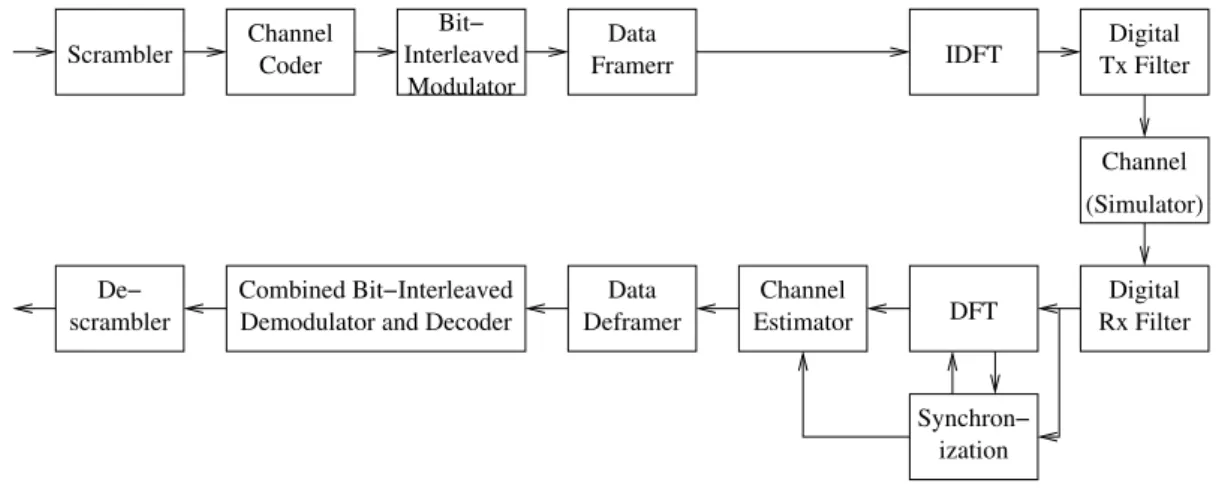
個方向的基本架構是相似的,概略如圖 1-1 所示。在前兩年的研究中,我們分別探討 了其中的通道編解碼、同步、通道估計、無線通道模擬、及一些相關的DSP 實現技術。 本年中,我們除了繼續通道估計演算法的研究外,並針對一些主要的下行與上行傳收 技術分別進行DSP 軟體實現,且予以整合。在軟體實現中,兩個關心的重點是軟體的 執行速率與效率。 以下我們分章簡述 OFDMA 方面的研究與成果。其中在第二章簡介我們所提出的
一個能處理任意的導引信號佈置(pilot allocation)並能在時變通道之下運作的 OFDM 通 道估計法[1]。在第三章中,我們簡介一組較簡單的通道估計方法,也是在 DSP 實現中 所使用的方法[2],[3]。在第四章及第五章中,我們分別介紹下行及上行傳收系統的 DSP 實現與整合[4]-[7]。此外,在盲目等化及分碼多重進接方面,我們也各有演算法及分 析上的成果,但不詳述於本報告中,請參[8]及[9]。 Bit− Interleaved Modulator ization Digital Tx Filter Digital Rx Filter Channel Estimator Channel (Simulator) IDFT DFT Data Framerr Data Deframer Channel Coder Scrambler Combined Bit−Interleaved Demodulator and Decoder De−
scrambler
Synchron−
二、
OFDM之先進通道估計技術研究與結果
1A. Introduction
Channel estimation is critical to the performance of coherent orthogonal frequency-division multiplexing (OFDM) demodulation, especially in transmission over time-varying wireless channels. Usually, known OFDM symbols or strategically placed pilots in the OFDM symbols are used to help the estimation.
After an initial estimation of the channel frequency response at the pilot locations, various methods can be used to estimate the channel response at other subcarrier locations. Two frequency-domain based approaches are minimum mean-square error (MMSE) estimation which employs Wiener filtering that exploits the channel correlation across subcarriers [10] and low-order polynomial interpolation between pilots [11]. The latter approach is simple and straightforward, but it encounters difficulty in systems employing wide pilot spacings (so that channel response may vary in a complicated manner between neighboring pilots). Indeed, MMSE estimation may also encounter a similar problem in this situation, because channel correlation may decrease with increasing subcarrier spacing. Only by exploiting the temporal correlation of channel response across successive OFDM symbols can these approaches address the difficulty, but then this requires that the channel be varying only slowly. Taking a different route, the time-domain approach [12] avoids the difficulty by estimating the time-domain channel response. Since the number of multipaths is usually much less than that of subcarriers, the number of unknown parameters is reduced. However, an essential piece of information is the set of path delays, which is not easy to acquire. In [13], an effective delay acquisition technique is developed, but with restriction on how pilots are spaced.
In this work, we also take the time-domain route, in which we try to estimate the multipath delays. The proposed method finds a set of delays which, together, minimizes the disparity between a subspace spanned by the estimated delays and that perceived at the pilot subcarriers. The method can handle the situations of fractional-sample-spaced multipath delays and arbitrary pilot allocation.
In what follows, Section B describes a time-domain approach to channel estimation assuming known multipath delays. Section C presents the proposed scheme for estimating the multipath delays. Section D reports some simulation results which illustrates the performance of the proposed scheme. And finally, Section E gives the conclusion.
B. A Time-Domain Approach to Channel Estimation
Consider OFDM transmission over a time-varying wireless channel. Let the OFDM system employ size-N DFT. Let there be P pilot subcarriers. Let x(i) denote the ith datum in
1 This chapter is mainly excerpted from C.-J. Wu and D. W. Lin, “Sparse channel estimation for OFDM
transmission based on representative subspace fitting,” in IEEE 61st
an OFDM symbol, where i = 0,1,…,N-1. Let there be L multipaths. And assume that the length of the cyclic prefix in the OFDM symbols is greater than the maximum possible multipath delay τmax.
If the coherence time of the channel is much larger than the OFDM symbol duration T, then the channel can be considered static over an OFDM symbol. Let y be the vector of received signal samples in one OFDM symbol after DFT, then
n h XW n g X y= + = +
where X = diag(x(0),x(1),…,x(N-1)), g is the vector of (sampled) channel frequency response, n is complex additive noise (assumed white Gaussian), W is an N x L matrix with its kth row given by 1/ N[e−j2πkτ0/T,...,e−j2πkτL−1/T]' with
l
τ , l = 0,1,…L-1, giving the delay of the lth path, and h = [h0,h1,…,hL-1]’ with hl, l = 0,1,…,L-1, giving the coefficient of
path l. Note that the columns of W are parametrized by τl and they span an L-dimensional subspace of the N-dimensional space. The subspace has thus been called the delay subspace [14]. The frequency-domain channel response g lies in the delay subspace.
Let S be the P×N selection matrix that selects the pilot locations of an N-vector. For example, y =Sy is the vector of received pilots and g =Sg is the vector of channel
frequency response at the pilot subcarrier locations. Thus we have n g X n h W X y= + = +
where X =SXS' and W =SW. The least-square (LS) estimations of g and h are then
given by y X
gˆ = −1 , hˆ=(W HW)−1W H gˆ,
respectively. Note that the number of pilots should be no less than that of paths, i.e., P≥L,
for a reasonable estimate via this formulation. From the above, the estimated impulse response vector hˆ gives a corresponding estimated channel frequency response vector as
y X W W W W h W gˆ = ˆ= ( H )−1 H −1 . (2-1)
In the right-hand side of (2-1), the only unknowns are the elements of W , which must
be estimated. As W is defined by the path delays, we now turn to their estimation, where
we let the pilot allocation be arbitrary.
C. Estimation of Multipath Delays
that approximates gˆ as closely as possible. We call the procedure representative subspace
fitting because the result is a subspace that represents gˆ in some way.
Assume proper synchronization so that we may let τ0 =0. At the ith iteration, one additional path delay τi is selected from the (τmax/s)floor possible values where s is the
chosen granularity in delay estimation. Thus we obtain L path delays after L-1 iterations. Actually, to determine L, we may simply iterate until the approximation error is satisfactory. To begin the procedure, construct an N×(τmax/s)floor matrix Wr where the lth column is a
vector of complex exponentials corresponding to the lth in the set of (τmax/s)floor delay values, and let Wr =SWr. Denote by Wr+1 the resulting estimate after the ith iteration
(l≤i≤L−1). Since τ0 =0, we initialize the procedure by letting W be the first column 1 of W . In the ith iteration, we select one column from r W and add it to r Wi as follows:
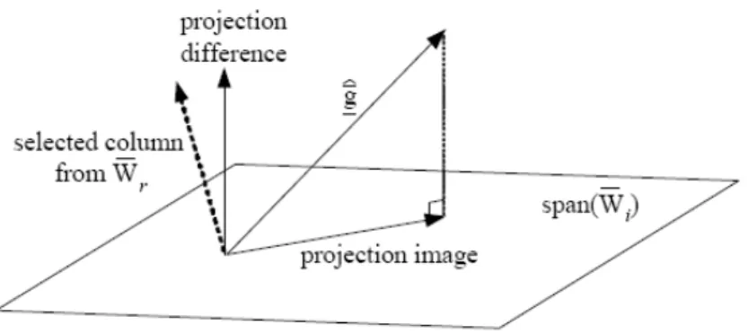
z Project gˆ onto the column span of Wi and obtain the difference pdi between gˆ
and the projection image. The difference is orthogonal to the column span of Wi.
z Find the column in W that has the maximum inner product with r . Add this
column to i d p i W to form Wi+1.
Fig. 2-1. The ith iteration: project gˆ onto the column span of Wi and select one column
from W to augment r Wi.
Fig. 2-1 is a conceptual illustration of the operation in the ith iteration. In each iteration i, since the column in W that has maximum inner product with r is selected to be added
i d
to Wi to form Wi+1, the magnitude of is reduced and the column span of 1 + i d p Wi+1 is
made closer to the delay subspace in a greedy fashion. Finally, W takes the position of L
W in solving for gˆ via (2-1).
D. Simulation Results
We simulate transmission over 4-path channels with maximum possible path delay τmax = 25 sample times. Each path gain is a complex Gaussian random variable. We let N = 256. Two different pilot numbers P = 12 and 24 are considered, where the pilot subcarriers are randomly located but are spread out so that they are not overly clustered together. The granularity s in delay search is set to 0.3. Two simple interpolation schemes, linear and spline, are also simulated for comparison.
Let the path delays be uniformly distributed in the range [0, τmax). The path gains are random but have the same variance. A Monte Carlo simulation is carried out where the path delays, the path gains, and the pilot locations vary from one OFDM symbol to another. Let each subcarrier employ QPSK.
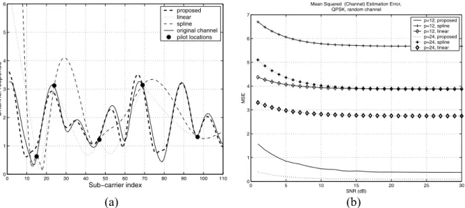
0 10 20 30 40 50 60 70 80 90 100 110 0 1 2 3 4 5 6 Sub−carrier index Channel response proposed linear spline original channel pilot locations 0 5 10 15 20 25 30 0 1 2 3 4 5 6 7
Mean Squared (Channel) Estimation Error, QPSK, random channel SNR (dB) MSE p=12, proposed p=12, spline p=12, linear p=24, proposed p=24, spline p=24, linear (a) (b) Fig. 2-2. Comparison of different channel estimation methods. (a) Estimated channel
frequency response (for a subset of subcarriers). (b) Mean-square estimation error at different pilot numbers, with L = 4.
Figure 2-2(a) shows the channel frequency responses estimated using the proposed method and the interpolation-based methods. For clarity, only a subset of the 256 subcarriers are shown. The black dots indicate the randomly chosen pilot locations in this OFDM symbol. Note that the proposed method has resulted in an estimate that is close to the actual channel response. Due to the wide pilot spacing, however, the two interpolation-based methods cannot capture the dynamics of channel variation between
pilots, and have thus failed to obtain good channel response estimates.
Figure 2-2(b) depicts the mean-square channel estimation errors of different channel estimation methods over all the OFDM symbols in the Monte Carlo simulation.
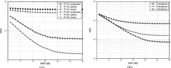
0 5 10 15 20 25 30 10−1 100 SNR (dB) SER P=12, proposed P=12, spline P=12, linear P=24, proposed P=24, spline P=24, linear 0 5 10 15 20 25 30 10−3 10−2 10−1 100 SNR (dB) SER 2 iterations 3 iterations 4 iterations (a) (b) Fig. 2-3. Average symbol error rates (SERs) at data subcarriers. (a) For different channel
estimation methods at different pilot numbers, with L = 4. (b) For the proposed algorithm at different numbers of iterations, with number of pilots = 24.
Figure 2-3(a) compares the symbol error rate (SER) performance of the different channel estimation methods. The proposed scheme clearly outperforms simple interpolation at all SNR levels. And the performance is better with more pilots, because then more data are available and used in aligning the representative subspace with the delay subspace.
Figure 2-3(b) shows the effect of iteration count in the proposed algorithm. As can be seen, setting the estimated number of paths to a value greater than L can be beneficial in the presence of noise. Therefore, the number of iterations may be determined from the performance requirement as well as computational complexity considerations. In any case, it is upper-bounded by P, because otherwise we would have an underdetermined set of equations for hˆ. The error floors in Fig. 2-3 at high SNR values are due to the spacing in
the multipath delays. When the multipaths are spaced apart, the error floors disappear. For more details, see [1].
E. Conclusion
We considered the time-domain approach to sparse multipath channel estimation for OFDM transmission and proposed a technique for the necessary multipath delay estimation. The proposed technique can handle arbitray pilot allocation and is particularly suitable for time-varying channels.
三、簡易之
OFDM下行通道估計方法與其DSP軟體實現之研究
2A. Techniques for Downlink Channel Estimation
Wideband mobile radio channels are usually frequency selective and time-variant. To aid channel estimation and signal reception, OFDM/OFDMA systems usually provide pilot subcarriers. This is the case with the IEEE 802.16a and the subsequent 802.16-2004 and 802.16e. We consider strictly non-blind, pilot-aided channel estimation methods which are simple and suitable for fixed-point digital signal processor (DSP) software implementation. Therefore, our estimation scheme basically contains the following components: channel estimation at pilot subcarriers, frequency-domain interpolation for channel response at non-pilot (i.e., data) subcarriers, and time-domain filtering to deal with channel variation.
The standard specifies two kinds of pilot: fixed-location ones and variable-location ones. There are 32 fixed-location pilots, which are unequally spaced in frequency. And there are nominally 142 variable-location pilots, whose carrier indices are given by 3L+12Pk, where
L is a kind of symbol index, cycling through the values 0, 2, 1, and 3 and taking one value every OFDM symbol, and . Eight of these locations coincide with the fixed ones, hence in actuality there are only 134 variable-location pilots.
} 141 ,..., 2 , 1 , 0 { ∈ k P
We employ simple least-square (LS) channel estimation at the pilot subcarriers [15], [16], which merely divides the received signal at each subcarrier by the known pilot value at that subcarrier to obtain the corresponding channel estimate. In our case, the division can even be avoided, because the pilot subcarriers are BPSK-modulated. After the LS channel estimation at the pilot subcarrier locations, we perform frequency-domain interpolation and time-domain filtering to obtain the response at non-pilot subcarrier locations as well as to reduce the noise effect in LS channel estimation. Several methods of interpolation and filtering are considered. They are, for frequency-domain interpolation, linear interpolation and second-order interpolation, and for time-domain filtering, two-dimensional (2D) interpolation and LMS adaptation. The techniques themselves and their performance as obtained from computer simulation are discussed in considerable detail in [2] and [3]. The simulation results show that linear interpolation in the frequency domain is about as good as second-order interpolation, and that 2D interpolation in the time domain is better than LMS adaptation. Hence we employ them in the DSP implementation. But in the following discussion we will present more in-depth information regarding linear interpolation.
B. DSP Implementation
We consider fixed-point DSP software implementation, where we employ Texas Instruments (TI)'s TMS320C6416 DSP. Its CPU contains eight parallel 32-bit function units,
2 This chapter is mainly excerpted from R.-C. Chen, D. W. Lin, and C.-J. Wu, “Pilot-aided channel estimation
for IEEE 802.16 OFDMA TDD downlink transmission and its DSP software implementation,” to appear in Proc. Workshop Consumer Electronics Signal Processing, Yunlin, Taiwan, ROC, Nov. 2005.
two of which are multipliers and the remaining six can do a number of arithmetic, logic, and memory access operations. There is also flexibility in arranging the data so that each function unit can do double 16-bit or quadruple 8-bit operations. Running at 600 MHz, the peak performance is 4800 MIPS.
TI supports a useful software development tool set with convenient graphical user interface (GUI), called the Code Composer Studio. It includes, among other things, a compiler, a debugger, and a profiler that can help the programmer analyze the efficiency of his/her code. The compiler supports several options to optimize the code either in size or in execution speed. In our case, code size is not a concern, but speed is. Hence we use -o3, the highest level (program level) of optimization. TI's library function also includes a set of “intrinsics,” which are C-callable functions mapped directly to assembly instructions that are not easily expressable in C. Examples of such intrinsics are functions for parallel loading of multiple data and parallel multiplications of multiple 16-bit data. We make use of some such intrinsics in our implementation.
Now we turn to the fixed-point DSP implementation. This entails careful conversion of the original program based on floating-point computation, used in simulation, to fixed-point.
Fig. 3-1. Structure of the implemented channel estimation system.
Figure 3-1 shows the structure of the implemented system. As far as channel estimation is concerned, the key function is Linear_Interp which does linear interpolation; other components only play a supporting role which are not the focus of this work (but are considered in greater depth in related studies such as [5]). The block Modulation (QPSK, 16-QAM, 64-QAM) maps binary data to the constellation points, Complex_Mul does complex multiplications to simulate the channel filtering effect, Pilot Location is the LS estimator which divides the received signal Y(f) at pilot locations by p = 4/3 or -4/3, Complex_Div is an equalizer which divides the received data signal by the estimated channel response, and De_Modulation maps the equalized signal into the constellation points as well as back into binary data. In a practical implementation, the functions Pilot
Location, Complex_Div, and De_Modulation should be re-designed for efficiency, e.g., by avoiding use of divisions and integrating with the subsequent error-control decoder. But in the present work they are left as is.
Table 3-1 lists the code sizes and the execution speed of Linear_Interp and some other function blocks in our final fixed-point implementation employing 16-bit computation, where “load” refers to the number of DSPs needed for real-time execution of the given function. Simulation shows that the 16-bit implementation performs similarly to the original floating-point program in noise performance. Enhancement of the implementation is being worked on. Reference [5] contains discussion on optimization of the modulation function.
It is of interest to see how efficient the software is relative to the DSP’s computing power and how the efficiency improves from using floating-point computation to using fixed-point computation. For fixed-point computation, the DSP can perform 6 32-bit additions and 2 32-bit multiplications per cycle, and 12 16-bit additions and 4 16-bit multiplications per cycle. For division, from measurement we see that it takes 22 and 21 cycles, respectively, in 32-bit and 16-bit fixed-point arithmetic. Now for Complex_Mul, each sample costs 4 real multiplications and 2 real additions, and for Complex_Div, each sample costs 6 real multiplications, 3 additions, and 2 divisions. Since a downlink OFDMA symbol contains 1702 used subcarriers (including pilots and data), the minimum cycle counts needed per symbol for Complex_Mul are roughly max{2/6,4/2}×1702 = 3404 and max{2/12,4/4}×1702 = 1702, respectively, with 32-bit and 16-bit fixed-point computation. That needed for Complex_Div are roughly (max{3/6,6/2}+2×22/2)×1702 = 42550 and (max{3/12,6/4}+2×21/2) 1702 = 38295, respectively, with 32-bit and 16-bit computation. ×
Table 3-1. Profile of Implemented Function Blocks Using 16-Bit Fixed-Point Computation
Function Code Size (Bytes) Load (# DSPs)
Complex_Mul 272 0.02
Linear_Interp 332 0.55
Complex_Div 428 1.15
De_Modulation 1068 1.05
Table 3-2. Comparison of Minimum Cycles and Actual Cycles Consumed per OFDMA Symbol Under Different Data Types for Various Functions
Function Type Actual Minimum Efficiency
float 899,231 3,404 0.38% 32-bit 15,338 3,404 22.19% A 16-bit 3,421 1,702 49.75% float 1,900,051 42,550 2.24% 32-bit 688,850 42,550 6.18% B 16-bit 162,960 38,295 23.50% float 467,233 12,852 2.75% 32-bit 441,423 26,082 5.91% C 16-bit 67,705 24,381 36.01%
Table 3-2 lists the efficiency figures, where for the floating-point implementation we have used the same minimum cycle counts as 32-bit fixed-point computation to gauge the efficiency, and the efficiency is defined as the ratio of minimum cycles needed to actual cycles consumed. We see that the efficiency is improved significantly from using floating-point computation to 32-bit and to 16-bit fixed-point computation.
Now consider Linear_Interp, wherein we use 567×8 additions, 567×4 multiplications, and 567×4 divisions per OFDMA symbol. Therefore, the minimum cycles are 26082 with 32-bit fixed-point computation and 24381 for 16-bit fixed-point computation. The efficiency is also listed in Table 3-2. The minimum cycles for floating-point computation are calculated on a different base, whose details are omitted here.
The implemented channel estimator can achieve real-time execution speed for the considered transmission bandwidth of 10 MHz. Improvement of the execution speed is possible, for example, by replacing the divisions with equivalent operations, and such work is part of the studies which are currently in progress. Indeed, part of the inefficiency in the final code is due to checks to prevent division by zero. This kind of conditional statements hamper the compiler’s ability in software pipelining. An enhanced version of the overall transceiver is currently being worked on.
四、
TDD OFDMA下行傳收系統之DSP實現與整合
3A. Introduction
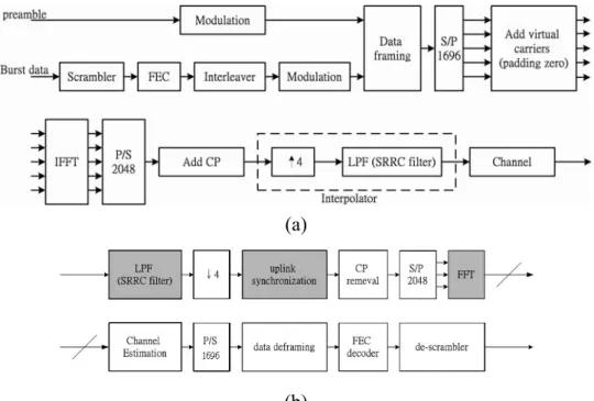
Figures 4-1 depicts the downlink (DL) transmitter and receiver structures. Not all blocks are treated to equal depth in this study. Some system parameters used in our study are listed in Table 4-1. We refer to the IEEE 802.16a and 802.16-2004 standards for detailed explanation of the parameters. Suffice it to say that the center frequency and the signal bandwidth are chosen arbitrarily but typical of some foreseeable applications.
modulation
carrier allocation Framing &
parameters: No_OFDM_symbol/ No_subchannel/ OFDM_symbol_offset/ Subchannel_offset
LPF (SRRC filter)
scrambler FEC modulationdata 1702
S/P add virtual carriers (padding zeros) burst 1 burst n channel D/A filter RF Tx pilot (preamble) DL_MAP,UL_MAP interpolator 4 burst n data burst 1 data 2048 P/S
IFFT add prefix
(fadding channel) (AWGN) not addressed in the
present study
(a)
(b)
Fig. 4-1. (a) DL transmitter structure. (b) DL receiver structure. (From [17].)
Table 4-1. System Parameters Used in This Study
Number of carriers (N) 2048
Center frequency 6 GHz
Signal bandwidth (BW) 10 MHz
Carrier spacing (Δf) 5.58 kHz
Sampling frequency (fs) 11.43 MHz
OFDM symbol time (Ts) 201.6 μs (2304 samples)
Cyclic prefix time (Tg) 22.4 μs (256 samples)
3 This chapter is mainly excerpted from Y.-S. Chen, D. W. Lin, and C.-J. Wu, “DSP Software Implementation
We have employed four-times oversampled square-root raised cosine (SRRC) transmitter and receiver filters, where the four-times oversampling is for convenience in simulating non-integer spaced multipath propagation. Both filters have the same length of 57 taps and the rolloff factor is set to 0.155 to satisfy the power mask specification [17].
In what follows, since synchronization is the most complicated function in this work, Section B introduces the downlink synchronization method. Section B discusses the DSP implementation. And Section D contains the conclusion.
B. Downlink Synchronization Method
In OFDM(A) transmission, several quantities need to be synchronized: the carrier frequency, the sampling clock, the (OFDM) symbol timing, and the (multi-symbol) frame timing. In this work, we omit the consideration of sampling clock synchronization for simplicity, which is equivalent to assuming that it is sufficiently accurate.
DL synchronization can be divided into two modes: the initial mode (or acquisition mode) for the initial establishment of a connection, and the normal mode (or tracking mode) for maintaining the synchronization. The reason for having a normal mode separate from the initial mode is to reduce the computational complexity in normal operation. Three kinds of quantity exist in the IEEE 802.16 specifications that can be used for synchronization: the guard interval (i.e., cyclic prefix), the pilot carriers (including the preamble), and the guard bands. We base our implementation on a modification of the methods in [17] and [18]. These methods have been designed with simplicity in mind. Not all the information available in the signal structure is exploited. However, reasonable performance is achieved.
1. Initial Synchronization
Our initial synchronization method consists of four stages, for symbol timing, fractional carrier frequency, integer carrier frequency, and frame timing, respectively.
In symbol synchronization (stage I), we do simple cyclic prefix (CP) correlation as | ) ( | max arg ˆ θ θ θ Γ = where
∑
+ − = + = Γ( ) L 1( ) *( ) k N k r k r θ θ θ ,with r(k) being the signal samples and L the CP length in number of samples. Since Γ(θ) has to be calculated for a series of values of θ, a way to further reduce the complexity is to employ the recursion
) ( ) ( ) ( ) ( ) ( ) 1 ( * * N L r L r N k r k r + + + + + − Γ = + Γθ θ θ θ .
The symbol timing obtained from (\ref{eq:max theta}) is refined in stage IV along with frame synchronization using pilot correlation.
In stage II, the fractional frequency offset εˆ , normalized to the carrier spacing used in the OFDM(A) transmission, is estimated using
) 2 /( ) ˆ ( ˆ θ π ε =−∠Γ .
That the frequency offset can be estimated in the above fashion is because a frequency offset ε results in an exponential modulation in the time domain by exp(j2πεk/N). From
this, we also see that integer values of ε cannot be estimated this way, because they yield phase offsets of integer multiples of 2π.
The integer frequency synchronization (stage III) is performed after fast Fourier transform (FFT). It is done by checking the power levels of the carriers in the guard bands and that of the two fixed pilot carriers at the edges of the used carriers. If the guard band carriers do not have low power or the two edge pilot carriers do not have high power, then we declare existence of integer frequency offset and attempt to correct it.
To determine the frame start time (stage IV), we correlate the received symbols (after FFT) with the pilots. In IEEE 802.16a, the DL symbols contain fixed-location pilots and varible-location pilots whose locations change from symbol to symbol. There are a total of 7 possible pilot structures. In our algorithm, a frame is determined to start if three successive DL symbols all have the maximum correlation with the preamble symbols' pilot structures (as compared to the other pilot structures).
After establishing the initial synchronization, we turn to normal operation. However, if 6 unexpected pilot patterns are encountered in a DL subframe, then we declare synchronization failure and revert to initial frame synchronization.
The performance of the correlation-based frame synchronization depends on the accuracy of symbol synchronization. Since the result of stage I may be subject to error, we refine the symbol timing estimate in the current stage by checking an additional range of sample locations centered at the location found in stage I. To reduce the computational complexity, the conventional FFT is only applied at location -32. At subsequent sample locations, the DFT may be computed recursively as
32 ± ) / 2 exp( )] ( ) ( ) ( [ ) (n X 1 n r k N r k j n N Xk = k− − − + π
where k is the location number and n is the carrier index.
2. Normal Synchronization
After initial synchronization, the subscriber station (SS) can obtain the frame duration from the DL signal and predict the next frame start time. Hence we only need to track minor timing and frequency variations. Methods used in stages I and II of initial synchronization can be used for this purpose. For added robustness, the pilot correlation of stage IV can also be used to determine the symbol timing more accurately. For this we use a reduced search window of ±16 samples, instead of the ±32 of initial synchronization.
We consider DSP software implementation of some key DL transceiver functions. The DSP employed is Texas Instruments (TI)'s TMS320C6416. It runs at 600 MHz and its CPU contains eight parallel 32-bit function units, of which six can do a variety of arithmetic, logical, or memory access operations and two can do multiplications. Besides 32-bit operations, they can also do dual 16-bit or quad 8-bit operations.
Since 32-bit operations are usually an overkill but 8-bit ones do not have sufficient accuracy for some functions, we decide to employ largely 16-bit operations, all fixed-point. Besides the choice of data formats, the techniques used for program efficiency include software pipelining, loop unrolling, loop partition, and good coding styles (proper program structure to reduce unnecessary operations). TI's Code Composer Studio provides a convenient development environment for code analysis and improvement.
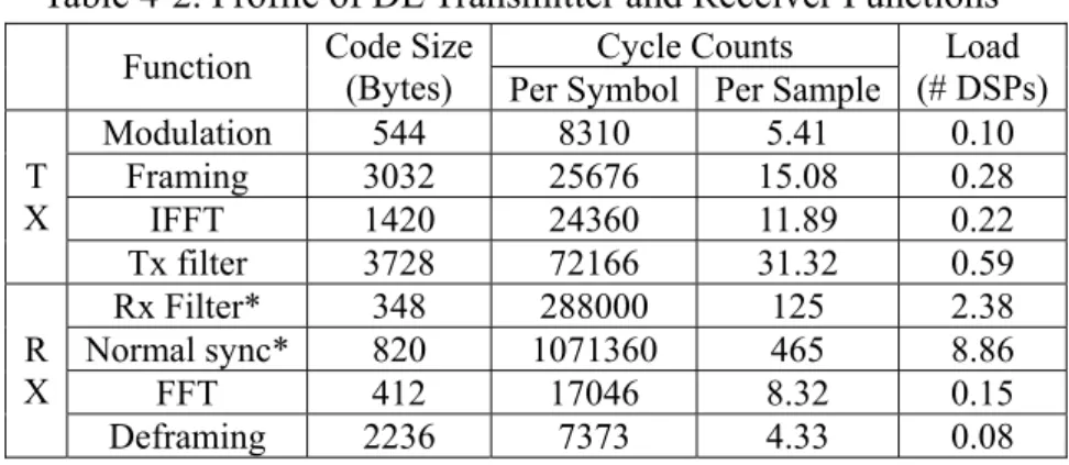
Below we first discuss the implementation of individual transceiver functions and then discuss their integration. The code sizes and cycle counts of various functions are summarized in Table 4-2, where “load (# DSPs)” gives the fraction of a single DSP’s computing power needed in real-time execution.
1. Modulation
There are three modulation options: QPSK, 16QAM, and 64QAM. We separate them into three functions and each of them is written in a way facilitating efficiency in the compiled code.
2. Framing and Deframing
The framing function places null values, pilots, and modulated data in their assigned carrier locations. The presence of variable-location pilots requires some attention in style of coding. An unsophisticated coding style employing many conditional branches can be detrimental to the execution speed. We use table-lookups to implement the framing and the deframing functions.
3. FFT and IFFT
The 16-bit FFT function that we use is taken from TI’s DSPLIB [19]. Since no 16-bit inverse FFT (IFFT) is provided, we build our IFFT function based on the FFT function. Hence the IFFT is somewhat less efficient than the FFT in code size and execution speed.
It is of interest to see how efficient the FFT function is in terms of CPU usage. A little analysis reveals that the mixed-radix algorithm employed requires 19974 real multiplications and 68102 real additions for 2048-point FFT. Since the DSP can do up to 4 16-bit real multiplications and 12 real additions per cycle, the minimum cycles needed, excluding data moves, are given by max{19974/4,68102/12} = 5676. From this point of view, the efficiency of the FFT function is approximately 33.3%.
Some discussion on good coding style for the transmitter SRRC filter is given in [7]. One particular technique employed to facilitate efficiency is the use of some “intrinsic functions” provided by TI for moving of multi-byte data between memory and CPU, where “intrinsic functions” are C-callable functions which are mapped to simple assembly instructions that are not easy to express in regular C instructions efficiently. Two of the functions are “_amemd8” and “_amemd8_const” which do aligned loads and stores of 8 bytes in single instruction.
Note in Table 4-2 that the relative inefficiency of the receiver filter is worse than the transmitter filter. This is one function where further work on of efficiency is envisioned.
5. Synchronization and Other Transceiver Functions
The synchronization function is implemented based on an earlier work [18] which already makes use of intrinsics, circular buffering, loop unrolling, and other techniques for execution efficiency. By modifying the setting of the compiler, we find that some gains in speed can be achieved. Since initial synchronization is a one-time function, we only show the code size and cycle counts for normal synchronization in Table 4-2. Further work on improving the synchronization function’s execution efficiency is envisioned.
Other important transceiver functions in the physical layer are channel estimation and error-control encoding and decoding-demodulation. Work on them is reported in the last chapter and in [3], [20], [21].
Table 4-2. Profile of DL Transmitter and Receiver Functions
Cycle Counts
Function Code Size
(Bytes) Per Symbol Per Sample
Load (# DSPs) Modulation 544 8310 5.41 0.10 Framing 3032 25676 15.08 0.28 IFFT 1420 24360 11.89 0.22 T X Tx filter 3728 72166 31.32 0.59 Rx Filter* 348 288000 125 2.38 Normal sync* 820 1071360 465 8.86 FFT 412 17046 8.32 0.15 R X Deframing 2236 7373 4.33 0.08 *Functions not yet well optimized.
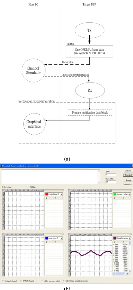
6. System Integration
We integrate the transmitter and receiver functions into a system as illustrated in Fig. 4-2(a), where the channel simulator on the PC can simulate multipath propagation, AWGN, and carrier frequency offset. A not yet fully optimized channel estimator employing “2-D interpolation” [3] and a simple unoptimized demodulation function are also integrated into the system to facilitate demonstration of system functions. A graphical user interface (GUI) is developed to facilitate control of execution and dynamic display of results, as shown in Fig. 4-2(b).
(a)
(b)
D. Conclusion
We presented a study on DSP software implementation of the physical-layer downlink transmitter and receiver functions under the TDD OFDMA mode of the IEEE 802.16 standards. Taken together, the not yet fully optimized code required the computing power of multiple DSPs to perform all the transmitter and receiver functions. We integrated the functions and attached a GUI for convenience in execution control and dynamic display of results. The system integration gave rise to additional execution overhead. Further improvement of the software efficiency is planned.
五、
TDD OFDMA上行傳收系統之DSP實現與整合
4A. Introduction
Figure 5-1 shows the structures of the uplink (UL) transmitter and receiver. Concerning the channel estimator, for simplicity, in the present DSP implementation we merely fake the existence of a channel estimator by assuming perfect knowledge of the channel response at the receiver. A space is reserved in the program structure for expanding it into a full-fledged channel estimator. Some system parameters used in our study have been listed in Table 4-1.
(a)
(b)
Fig. 5-1. (a) UL transmitter structure. (b) UL receiver structure.
In what follows, we briefly describe the uplink synchronization technique in Section B. Section C describes the DSP implementation, which employs the same platform as described in the last chapter. And Section D is a conclusion.
B. Uplink Synchronization Technique
In IEEE 802.16a, each TDD frame consists of a downlink (DL) subframe and a UL subframe. The first symbol in the UL subframe is an all-pilot preamble where the subscriber station (SS) should send on all its allocated subcarriers. The number of UL symbols following the preamble must be an integer multiple of 3.
For synchronization, we assume that after a successful initial synchronization and ranging, the UL transmission from an SS has the low frequency offset specified in the
4 This chapter is mainly excerpted from C.-C. Tung, D. W. Lin, and C.-J. Wu, “Software implementation and
integration of IEEE 802.16 OFDMA-TDD-mode uplink transceiver functions on digital signal processor,” to appear in Proc. Workshop Consumer Electronics Signal Processing, Yunlin, Taiwan, ROC, Nov. 2005.
standard. Hence no frequency synchronization is done in normal UL transmission. Acknowledgeably, while this assumption appears appropriate for fixed base station (BS) and SS, it is certainly debatable for mobile communication. Hence future enhancement of the implementation will add UL frequency synchronization. But for simplicity we leave it out in the present implementation.
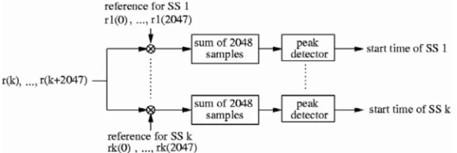
Since, according to the standard, the UL transmissions from different users may be offset by up to 50% of the minimum CP length, symbol timing synchronization is needed in the UL direction. Since the first symbol in an UL subframe consists of the all-pilot preambles transmitted by all users and the BS knows what each user transmits, for each user the BS can generate the same signal as this user's associated preamble and correlate the generated signal with the received signal over a range of successive sample positions to determine the peak location and take it as the symbol timing for this user. Figure 5-2 illustrates how this method works. We have over-designed the system to examine more than 50% of the minimum CP length for symbol timing synchronization. From all the peak locations (each corresponding to a particular user), we also find the earliest one, as this time is an important parameter for good signal reception [17]. (The proposed UL synchronization method has reduced complexity compared to the earlier proposal in [17].)
Fig. 5-2. UL synchronization method.
C. DSP Implementation
1. Architecture of the Overall System and Profile of Implemented Software
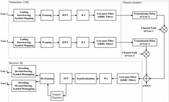
Figure 5-3 shows the overall structure of the implemented UL transmission system. There is one receiver (at the BS). For illustration purpose, we show two transmitters (at two SSs). The channel simulation is done in the host PC. We also develop a graphical user interface (GUI) on the PC for convenience in execution control and display of results.
For efficiency, we employ 16-bit fixed-point computations, which is accurate enough. Care is taken to properly position the binary point in each transceiver function to curtail overflow probability and obtain desirable performance. Table 5-1 gives the profile of the implemented transmitter and receiver functions. As in the last chapter, “load (# DSPs)” gives the fraction of real-time DSP computing power consumed in each function.
Fig. 5-3. Overall structure of implemented system.
Table 5-1. Profile of UL Transmitter and Receiver Functions
Function Code Size
(Bytes) Avg. Cycles per Sample Load (# DSPs) QPSK mod. 780 2.6 0.045 16QAM mod. 364 2.84 0.054 64QAM mod. 280 2.88 0.055 Framing 1812 11.04 0.21 IFFT 1180 11.79 0.22 T X Tx SRRC 2576 31.34 0.60 Rx SRRC 400 242 4.61 Deframing 784 10.85 0.21
Sync. 1020 Variable Variable
R X
FFT 412 7.40 0.14
2. Transmitter and Receiver Filtering
We implement the transmitter filter in the well-known polyphase form as shown in Fig. 5-4, where L = 4. Since we do block-based processing, which essentially filters each OFDM symbol separately, special care is taken in filtering of the boundary samples to avoid use of many if-else instructions so as to achieve execution efficiency.
It is of interest to compare our implementation with straightforward application of the FIR filtering function DSP_fir_gen() in TI's DSPLIB. It turns out that our implementation requires only 72209 clock cycles per OFDM symbol whereas using the library function requires roughly twice, 146372 cycles.
Fig. 5-4. SRRC transmitter filter in polyphase decomposition form [17].
To see the efficiency in CPU utilization of our implementation, since there are 2304 complex-valued samples to an OFDM symbol and 57 real-valued taps in the filter, the number of real multiplications for each symbol is given by (approximately) 2304×57×2 = 262656 and the number of real additions by (approximately) 2304×53×2 = 244224. The DSP can do four 16×16 multiplications and six 32×32 additions per cycle. Hence the minimum number of cycles needed is approximately max(262656/4,244224/6) = 65664. Thus our 72209 cycles yields a 91% efficiency.
The receiver filter is not yet well optimized, as can be seen from Table 5-1. It is one subject of future work to enhance the receiver filter’s efficiency.
3. Synchronization
For efficiency in implementation of the synchronization function, we use intrinsics to let the DSP load data in 64-bit units. Our aim is to let the DSP access eight 16-bit values every clock cycle so as to be able to do four 16×16 multiplies every clock cycle. An analysis of the number of arithmetic operations needed (in a similar spirit as the calculations shown in the last subsection) results in a minimum requirement of 1679360 cycles per user per frame. The implementation gives 1955700 cycles. Hence the efficiency is approximately 86%.
This amount of complexity is approximately 37251 times the DSP cycles available in a sample according to the system parameters given in Table 4-1. How exacting it is to a real-time implementation depends on how long a TDD frame is, since the latter is a design variable. In any case, it is desirable to improve the computational algorithm to reduce the complexity, and this is one subject for potential future work.
4. Other Functions
Some details of modulation, framing and deframing, and FFT and IFFT have been discussed in the last chapter. For FEC, as mentioned, we use the encoder and decoder of [20], whose functionality is being further improved.
D. Conclusion
functions under the OFDMA TDD mode of transmission of the IEEE 802.16 standards. For efficiency and practicality, the functions were implemented using fixed-point computation. Some of the functions achieved relatively high efficiency in CPU utilization. A GUI on the PC was also developed for convenience in execution control and display of results. At present, the not yet fully optimized code requires the computing power of some number of DSP chips to perform all the transmitter and receiver functions.
Several areas of the implementation that need improvement have been identified and are either being worked on or considered as potential future work.
六、參考文獻
[1] C.-J. Wu and D. W. Lin, “Sparse channel estimation for OFDM transmission based on representative subspace fitting,” in IEEE 61st
Veh. Technol. Conf., May 2005.
[2] R.-C. Chen, D. W. Lin, and C.-J. Wu, “Pilot-aided channel estimation for IEEE 802.16 OFDMA TDD downlink transmission and its DSP software implementation,” to appear in Proc. Workshop Consumer Electronics Signal Processing, Yunlin, Taiwan, ROC, Nov. 2005.
[3] R.-C. Chen, “IEEE 802.16a TDD OFDMA downlink pilot-symbol-aided channel estimation: techniques and DSP software implementation,” M.S. thesis, Dept. Electronics Engineering, National Chiao Tung University, June 2005.
[4] Y.-S. Chen, D. W. Lin, and C.-J. Wu, “DSP Software Implementation and Integration of IEEE
802.16 TDD-OFDMA-mode downlink transceiver functions,” to appear in Proc. Int.
Symp. Commun., Kaohsiung, Taiwan, ROC, Nov. 2005.
[5] Y.-S. Chen, “DSP software implementation and integration of IEEE 802.16a TDD OFDMA downlink transceiver system,” M.S. thesis, Dept. Electronics Engineering, National Chiao Tung University, Hsinchu, Taiwan, R.O.C., June 2005.
[6] C.-C. Tung, D. W. Lin, and C.-J. Wu, “Software implementation and integration of IEEE 802.16 OFDMA-TDD-mode uplink transceiver functions on digital signal processor,” to appear in Proc. Workshop Consumer Electronics Signal Processing, Yunlin, Taiwan, ROC, Nov. 2005.
[7] C.-C. Tung, “IEEE 802.16a OFDMA TDD uplink transceiver system integration and optimization on DSP platform,” M.S. thesis, Dept. Electronics Engineering, National Chiao Tung University, Hsinchu, Taiwan, R.O.C., June 2005.
[8] K.-C. Hung and D. W. Lin, “A hybrid variable step-size adaptive blind equalization algorithm for QAM signals,” to appear in Conf. Rec., IEEE Global Telecommun. Conf., Nov. 2005.
[9] Y.-N. Lin, “Analysis and design of direct-sequence code-division multiple access for wireless communications,” Ph.D. dissertation, Dept. Electronics Engineering, National Chiao Tung University, Hsinchu, Taiwan, ROC, July 2005.
[10] O. Edfors, M. Sandell, J. J. van de Beek, S. K. Wilson, and P. O. Borjesson, “OFDM channel estimation by singular value decomposition,” in IEEE 46th Veh. Technol. Conf., Apr. 1996, pp. 923--927.
[11] S. G. Kang, Y. M. Ha, and E. K. Joo, “`A comparative investigation on channel estimation algorithms for OFDM in mobile communications,” IEEE Trans. Broadcasting, vol. 49, no. 2, pp. 142--149, June 2003.
[12] H. Minn and V. K. Bhargava, “An investigation into time-domain approach for OFDM channel estimation,” IEEE Trans. Broadcasting, vol. 46, no. 4, pp. 240-248, Dec. 2000. [13] B. Yang, K. B. Letaief, R. S. Cheng and Z. Cao, “Channel estimation for OFDM
transmission in multipath fading channels based on parametric channel modeling,” IEEE Trans. Commun., vol. 49, no. 3, pp. 467-478, Mar. 2001.
[14] O. Simeone, Y. Bar-Ness, and U. Spagnolini, “Pilot-based channel estimation for OFDM systems by tracking the delay-subspace,” IEEE Trans. Wireless Commun., vol. 3, no. 1, pp. 315-324, Jan. 2004.
[15] I.-I. Chen, “Study and techniques of IEEE 802.16a TDD OFDMA downlink channel estimation,” M.S. thesis, Dept. Electronics Engineering, National Chiao Tung University, Hsinchu, Taiwan, R.O.C., June 2004.
[16] M.-H. Hsieh, “Synchronization and channel estimation techniques for OFDM systems,” Ph.D. dissertation, Dept. Electronics Engineering, National Chiao Tung University, Hsinchu, Taiwan, R.O.C., May 1998.
[17] M.-T. Lin, “Fixed and mobile wireless communication based on IEEE 802.16a TDD OFDMA: transmission filtering and synchronization,” M.S. thesis, Dept. Electronics Engineering, National Chiao Tung University, June 2003.
[18] T.-S. Chiang, “Study and DSP implementation of IEEE 802.16a TDD OFDM downlink synchronization,” M.S. thesis, Degree Program of Electrical Engineering and Computer Science, National Chiao Tung University, Hsinchu, Taiwan, R.O.C., July 2004.
[19] Texas Instruments, TMS320C64x DSP Library Programmer's Reference. Lit. no. SPRU565B, Oct. 2003.
[20] Y.-T. Lee, “DSP implementation and optimization of the forward error correction scheme in IEEE 802.16a standard,” M.S. thesis, Dept. Electronics Engineering, National Chiao Tung University, Hsinchu, Taiwan, R.O.C., June 2004.
[21] C.-Y. Chen, “DSP implementation of AMR speech coding and the Reed-Solomon decoder in IEEE 802.16a standard,” M.S. thesis, Dept. Electronics Engineering, National Chiao Tung University, Hsinchu, Taiwan, R.O.C., June 2005.
七、計畫成果自評
研究內容與原計畫相符程度:符合計畫主題,達成之主要成果包括:適用於OFDM 系列傳輸方法之新穎通道估計技術、TDD OFDMA 下行及上行傳收系統功能組件之 DSP 軟體實現與整合、及新穎之快速盲目等化法、等等。 達成預期目標情況:本子計畫達成之貢獻形式,含創新之發現、技術水準之提升、 實驗系統之建立、人才培育(其中在本年度畢業的有一位博士、三位碩士)。 成果之學術與應用價值等: 1. 在學術價值方面,主要成果中,新穎的 OFDM 系列傳輸方法之通道估計技術, 已發表為國際會議論文。正進行後續研究。OFDMA 傳收系統組件之 DSP 軟 體實現與整合,已獲國內會議接受,即將發表。新穎之快速盲目等化法以,已 獲國際會議接受,即將發表。也正在進行其他相關研究。另有其他具學術價值 之成果,在此不一一列舉。 2. 在應用價值方面,以上成果皆可供相關業界參考。部分成果可考慮稍微修改申 請專利。 綜合評估:本計畫獲得一些具有學術與應用價值的成果,並達人才培育之效。成效 良好。可供推廣之研發成果資料表
□ 可申請專利 ■ 可技術移轉 日期:94 年 7 月 31 日國科會補助計畫
計畫名稱:無線正交分頻多重進接頻道使用技術研究及全系統整合 (2/2) 計畫主持人:林大衛 計畫編號:NSC 93-2219-E-009-014 學門領域:電信國家型計畫技術/創作名稱
OFDMA 傳收器組件之 DSP 軟體發明人/創作人
陳昱昇、董景中、林大衛中文:基於IEEE 802.16a TDD OFDMA 規範之傳收器功能組件之 DSP 軟體實現,含 modulation、framing and deframing、FFT and IFFT、transmitter and receiver filtering、synchronization、等等。其 中DSP 為 Texas Instruments 之 TMS320C6416,而 FFT 及 IFFT 係 基於Texas Instruments 之 DSPLIB 所提供之一函數。
技術說明
英文:DSP software implementation of transceiver components rooted on the IEEE 802.16a TDD OFDMA specifications. The transceiver functions implemented include modulation, framing and deframing, FFT and IFFT, transmitter and receiver filtering, synchronization, etc. The DSP used is Texas Instruments’ TMS320C6416, and the FFT and the IFFT functions have been implemented employing a function in the DSPLIB provided by Texas Instruments.