An Experimental Model of the Mobile Power-Line Communication Systems
10
0
0
全文
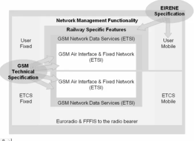
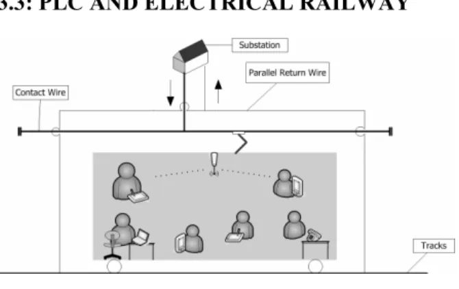
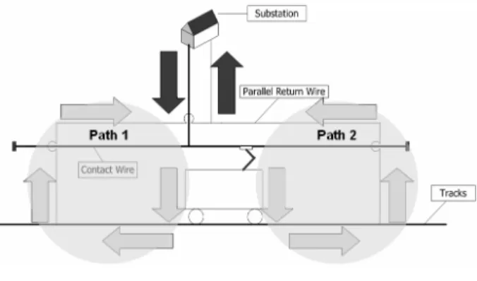
(2) The catenary wire is used to support the contact wire, which is hung by the dropper. The contact wire transmits the electricity to locomotives by the pantographs on the train. The pantograph is designed to retrieve the electricity from the contact wire by rubbing against it with the strips of graphite. The power circuit is completed by current’s flowing to tracks through the wheels, passing through the parallel return wire and then returning to the substation, as shown in Figure 3.. Figure 3 Electricity transmission circuit. 3: POWER LINE COMMUNICATIONS PLC is a technology that uses power distribution wires to transmit data simultaneously. PLC carrier is able to transfer data by overlaying an analog signal over the alternating current (AC) distributed by the power wires. The frequency of the alternation is usually 50 or 60 Hz. PLC includes Broadband over Power Lines (BPL) with data rates over 1 Mbps, which is almost as fast as the ordinary speed offered by the Internet service providers. The PLC is therefore gained much more attention in the past decade than before. Furthermore, high-speed data transmission has been developed using the lower voltage transmission lines used for power distribution. Home appliances are therefore is able to use a short-range form of power-line carrier to enable the home automation. There is Narrowband over Power Lines with much lower data rates, which has been actually utilized for more than thirty years. These traditional applications enable the electrical utilities to use low-speed power-line carrier circuits mainly for control purposes.. 3.1: BROADBAND OVER POWER LINES BPL uses the PLC technology to provide broadband Internet access through ordinary power lines. An internet-enabled device connects a BPL "modem", which is inserted into an outlet in an equipped building, to have high-speed Internet access. ETSI PLT [2] defines the standard specification of how the BPL uses the electric circuit between the electric substations and home networks to conduct high-speed data transmission or Broadband over Power Line. The data rate handled by a BPL modem is generally from 256 Kbps to 2.7 Mbps. The speed is able to promote to 45Mbps with the repeater situated in the meter room. To provide such data rate, BPL modems. transmit in the frequency of 1.6 to 30 MHz electric carrier. In the Medium Voltage (MV) grid, which is defined as less than 3 KV in Taiwan, stations the speed is able to be brought up to 135 Mbps. The connections to the Internet are established through the optical fiber backbone or wireless link.. 3.2: GIGABITS BPL Recently, much higher speed transmissions have been demonstrated using only a single power line conductor. According to Amirshahi and Kavehrad [3], the MV grid is a potentially excellent communications medium, offering bandwidths well beyond 100 MHz and potentially many gigahertzes, with Shannon capacities well into the gigabit range. Furthermore, because the workable frequency is anywhere in the 100 MHz - 10 GHz region, this Gigabits BPL technology is able to avoid the interference issues associated with utilizing spectrum shared with other services. Differences in the electrical distribution systems in the different electricity networks affect the implementation of BPL. In North America relatively few homes are connected to each distribution transformer, whereas in Europe there are hundreds of homes connected to each substation. Since the BPL signals do not propagate through the distribution transformers, extra equipment is needed in the North American case. In Taiwan, there are some researches and experiments conducted by the TaiPower Electrical Research Institute.. 3.3: PLC AND ELECTRICAL RAILWAY. Figure 4 Using PLC in a train As previous sections mentioned, the development of the broadband PLC grows up rapidly with the huge progress in the modulation and demodulation technologies during recent years. Using the PLC technology in the electrical railway systems allows the passengers operating their mobile gadgets with much more available bandwidth and more stability of the network links than the currently working cellular phone systems. In order to enable the Internet service for the train passengers, the possible solution of applying the PLC to the electrical railway system is to set a Wireless Access Point (WAP) in the train, as illustrated in Figure 4. The passengers therefore access Internet through the. - 688 -.
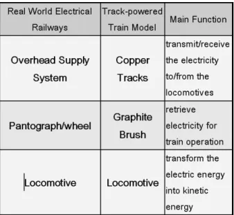
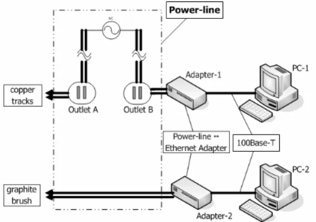
(3) power lines and so does the Voice over IP (VoIP) service for the vocal communication. To simulate the circumstances that the PLC is applied to the electrical railway system, a model similar to the real world railway system must be built, and the PLC devices which are responsible for transferring and coupling the network frames into the PLC signals are also needed. Since the MV power source used in the railway system is not available for this experiment, the indoor Low Voltage (LV) power source, AC 110V, is used in substitution. The Home-plug 1.0 [4] PLC devices are then chosen for this model system for its ability to be used with the indoor power source and to provide data rates up to 14Mbps. This experiment uses the Home-plug 1.0 compatible devices as the data transmitting units.. 4: DESIGN ISSUES. 4.1: MOBILE CONTACTS There are two mobile contacts, which are the pantograph and the wheels, in the power circuit of the real world electrical railway system. This experiment uses the graphite brushes with springs are used to simulate the pantograph. The springs on the graphite brushes provide resilience to keep the brushes touching the copper tracks and, on the other hand, forcing the wheels of the locomotive touching with the tracks for producing friction to drive the locomotive. The brushes with bases are fixed on the locomotive so that they can move firmly with it. Two copper tracks are placed in parallel above the locomotive to act as the OSS and become a part of the power lines. Figure 5 presents the deployment of the copper tracks and the graphite brushes on the locomotive.. In an electrical railway system, the main parts of the power supply system include: (1) Overhead Supply System (OSS): providing the electricity to the locomotive; (2) Pantograph: retrieving the electricity from the OSS for train operation; (3) Locomotive: transforming the electric energy into kinetic energy; (4) Tracks: retrieving and transmitting current from the wheels of the locomotive to the OSS. Table 1 summarizes the main parts described above. Table 1 Main function units in the electrical railway systems mapping to the train model. To simulate the situations of the PLC being applied to an electrical railway system, a track-powered train model with mobile contacts for the PLC is built. In this model a mini track-powered train model running on a circle track is used to simulate the real world electrical train system.. Figure 5 Deployment of the copper tracks and the graphite brushes on the locomotive. 4.2: POWER SUPPLY AND PLC SYSTEMS To reduce the unexpected problems which may occur in the experiment, the power source of the track-powered train model remains an independent DC power source as used in the original model. The power lines including the copper tracks are responsible for transmitting the PLC signals while the tracks of the train model are responsible for supplying DC power to the modified locomotive. This experiment focuses on the effectiveness of the digital data transmitted by the mobile contacts. The possible noise generated by the motor in the locomotive is not considered in this experiment. The PLC signals are transmitted and received through the power lines attached to two HomePlug 1.0 compatible PLC Ethernet adaptors. Orthogonal Frequency Division Multiplexing (OFDM) is the basic transmission technique used by the HomePlug. OFDM [5] is currently used in DSL technology [6], terrestrial wireless distribution of television signals, and has also been adapted for IEEE’s high rate wireless LAN Standards (802.11a and 802.11g). The basic idea of OFDM is to divide the available spectrum into several narrowband, low data rate subcarriers. To obtain high spectral efficiency the frequency response of the subcarriers are overlapping and orthogonal. Each narrowband subcarrier is modulated using different. - 689 -.
(4) modulation formats. By choosing the subcarrier spacing to be small, the channel transfer function reduces to a simple constant within the bandwidth of each subcarrier. In this way, a frequency selective channel is divided into many flat fading subchannels, which eliminates the need for sophisticated equalizers. The OFDM used by HomePlug uses 84 equally spaced subcarriers in the frequency band between 4.5MHz and 21MHz [7]. The cyclic prefix and differential modulation techniques (DBPSK, DQPSK) are used to completely eliminate the need for any equalization. [7] Impulsive noise events are overcome by means of forward error correction and data interleaving. HomePlug payload uses a concatenation of Viterbi and Reed-Solomon FEC. Sensitive frame control data is encoded using turbo product codes. The PLC Ethernet adaptors work with AC 110V power source and are capable of bridging the signals between Ethernet and PLC and coupling the PLC signals into power lines. The data path and circuit layout of the train model with the PLC devices is illustrated in Figure 6.. 4.3: TRACKS Figure 8 shows the materials, the train model components, and copper tracks used in this experiment.. Figure 8 Components used in this experiment The copper tracks illustrated in Figure 8 consist of two short straight tracks and two semicircular tracks, which are connected by the wires. The finished construction of the simulated electrical railway system is shown in Figure 9.. Figure 9 Simulated Electrical Railway System. Figure 6 Data Path and Circuit Layout As shown in Figure 6, to avoid the interference from the noise introduced by the other appliances connecting to the indoor power line network, a power transformer is used to provide a power source with no external noise for the experiment. Figure 7 shows the overall architecture of components used and their connections in this experiment.. Figure 7 Experiment Architecture. 4.4: MULTIPATH EFFECT For a broadband system, the power line generates considerably time-dispersion (ISI). This time dispersion is mainly due to the reflection at the end of a network branch with mismatched impedance. Delay spreads on the power line may differ between 10 and 300 ns, [8] and thus introduces the multipath effect [9]. According to HomePlug specification [7], the HomePlug uses the OFDM as its basic data transition technique. OFDM is an efficient way to deal with the multipath effect. OFDM uses several subcarriers instead of using a single carrier with an equalizer. For a given delay spread, the implementation complexity of handling the multipath effect is much lower in comparing to those of using a single carrier with an equalizer. When all parts are connected, the power line circuits, the copper tracks and the railroad, in the model form a ring structure. While an electrical-powered locomotive travels, the electrical current passes toward various directions and lead to a multi-path effect. It is shown in Figure 10.. - 690 -.
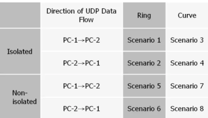
(5) stationary wire into a rotating device. However, should the slip ring be used to deal with this problem, there might be unexpected noise generated by it. To solve this, a rotating connector is needed to connect the power line and the locomotive. Figure 11 shows the connection of the slip ring, rotating connector and the model locomotive in the railway model platform.. 5: SETTINGS OF THE EXPERIMENT. Figure 10 Multipath Effect The multipath effect is simulated using the ring structure in this model. The simulation is shown in Figure 11.. Figure 13 A Configuration of the Interacting Devices Figure 11 Simulated Multi-path Effect. 4.5: ROTATABLE CONNECTION The experiment uses a personal computer (PC 1) to generate some network packets and send them to another personal computer. The model locomotive is too small to carry any device that is light enough. This experiment therefore uses an external connection cable to transmit the received signal to the designated receiving end, which is another personal computer (PC 2).. In the experiment, PC-1 is acted as the network service provider and PC-2 is acted as a mobile device used by a passenger in a train. To know the effectiveness of the PLC signals passing through the mobile contacts, this experiment uses a stream of UDP packet as the data source. UDP is an unreliable and unordered datagram protocol. It will drop the packet without retransmission when error occurs. Therefore, a stable UDP packet stream is suitable to observe the quality of data transmission because of the packet lost is able to be measured. The data size in a UDP packet is assigned to be a constant 1472 bytes so that every Ethernet frame maintains maximum size and needs no fragmentation. Figure 13 shows a configuration of the interacting devices.. 5.1: SCENARIOS OF THE EXPERIMENT. Figure 12 Slip Ring and Rotating Connector However, while the locomotive is moving along the tracks, the movement causes the connected line twisted and eventually broken. To resolve this problem, this experiment uses a slip ring that is able to carry the electrical current with the coupled signals from a. The scenarios of the data transmitted through mobile contacts between PC-1 and PC-2 are listed in Table 2. The “Direction of UDP Data Flow” column indicates which computer is acted as the data source. The “Ring” column indicates that the multi-path effect is simulated. The “Curve” column indicates that the multi-path effect is not simulated. The “Isolated” rows are the results of a power transformer being used to isolate the noise from the indoor power line network. The “Non-isolated” rows are the results of a power transformer being disconnected from the indoor power line network.. - 691 -.
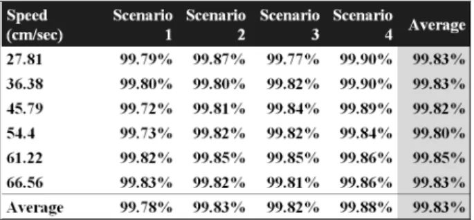
(6) Scenario 8 is to observe the situation of UDP packets transmitting from PC-2 to PC-1 in the power line network with the copper tracks not being fully connected, and no power transformer is used. In scenario 5, 6, 7 and 8, no power transformer is used in the experiment environment, where there are at least 4 sets of computers and monitors and other devices such as printers, wireless access points, etc.. Table 2 Scenarios of the Experiment. 5.2: SPEED OF THE LOCOMOTIVE. Figure 14 Ring Structure formed by the Clams Scenario 6 is to observe the situation of UDP packets transmitting from PC-2 to PC-1 in the power line network with the copper tracks connected to form a ring structure, and no power transformer is used. Scenario 7 is to observe the situation of UDP packets transmitting from PC-1 to PC-2 in the power line network with the copper tracks not being fully connected, and no power transformer is used.. Speed vs Input Voltage. Speed (cm/sec). Therefore, Scenario 1 is to observe the situation of UDP packets transmitting from PC-1 to PC-2 in the power line network with the copper tracks connected to form a ring structure, and a power transformer is used to isolate the noise from the indoor power line network. Scenario 2 is to observe the situation of UDP packets transmitting from PC-2 to PC-1 in the power line network with the copper tracks connected to form a ring structure, and a power transformer is used to isolate the noise from the indoor power line network. Scenario 3 is to observe the situation of UDP packets transmitting from PC-1 to PC-2 in the power line network with the copper tracks not being fully connected, similar to Figure 14 but with the unattached clams, and a power transformer is used to isolate the noise from the indoor power line network. Scenario 4 is to observe the situation of UDP packets transmitting from PC-2 to PC-1 in the power line network with the copper tracks not being fully connected, and a power transformer is used to isolate the noise from the indoor power line network. Scenario 5 is to observe the situation of UDP packets transmitting from PC-1 to PC-2 in the power line network with the copper tracks connected to form a ring structure, and no power transformer is used.. In these eight scenarios the mobile contacts (the graphite brushes) are moving at various speeds to evaluate the success rate of UDP data transmission with or without the external noise induced, as well as the involvement of the multi-path effect. The speed of the graphite brushes is as same as the speed of the locomotive. The speed of the locomotive is determined by the input voltage, that is ranging from DC 10V to DC 15V, to the track. The speeds of the locomotive according to the input voltages are shown in Figure 15.. 70 65 60 55 50 45 40 35 30 25. 10V. 11V. 12V. 13V. 14V. 15V. Speed vs Input Voltage 27.81. 36.38. 45.79. 54.4. 61.22. 66.56. Input Voltage. Figure 15 Speed of the Locomotive according to the Input Voltage. 5.3: EXPERIMENT PROGRAMS. PLATFORMS. AND. PC-1 and PC-2 are both equipped with the same specification, which consists of an Intel Celeron 2.66 GHz CPU and 256 MB DDR RAM. The operating systems are both Microsoft Windows XP Professional Service Pack 2. The packet sending and receiving programs are written in C++ using the Winsock2 library for the socket programming, compiled by Microsoft Visual C++ 6.0 compiler. The number of UDP packets transmitted for each test is 50000, about 72MB in total size. Evaluations of the effectiveness are obtained by calculating the successfully received UDP packets against the sent packets.. 6: EXPERIMENT RESULTS The scenarios of the mobile contacts between PC-1 and PC-2 are listed in Table 2. Scenario 1 represents the situation of UDP packets transmitting from PC-1 to PC-2. - 692 -.
(7) r SuccessRate = ( ) s r is the number of successfully received UDP packets. s is the number of sent UDP packets, which is 50000 in the experiment.. 1 0.99 0.98 0.97 0.96 0.95 27.81 36.38 45.79. 54.4. 61.22 66.56. Speed (cm/sec). Figure 16 Success Rate of Scenario 1 Scenario 2. Success Rate. Table 3 Average Success Rate of Scenario 1 - 4. Scenario 1. Success Rate. in the power line network with the copper tracks connected with the calms to form a ring, in which the power transformer is used to isolate the noise from the indoor power line network. The situation of UDP packets transmitting from PC-2 to PC-1 in the power line network with the copper tracks formed as a open to a curve, in which the power transformer is used to isolate the noise from the indoor power line network, is evaluated in Scenario 4. Scenario 2 is basically the same as scenario 1 other than the UDP data flow is sent from PC-2, so is scenario 3 in comparing with scenario 4. Scenario 5, 6, 7, and 8 are basically the same as the scenario 1, 2, 3 and 4 except the power transformer is removed from the experiment. In these eight scenarios the mobile contacts (the graphite brushes) are moving at various speeds to evaluate the data transmission with or without the external noise induced, and with or without the multi-path effect. In scenario 1, 2, 3 and 4, the power transformer is used to evaluate the effectiveness of the data transmission without the external noise. The power transformer is removed to evaluate the effectiveness of the data transmission when the unexpected noise might interfere in scenario 5, 6, 7 and 8. Table 3 shows the average success rate of scenario 1, 2, 3 and 4.. 1 0.99 0.98 0.97 0.96 0.95 27.81 36.38 45.79. 54.4. 61.22 66.56. Speed (cm/sec). Figure 17 Success Rate of Scenario 2 Table 4 shows the average success rate of scenario 5, 6, 7 and 8.. Scenario 3. Success Rate. Table 4 Average Success Rate of Scenario 5 - 8. 1 0.99 0.98 0.97 0.96 0.95 27.81 36.38 45.79. 54.4. 61.22 66.56. Speed (cm/sec). Figure 18 Success Rate of Scenario 3 From Table3 and Table 4, the success rates of UDP packets all exceed 99.6% that indicates the mobile contacts at the given speeds are able to transmit data properly. The following eight figures (Figure 16 ~ Figure 23) show the success rate of each scenario. The success rate is calculated as:. - 693 -.
(8) Scenario 8. 1 0.99 0.98 0.97 0.96 0.95. Success Rate. Success Rate. Scenario4. 27.81 36.38 45.79. 54.4. 1 0.99 0.98 0.97 0.96 0.95. 61.22 66.56. 27.81 36.38 45.79. Speed (cm/sec). 54.4. 61.22 66.56. Speed (cm/sec). Figure 19 Success Rate of Scenario 4. Figure 23 Success Rate of Scenario 8. Scenario 5. Average Success Rate of each Scenario. 0.99 Success Rate. Success rate. 1. 1 0.99 0.98 0.97 0.96 0.95. 0.98 0.97 0.96 0.95. 27.81 36.38 45.79. 54.4. 61.22 66.56. Scenario Scenario Scenario Scenario Scenario Scenario Scenario Scenario 1 2 3 4 5 6 7 8. Scenarios 0.99782 0.99828 0.99818 0.99875 0.99763 0.99842 0.99763 0.99833 Scenarios. Speed (cms/sec). Figure 24 Average Success Rates of all Scenarios. Figure 20 Success Rate of Scenario 5. Average Success Rate of each Speed 1 0.99. 1 0.99 0.98 0.97 0.96 0.95. Success Rate. Success Rate. Scenario 6. 0.97 0.96 0.95. 27.81 36.38 45.79. 54.4. Scenario 7 1 0.99 0.98 0.97 0.96 0.95 54.4. 36.4. 45.8. 54.4. 0.998125. 0.9979. 0.99795. 61.2. 66.6. 0.9983125 0.9982125. Speed (cm/sec). Figure 25 Average Success Rates at Different Speeds. Figure 21 Success Rate of Scenario 6. 27.81 36.38 45.79. 27.8. Speed 0.9982875. 61.22 66.56. Speed (cm/sec). Success Rate. 0.98. 61.22 66.56. Speed (cm/sec). Figure 22 Success Rate of Scenario 7. Figure 24 shows the average success rates of all scenarios. Figure 25 shows the average success rate at the different speeds. The experiment results show that all of these scenarios have very low packet lost rate while transmitting 50000 UDP packets. The locomotive traveling at the different speeds does not affect the success rates of receiving UDP packets, which are all more than 99.6%. However, the result shows only that the performance remains acceptable when the moving speed less than 70 cm/s, or 2.5 km/hr. The effect of jitters, which are introduced by rubbing the graphite brushes against the copper tracks, is not observable in this experiment, neither the multipath effect. Different from the other PLC applications, this experiment uses a moving transceiver. When the receiver is moving, there is frequency offset introduced. - 694 -.
(9) by Doppler Effect [9]. The frequency offset fm is obtained by:. f m = VR ×. fc C. The fc, the frequency band used by HomePlug 1.0, is between 4.5MHz and 21MHz [7]. Therefore, the frequency offset, using the speed of 70 cm/sec = 0.7 m/sec, is between:. f m = VR ×. fc 4.5 ×10 6 = 0.0105 Hz = 0.7 × C 3 × 10⁸. and. fc 21× 10 6 f m = VR × = 0.7 × = 0.049 Hz C 3 × 10 8 Obviously, the moving speed of the locomotive in this experiment is less than 70 cm/s, under which Doppler Effect is therefore ignored. According to Amirshahi and Kavehrad [3], the average capacity in this network with a 10 dBm launched transmit power level at 50 MHz band is about 300 Mbps. Considering the average moving speed, which is about 300Km/hr = 250/3 m/sec, of Taiwan High Speed Rail System (THSR), the frequency offset of the operating frequency of 50 MHz is:. f m = VR ×. f c 250 50 × 10 = × = 14.89 Hz C 3 3 × 10⁸. standard, repeatable process. Furthermore, the amount of bandwidth provided by a BPL system comparing to cable and wireless is still in question. However, on August 8, 2006 United States FCC sees the great potential of BPL and permits the BPL stockholders to promote BPL service to all Americans.[10][11] FCC chief Kevin Martin said that "holds great promise as a ubiquitous broadband solution that would offer a viable alternative to cable, digital subscriber line, fiber, and wireless broadband solutions," and that BPL was one of the agency's "top priorities." The obvious advantage of using PLC in the electrical railway systems is the well established power line infrastructure. Furthermore, the PLC modules providing bandwidth up to 200 Mbps or even higher have been developed. It is attractive being able to access the Internet with large bandwidth in a running train in the future than just to have vocal communications. However, to be able to achieve the goal of using PLC in the electrical railway systems still has a long way to go. The following sections issues some problems that require further study in the future for applying PLC in the electrical railway systems.. 7.2: NEUTRAL ZONE. 6. This effect combined with other effects introduced by the high speed movement to the data transmission using the mobile PLC is still unknown, which requires further examinations in the future experiments.. 7: CONCLUSIONS This experiment is one of the very first attempts to examine the possibility of using PLC as the communication system of the electrical railway systems. This paper shows that using the PLC technology to transmit the network packets instead of using the wireless communication system, such as the cellular phones, is a possibility in an electrical railway system. A low speed electrical railway system model that transmits the network data using PLC with mobile contacts is built and tested. The experiment results show that there is no significant data lost with the mobile contacts moving in the power circuit at the speeds under 70 cm/sec.. 7.1: THE BRIGHT FUTURE OF BPL BPL offers obvious benefits over the regular cable or DSL connections for the extensive infrastructure, the power distribution grid, already available to allow more people in more locations to have access to the Internet. Such ubiquitous availability makes it much easier for other electrical home appliances, such as televisions or sound systems, to hook up. On the other hand, variations in the physical characteristics of the electricity network and the current lack of standards mean that provisioning of the service is far from being a. The data transmission in the case that the train passing through the Neutral Zone, which is responsible for isolating two independent power sources and the OSS here is usually concatenated by insulators, remains a problem for the power supply will be interrupted. The interruption of the power supply in the Neutral Zone introduces another issue: how to keep the services, i.e. the network connections, available while the train passing through the Neutral Zone.. 7.3: ELECTROMAGNETIC INTERFERENCE Although PLC is intended to be wire bound, a certain impact on wireless services seems inevitable because power distribution networks are electromagnetically open. In reality, the wavelengths of the utilized carrier frequencies, which are at the megahertz level, are comparable to the dimensions of the power-line system. The PLC radiation from such broadband signal transmission and the potential of impact to other communications systems must be addressed. [12] In particular, the power networks in the electrical railway system are usually unshielded. The effects of the electromagnetic interference (EMI) that affects the surrounding areas and EMI that affects the signals transmitted through power lines from the surroundings still require being examined more.. 7.4: THE FADING OF SIGNALS Though PLC is able to be applied to LV and MV power networks with good performance, PLC signal, due to its high frequency, fades very fast within a very. - 695 -.
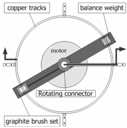
(10) short distance. In a building, this problem is easily solved by using a repeater. Considering the environment that the PLC is applied to the railway power system, a better solution than using repeaters is needed to meet the balance between cost and performance.. 8: FUTURE WORKS. gathering information of the mobile contacts moving at a higher speed as a following task. Figure 26 shows a possible platform to examine the effects of the mobile contacts with higher speed. The speed of the mobile contact comes to 377 km/h easily, with the plate of 1 meter in radius and the motor rotating at 1000 rpm. The vertical view of the possible platform is illustrated in Figure 27.. Figure 26 Experiment Model for a Higher Speed (Front Elevation). Figure 27 Experiment Model for a Higher Speed (Vertical View). Due to the speed limitation of the model locomotive, the effects of the mobile contacts at a higher speed remain as an unknown subject. To better understand and evaluate the effects introduced by a higher speed, this paper proposes new experiment architecture for. REFERENCES [1] M. Watkins, “Project EIRENE. A new radio system for the European railways,” International Conference on Public Transport Electronic Systems 1996, pp. 52-56, May 1996 [2] ETSI PLT, Powerline Telecommunications (PLT) Technical requirements for In-House PLC modems, ETSI Power Telecommunication, 2005 [3] P. Amirshahi and M. Kavehrad, “Transmission channel model and capacity of overhead multi-conductor medium-voltage power-lines for broadband communications,” in Proc. CCNC, Las Vegas, NV, pp. 354–358 , Jan. 2005 [4] K.H. Afkhamie, S. Katar, L. Yonge, and R. Newman, “An overview of the upcoming HomePlug AV standard,” 2005 International Symposium on Power Line Communications and Its Applications, pp. 400 – 404, April 2005 [5] J.A.C. Bingham, “Multicarrier Modulation for Data Transmission: An Idea Whose Time Has Come,” IEEE Communications Magazine, pp. 5-14, May, 1990. [6] J.G. Proakis, Digital Communications, McGraw Hill, 1995. [7] HomePlug 1.0 Technology White Paper, http://www.homeplug.com. [8] W. Liu, H.-P. Widmer, J. Aldis, and T. Kaltenschnee, “Nature of power line medium and design aspects for broadband PLC system,” 2000 Proceedings International Zurich Seminar on Broadband Communications., pp. 185. -189, 2000 [9] Y.H. Ma, P.L. So, E. Gunawan, and Y.L. Guan, “Analysis of impulsive noise and multipath effects on broadband power line communications,” PowerCon 2004. 2004 International Conference on Power System Technology, Vol. 2, pp. 1404 – 1409, Nov. 2004. [10] The Federal Communications Commission, http://www.fcc.gov/ [11] G Goth, “Third wire or third rail? [Broadband Internet access],” IEEE Internet Computing, Vol. 8, Issue 4, pp. 7 – 9, July-Aug. 2004 [12] W. Luo, S.Y. Tan, “A radiated emission model for power-line communications,” IEEE Transactions on Power Delivery, Vol. 21, Issue 3, pp. 1245 – 1249, July 2006. - 696 -.
(11)
數據
+5
相關文件
Reading Task 6: Genre Structure and Language Features. • Now let’s look at how language features (e.g. sentence patterns) are connected to the structure
Promote project learning, mathematical modeling, and problem-based learning to strengthen the ability to integrate and apply knowledge and skills, and make. calculated
Now, nearly all of the current flows through wire S since it has a much lower resistance than the light bulb. The light bulb does not glow because the current flowing through it
好了既然 Z[x] 中的 ideal 不一定是 principle ideal 那麼我們就不能學 Proposition 7.2.11 的方法得到 Z[x] 中的 irreducible element 就是 prime element 了..
Using this formalism we derive an exact differential equation for the partition function of two-dimensional gravity as a function of the string coupling constant that governs the
Define instead the imaginary.. potential, magnetic field, lattice…) Dirac-BdG Hamiltonian:. with small, and matrix
This kind of algorithm has also been a powerful tool for solving many other optimization problems, including symmetric cone complementarity problems [15, 16, 20–22], symmetric
Therefore, every Buddha’s Light member who vows to practice the bodhisattva path needs to cultivate bodhi wisdom and the power of vows in order to change the world and benefit
