IEEE MICROWAVE AND WIRELESS COMPONENTS LETTERS, VOL. 12, NO. 10, OCTOBER 2002 383
Parallel Coupled Microstrip Filters With
Suppression of Harmonic Response
Jen-Tsai Kuo, Member, IEEE, Wei-Hsiu Hsu, and Wei-Ting Huang
Abstract—Corrugated coupled microstrip lines are proposed to design planar microwave filters with suppression of spurious re-sponse at twice the center frequency(2 ). The corrugated struc-ture is designed to equalize the phase velocities of the two eigen-modes in the propagation direction. The designed bandpass filters have a wide upper stopband with satisfactory attenuation levels. In addition, the symmetry of the passband response is improved. Mea-sured results of two fabricated circuits show that the idea works very well.
Index Terms—Corrugated microstrip, microstrip filter, spurious response.
I. INTRODUCTION
F
ILTERS are essential in the RF front end of microwave wireless communication systems. In planar microstrip re-alization, one of the most common implementation methods is to use a cascade of parallel coupled sections, since the synthesis procedure [1] is easy and a wide range of filter fractional band-width is achievable [2].The tradition design of parallel coupled microstrip filter suf-fers from the spurious response at twice the basic passband fre-quency [2], [3], which causes response asymmetry in the upper and lower stopbands, and could greatly limit its applica-tions; it is resulted from the inequality of the even and odd mode phase velocities of the coupled lines in each stage. This problem becomes more severe if inverted microstrip and suspended- sub-strate stripline are used, since these two media exhibit a consid-erably greater difference in mode velocities [3].
Many works [3]–[6] have been proposed to tackle this problem. They fall into two categories [4]: providing different lengths for the even and odd modes and equalizing the modal phase velocities. It is found in [3] that connecting a short uncoupled line section at either end of the coupled section can improve the filter characteristics, if the section lengths are chosen correctly. In [4], an overcoupled resonator is proposed to extend phase length for the odd mode to compensate difference in the phase velocities. Subsections with a coupled three-line microstrip are inevitable at both ends of each coupled section in the filter. The capacitively compensated structures [5], [6]
Manuscript received February 20, 2002; revised April 22, 2002. This work was supported in part by the National Science Council, Taiwan, R.O.C, under Grant NSC 90-2213-E-009-062, and in part by the joint program of the Ministry of Education and the National Science Council under the Contract 89-E-F-A06-2-4. The review of this letter was arranged by Associate Editor Dr. Ruediger Vahldieck.
The authors are with the Department of Communication Engineering, National Chiao Tung University, Hsinchu, Taiwan, R.O.C. (e-mail: [email protected]).
Digital Object Identifier 10.1109/LMWC.2002.804559.
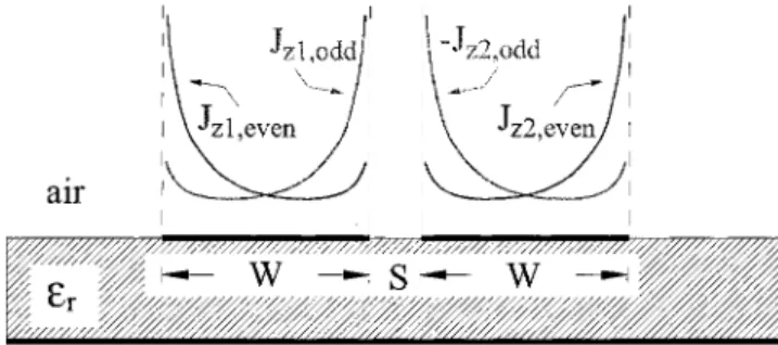
Fig. 1. Typical current distributions of the odd- and even-modes of a pair of symmetric coupled microstrips.
are also effective in suppressing the spurious passband at . It should be noted that the values of the loading capacitors are subject to the electrical parameters of each coupled section.
Recently, [7] combines different stripline-stepped impedance resonators (SIR) with specified coupling angles to suppress the spurious responses. In [8], the gap size and the linewidth for the input/output coupled resonators are reduced to improve the re-jection of the filter at . The coupled wiggly microstrip lines in [9] also show an effective suppression on the spurious pass-band. The strip-width perturbation does not require the filter parameters to be recalculated, and the classical design method-ology for coupled-line microstrip filters can still be used.
Here, we introduce corrugated coupled microstrip lines as building blocks for constructing parallel coupled-line filters. Section II explains the technical background of the idea, and Section III compares the predicted and measured responses with the traditional design method using two fabricated band-pass filters. Section IV draws the conclusion.
II. THEIMPROVEDDESIGN
Along a pair of symmetric coupled microstrip lines, the odd mode propagates faster than the even mode, i.e., . Thus, if a coupled section with identical even and odd mode electrical lengths is required, the traveling path for the odd mode should be extended. It is known that, of symmetric coupled microstrips, typical current distributions of the odd and even modes are those shown in Fig. 1. It clearly indicates that electromagnetic energy for the odd mode gathers around the center gap, while for the even mode, it gathers around the outer metallic edges. Thus, a possible way to extend the path for the odd mode, and to increase that for the even mode to a minimal extent at the same time, is to alter the flat coupled lines to corrugated coupled lines, as shown in Fig. 2. The coupled lines, of course, are no longer symmetric with respect to the propagation direction. The even and odd modes of symmetric coupled lines are perturbed and
384 IEEE MICROWAVE AND WIRELESS COMPONENTS LETTERS, VOL. 12, NO. 10, OCTOBER 2002
(a)
(b)
Fig. 2. Layouts for the fabricated microstrip filters. The dimensions are in mm. (a) Maximally flat filter of orderN = 1. (b) Chebyshev filter of order N = 3; only half of the circuit is plotted.
turn into -mode and -mode, respectively. Most of the energy of the -mode will travel along the central wiggle coupling slot, while that of the -mode along the straight outer metallic edges. Thus, the total electrical lengths of these two eigen-modes in a coupled section can be equalized, i.e., , since the path
length and phase constant .
The design procedure for the circuit is as follows. First, the classical synthesis method, e.g., [1], is used to determine the linewidth and gap spacing for each coupled section. Then, for each section, the slot trace is indented. For an initial design, the width of the gap is kept the same all the way along the slot in a coupled section. A possible pattern for the indentation is to use a periodic rectangular-wave contour, as shown in Fig. 2. The pur-pose for choosing rectangular-wave shape is for the ease of sim-ulation, as well as fabrication. The more indentation periods in a section, the more possible radiation loss is expected. The fewer periods in a section, on the other hand, the less effectiveness in phase velocity equalization can be achieved. In our case studies, five periods in a section are found to best meet these two require-ments. Finally, the section length is adjusted to finely trim the center frequency. For a multistage filter, the above procedure is applied to every section before the whole circuit is constructed for simulation.
III. MEASUREDRESULTS
We use the full-wave simulator IE3D [10] to do the CAD work before the circuits are fabricated. Fig. 2(a) shows the de-tailed layout of the first fabricated bandpass filters with maxi-mally flat response of order , and Fig. 2(b) shows that of the second filter with Chebyshev response of and ripple level 0.01 dB, respectively. All dimensions are in millimeters. The filters are made on substrate with 10.2 (RT/duroid 6010) and thickness 1.27 mm. Their fractional bandwidth 10%, and the center frequency 2.45 GHz. The filter of has four coupled sections; only the first two cou-pled sections are shown for saving the plot area. It is found that the length for a coupled section with indented slot is about 10% shorter than that with straight slot.
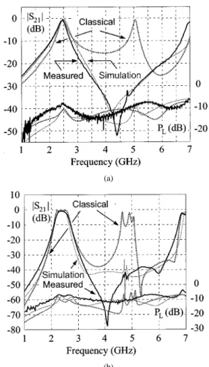
There are three (in dB) curves in Fig. 3(a) and (b). The response labeled “classical” is the simulation for filter designed with ordinary coupled lines, of which the spurious passband at seriously deteriorates the filter rejection at upper stopband.
(a)
(b)
Fig. 3. Simulation and measured responses for the fabricated filters. Structural parameters are in Fig. 2. (a) Maximally flat filter of orderN = 1. (b) Chebyshev filter of orderN = 3.
The responses labeled with “measured” and “simulation” are for filters with indented slots, and they are in good agreement. At least 30 dB of spurious response suppression around is achieved. The dip of the measured response in the upper stop-band for the maximally flat filter with is below 50 dB, and that for the Chebyshev filter with is better than 70 dB. Since the attenuation of the fabricated filter in upper stop-band is greatly enhanced, the passstop-band response symmetry with respect to the center frequency is also greatly improved.
Also plotted in Fig. 3(a) and (b) is the total power loss of the circuit, which is calculated as (dB)
. The simulation responses for the classical and indented slot designs have comparative magnitudes. The measured re-sults for the fabricated circuits are 1–2 dB higher than the sim-ulation in the fundamental passband.
IV. CONCLUSION
Corrugated coupled microstrip lines are proposed to form the building blocks for planar microstrip filters with suppression of the spurious passband at the second harmonic. The response symmetry of the filter is also greatly improved. For the particular case studies shown here, a corrugated coupled section is about 10% shorter than that of a flat line section, and the measured
KUO et al.: PARALLEL COUPLED MICROSTRIP FILTERS WITH SUPPRESSION OF HARMONIC RESPONSE 385
results show that a harmonic rejection of at least 30 dB can be achieved.
REFERENCES
[1] D. M. Pozar, Microwave Engineering, 2nd ed. New York: Wiley, 1998. [2] C.-Y. Chang and T. Itoh, “A modified parallel-coupled filter structure that improves the upper stopband rejection and response symmetry,”
IEEE Trans. Microwave Theory Tech., vol. 39, pp. 310–314, Feb. 1991.
[3] B. Easter and K. A. Merza, “Parallel-coupled-line filters for inverted-mi-crostrip and suspended-substrate MICs,” in 11th Eur. Microwave Conf.
Dig., 1981, pp. 164–167.
[4] A. Riddle, “High performance parallel coupled microstrip filters,” in
IEEE MTT-S Symp. Dig., 1988, pp. 427–430.
[5] S. L. March, “Phase velocity compensation in parallel-coupled mi-crostrip,” in IEEE MTT-S Symp. Dig., 1982, pp. 410–412.
[6] I. J. Bahl, “Capacitively compensated high performance parallel coupled microstrip filters,” in IEEE MTT-S Symp. Dig., 1989, pp. 679–682. [7] M. Makimoto and S. Yamashita, Microwave Resonators and Filters
for Wireless Communication—Theory and Design. Berlin, Germany: Springer, 2001, pp. 79–83.
[8] C. Wang and K. Chang, “Microstrip multiplexer with four channels for broadband system applications,” Int. J. RF Microwave CAE 11, pp. 48–54, Nov. 2001.
[9] T. Lopetegi, M. A. G. Laso, J. Hernández, M. Bacaicoa, D. Benito, M. J. Garde, M. Sorolla, and M. Guglielmi, “New microstrip ‘wiggly-Line’ filters with spurious passband suppression,” IEEE Trans. Microwave
Theory Tech., vol. 49, pp. 1593–1598, Sept. 2001.