國 立 交 通 大 學
電信工程研究所
碩 士 論 文
於上行傳輸多點協調系統中利用高效率
干擾校齊之收發器設計
Efficient Interference Alignment Aided Transceiver
Design in Uplink Coordinated Multipoint Systems
研 究 生:鍾綱撼
Student: Gang-Han Chung
指導教授:李大嵩 博士
Advisor: Dr. Ta-Sung Lee
指導教授:鍾偉和 博士
Advisor: Dr. Wei-Ho Chung
於上行傳輸多點協調系統中利用高效率
干擾校齊之收發器設計
Efficient
Interference Alignment Aided Transceiver
Design in Uplink Coordinated Multipoint Systems
研 究 生:鍾綱撼
Student: Gang-Han Chung
指導教授:李大嵩博士
Advisor: Dr. Ta-Sung Lee
指導教授:鍾偉和博士
Advisor: Dr. Wei-Ho Chung
國立交通大學
電信工程研究所
碩士論文
A Thesis
Submitted to Institute of Communications Engineering
College of Electrical and Computer Engineering
National Chiao Tung University
in Partial Fulfillment of the Requirements
for the Degree of
Master of Science
in
Communications Engineering
July 2013
Hsinchu, Taiwan, Republic of China
於上行傳輸多點協調系統中利用高效率
干擾校齊之收發器設計
學生:鍾綱撼
指導教授:李大嵩 博士
學生:鍾綱撼
指導教授:鍾偉和 博士
Chinese Abstract
國立交通大學電信工程研究所碩士班
摘要
由於鄰近細胞所造成的干擾會嚴重降低在現今無線細胞通訊系統中非常重 要的系統效能,因此干擾必須被謹慎地處理。為了解決這個問題,第三代合作夥 伴專案(third generation partnership project; 3GPP)在前瞻長程演進系統(Long Term Evolution-Advanced; LTE-A)中提出新穎的多點協調(coordinated multipoint; CoMP) 傳輸與接收技術。在本篇論文中,吾人嘗試於上行傳輸多點協調系統中引入干擾 校齊(interference alignment; IA)技術進而提升總傳輸速率。為了加快收斂速度,吾人進一步提出兩種高效率的干擾校齊演算法。其一為區塊QR 分解輔助干擾校齊
(block QR decomposition aided IA; BQRD aided IA),它引入序列式干擾消除 (successive interference cancellation; SIC) 的 概 念 。 另 一 為 兩 階 段 式 干 擾 校 齊 (two-stage IA),它則是最佳化等效通道的結構並且引入功率載荷(power loading)。 經由模擬驗證,吾人所提出的兩種演算法有較佳的收斂特性並且擁有和最大信號 雜訊干擾比(signal-to-interference-plus-noise ratio; SINR)干擾校齊相近的總傳輸速 率。由於僅需要較少迭代次數即可收斂,吾人提出的演算法更適合於實際應用。
Efficient Interference Alignment Aided Transceiver
Design in Uplink Coordinated Multipoint Systems
Student: Gang-Han Chung
Advisor: Dr. Ta-Sung Lee
Student: Gang-Han Chung
Advisor: Dr. Wei-Ho Chung
English Abstract
Institute of Communications Engineering
National Chiao Tung University
Abstract
The interference from other cells, which severely degrades the system performance, is a critical factor in modern wireless cellular communication systems and should be carefully managed. To tackle this problem, a new coordinated multipoint (CoMP) transmission and reception technique is proposed by the 3GPP in the LTE-A system. In this thesis, we attempt to incorporate interference alignment (IA) into uplink CoMP systems to improve the sum-rate performance. To boost convergence rate, we further propose two efficient IA aided transceiver designs for the uplink CoMP systems. One is the block QR decomposition (BQRD) aided IA that incorporates the concept of successive interference (SIC). The other is the two-stage IA that optimizes the structure of the effective channel and employs power loading. From simulation results, the proposed algorithms exhibit better convergence behavior and have comparable performance to the max-SINR IA. Requiring only a small number of iterations to converge, the proposed algorithms are suitable to practical applications.
Acknowledgement
I would like to thank for my advisor, Dr. Ta-Sung Lee, and my co-adivsor, Dr. Wei-Ho Chung, for their enthusiastic guidance, immense knowledge, and insightful comments. I learned a lot from their aggressive attitude in many aspects. I also wish to express appreciation to my senior, Chung-Jung Huang, for giving me countless precious guidance and suggestions on the research. I would also like to thank my friends and all members in the Communication System Design and Signal Processing (CSDSP) Lab for their encouragement and help. Last but not least, I would like to show my sincere thanks to my parents for supporting me spiritually throughout my life.
Table of Contents
Chinese Abstract ... i
English Abstract ... ii
Table of Contents ... iv
List of Figures ... vi
List of Table ... ix
Acronym Glossary ... x
Notations ... xi
Chapter 1 Introduction ... 1
Chapter 2 System Model ... 4
2.1 Coordinated Multipoint (CoMP) Transmission and Reception in LTE-A ... 5
2.2 Uplink CoMP System Model ... 9
2.3 Interference Alignment in K-User Systems ... 12
2.4 Summary ... 14
Chapter 3 Interference Alignment (IA) Aided Transceiver Design
in Uplink CoMP Systems ... 15
3.1 Motivation ... 16
3.2 Degrees of Freedom ... 16
3.3 Incorporation of Interference Alignment in Uplink CoMP Systems ... 20
3.3.1 Min-Leakage IA in Uplink CoMP Systems ... 23
3.4 Computer Simulations ... 26
3.5 Summary ... 28
Chapter 4 Proposed Efficient Interference Alignment in Uplink
CoMP Systems ... 29
4.1 Motivation ... 30
4.2 Proposed Block QR Decomposition Aided IA Algorithm ... 31
4.2.1 Proposed Algorithm ... 31
4.2.2 Computer Simulations ... 35
4.3 Proposed Two-Stage IA Algorithm ... 40
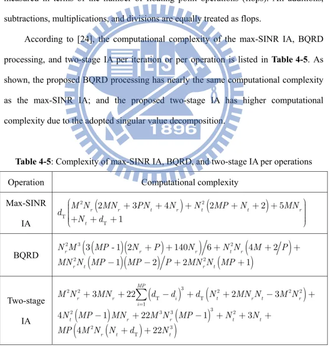
4.4 Complexity Analysis of Proposed Interference Alignment Algorithms ... 44
4.5 Computer Simulations ... 45
4.6 Summary ... 50
Chapter 5 Conclusions and Future Works ... 51
List of Figures
Figure 2–1: CoMP scenario 1 [5]. ... 5
Figure 2–2: CoMP scenario 2 [5]. ... 6
Figure 2–3: CoMP scenario 3/4 [5]. ... 6
Figure 2–4: Joint transmission in downlink CoMP transmission. ... 7
Figure 2–5: Dynamic cell selection in downlink CoMP transmission. ... 7
Figure 2–6: Coordinated scheduling/beamforming in downlink CoMP transmission. ... 8
Figure 2–7: Interference rejection combining in uplink CoMP reception. ... 8
Figure 2–8: Coordinated scheduling in uplink CoMP reception. ... 8
Figure 2–9: Illustration of centralized IA aided uplink CoMP system model. ... 12
Figure 2–10: Illustration of IA in K-user interference channel. ... 14
Figure 3–1: Illustration of point-to-point MIMO channel. ... 17
Figure 3–2: Illustration of MAC channel. ... 18
Figure 3–3: Illustration of K-user interference channel. ... 19
Figure 3–4: Illustration of equivalence between K-user channel with full cooperation at the receiver side and MAC-like channel. ... 19
Figure 3–5: Illustration of information exchange procedure of UL CoMP systems with IA techniques. ... 20
Figure 3–6: Illustration of information exchange procedure of DL CoMP systems with IA techniques. ... 21
Figure 3–8: Convergence behavior of max-SINR IA and min-leakage IA in UL
CoMP systems with PUPW =30 and 40 dB. ... 27
Figure 3–9: Sum-rate performance of CoMP without IA, max-SINR IA, and
min-leakage IA in uplink CoMP systems with 5 and 8000 iterations. ... 28
Figure 4–1: Convergence behavior of max-SINR IA and BQRD aided IA in
UL CoMP systems with PUPW =20 30, and 40dB. ... 37
Figure 4–2: Sum-rate performance of BQRD aided IA with 5 iterations and max-SINR IA with 5 and 8000 iterations in UL CoMP. ... 37
Figure 4–3: Convergence behavior of max-SINR IA and BQRD aided IA in UL CoMP systems with PUPW =20 30, and 40 dB in typical CoMP scenario. ... 38
Figure 4–4: Sum-rate performance of BQRD aided IA with 5 iterations and max-SINR IA with 5 and 8000 iterations in typical CoMP scenario. .... 38
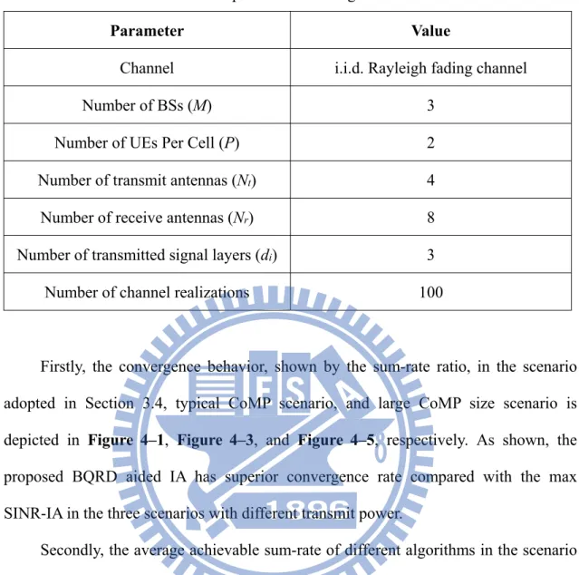
Figure 4–5: Convergence behavior of max-SINR IA and BQRD aided IA in UL CoMP systems with PUPW =20 30, and 40 dB in large CoMP size scenario. ... 39
Figure 4–6: Sum-rate performance of BQRD aided IA with 5 iterations and max-SINR IA with 5 and 8000 iterations in large CoMP size scenario. 39
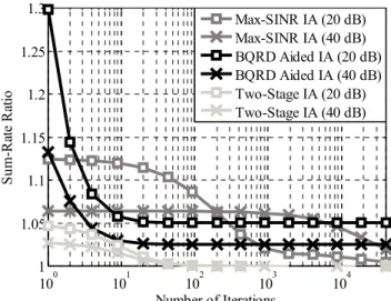
Figure 4–7: Convergence behavior of two-stage IA, BQRD aided IA, and max-SINR IA in UL CoMP systems with PUPW =20 and 40dB. ... 47
Figure 4–8: Sum-rate performance of two-stage IA, BQRD aided IA, and max-SINR IA in UL CoMP systems. ... 47
Figure 4–9: Convergence behavior of two-stage IA, BQRD aided IA, and max-SINR IA in UL CoMP systems with PUPW =20and 40dB in
typical CoMP scenario. ... 48
Figure 4–10: Sum-rate performance of two-stage IA, BQRD aided IA, and max-SINR IA in typical CoMP scenario. ... 48
Figure 4–11: Convergence behavior of two-stage IA, BQRD aided IA, and max-SINR IA in UL CoMP systems with PUPW =20and 40dB in large CoMP size scenario. ... 49
Figure 4–12: Sum-rate performance of two-stage IA, BQRD aided IA, and max-SINR IA in large CoMP size scenario. ... 49
List of Table
Table 3-1: An information exchange procedure of UL CoMP systems with IA
techniques ... 20
Table 3-2: An information exchange procedure of DL CoMP systems with IA techniques ... 21
Table 3-3: A procedure for min-leakage IA in UL CoMP systems ... 24
Table 3-4: A procedure for max-SINR IA in UL CoMP systems ... 25
Table 3-5: Simulation parameters ... 26
Table 4-1: A procedure for BQRD aided IA in UL CoMP systems ... 34
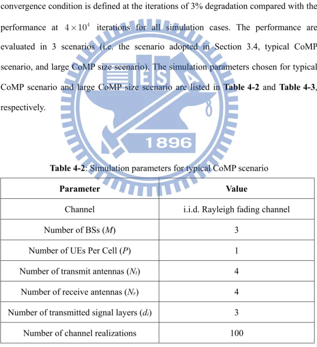
Table 4-2: Simulation parameters for typical CoMP scenario ... 35
Table 4-3: Simulation parameters for large CoMP size scenario ... 36
Table 4-4: A procedure for two-stage IA in UL CoMP systems ... 43
Table 4-5: Complexity of max-SINR IA, BQRD, and two-stage IA per operations ... 44
Table 4-6: Complexity reduction ratio of proposed algorithms in convergence ... 49
Acronym Glossary
3GPP third generation partnership project AWGN additive white Gaussian noise
BS base station
BQRD block QR decomposition
CoMP coordinated multipoint
CU central unit
CSI channel state information DoF degree of freedom
DL downlink
IA interference alignment
LTE Long Term Evolution
LTE-A Long Term Evolution-Advanced MIMO multiple-input multiple-output MAC multiple access channel MMSE minimum mean square error MRC maximum ratio combining
RP reception point
RRH remote radio head
SIC successive interference cancellation SNR signal to noise ratio
SINR signal to interference-plus-noise ratio SVD singular value decomposition
TP transmission point
UE user equipment
UL uplink
Notations
M number of cells in the considered system model
P number of UEs in each cell
t
N number of transmit antennas
r
N number of receive antennas
m qk
H channel between the qth receiver and the kth UE in cell m
m1P k
V precoder matrix for the kth UE in cell m
m1P k
x transmitted signal vector for the kth UE in cell m
q
z complex Gaussian noise vector at the qth receiver
0
N variance of complex Gaussian noise
dT number of total transmit data streams
UPW
P transmit power constraint for a single UE
U decoder matrix at the central unit
F linear equalizing matrix at the central unit
sum
R achievable sum-rate
( )i
X the ith column of matrix X
{ }X ij matrix consists of the ith column to jth column of matrix X diag()⋅ block diagonal matrix staking operator
()⋅T transpose operator
( )⋅H Hermitian operator
1
( )⋅- inverse operator
(
)
CN m C , complex Gaussian noise vector with mean m and covariance matrix C
E{}⋅ expectation operator tr()⋅ trace operator
Chapter 1
Introduction
Due to high user density in mobile communications, interference has become one of the obstacles in wireless communications. In addition, the demand for higher data rate and more reliable link quality make interference management a critical issue in next generation mobile communication networks. To provide more users with more reliable service, the next generation mobile communication standard, Long Term Evolution (LTE), is developed by the Third Generation Partnership Project (3GPP). To pursue the requirements for LTE-Advanced (LTE-A) [3-4], advanced techniques were developed, such as enhanced multiple-input multiple-output (MIMO) and coordinated multipoint (CoMP), etc.
CoMP is a technique that utilizes the cooperation between points in some cooperation group to coordinate the transmission/reception which is controlled by a central unit (CU) [5]. Due to the cooperation between points, it is expected that CoMP can have a better ability of inter-cell interference (ICI) alleviation and link quality enhancement. CoMP has been adopted in practical cellular systems as a tool to improve cell coverage and cell edge throughput. In terms of the capability of backhaul, CoMP can be classified into full cooperation CoMP and partial cooperation CoMP [6]. Exchanges of full information including full channel state information (CSI) and full data information are allowed in full cooperation CoMP with less backhaul constraints.
Centralized CoMP which can provide joint transmission or reception is one of the examples of the full cooperation CoMP [3-4]. On the other hand, partial cooperation exchanges partial data and CSI. For this type of CoMP, distributed CoMP and coordinated scheduling are two typical approaches [3-4].
For the ability to exploit spatial degrees of freedom (DoFs), MIMO provides transmission diversity, linear capacity growth, and throughput improvement in wireless communications. A large number of research works have been done on the applications of MIMO in cellular systems. Using MIMO in multi-user systems inevitably increases the interference level for each user, so there is a need to develop methods for mitigating inter-user interference [7]. Recently, a technique (i.e., interference alignment (IA)) is suggested to break the DoFs limitation in K-user MIMO interference channels, so each user can enjoy half the capacity of the interference free case [8-9]. The principle of IA is to suppress interference received at each receiver onto a lower dimensional subspace, so desired signals can be transmitted on interference free subspace to maximize the sum-rate of networks. However, it has no closed-form IA solutions in multi-user MIMO systems with more than three users so far. Therefore, iterative approaches based on reciprocity have been employed to alternately search the best IA solutions. In 2011, the work by S.A. Jafar et al. [9] proposed two iterative algorithms (i.e., minimum leakage, maximum SINR). The iterative procedure is expected to converge and generate a nearly optimal solution.
In this thesis, we attempt to incorporate IA into CoMP systems to explore the potential of improving overall system capacity in multi-user MIMO systems. Uplink centralized CoMP receptions are considered because CSI, a critical factor in employing IA, is available at the base station (BS) without the need of resource-consuming feedback, and the user equipments (UEs) need no modifications to support IA in uplink CoMP systems. After the investigation of the potential of the max-SINR IA to improve
the system performance, it is found that numerous iterations are required to obtain the nearly optimal solution, which renders IA difficult to implement. Furthermore, certain research works are dedicated to implementation-level considerations and challenges in applying IA techniques to existing cellular networks recently [10]-[12]. As a remedy, two new IA aided transceiver designs are proposed. One is to use the block QR decomposition (BQRD) to eliminate the interdependency of precoders among UEs through the successive interference cancellation (SIC) technique. Due to interference pre-subtraction, it is expected that the proposed BQRD aided IA has a faster convergence rate. The other one, called the “two-stage IA”, is to directly optimize the structure of the effective channel and employ power loading. Different from previous numerical methods (e.g., the max-SINR IA algorithm proposed in Section 3.3.2), it is expected that the two-stage IA converges more quickly because the two-stage IA aims to get the characteristic of the effective channel in convergence.
The organization of this thesis is as follows. The classification of CoMP, mathematical system model of centralized uplink CoMP, and introduction of IA in the
K-user interference channels are illustrated in Chapter 2. In Chapter 3, the definition of DoFs and incorporation of two popular IA algorithms (i.e., minimum leakage and maximum SINR in [9]) are shown. To boost the convergence rate, two IA algorithms, which employ the idea of the SIC and channel diagonalization are proposed in Chapter 4. In the same chapter, complexity analysis of the two proposed IA algorithms and max-SINR IA is provided to convince that the proposed algorithms are more suitable to practical applications. Finally, summary of this thesis and several potential future works are given in Chapter 5.
Chapter 2
System Model
The rapid growth of mobile data traffic and the demand for better link quality lead to the evolution of mobile wireless communication systems. For achieving higher spectrum efficiency, 3GPP adopted many advanced techniques such as enhanced MIMO and CoMP in LTE-A. By coordination between points (BSs or remote radio heads (RRHs)), CoMP improves cell coverage and cell edge throughput in LTE-A [3-4]. In this thesis, uplink CoMP assisted with multiple antennas is considered as system model.
Due to higher and higher user density, interference has become one of the obstacles in wireless communications. To tackle this problem, CoMP, which reduces the amount of interference in the coordination set by managing interference between cells, is considered. Over the past few decades, interference management has been discussed. Many researches are based on orthogonalization in time, frequency and code domain. For more aggressively mitigating interference, IA is adopted. IA is an advanced technique first proposed in the K-user systems. The basic idea of IA is to suppress interference received by each receiver onto a lower dimension subspace by coordination, so there are more DoFs to decode desired signal.
The organization of this chapter is as follows: Classification of CoMP transmission and reception is first shown in Section 2.1. In Section 2.2, centralized
uplink CoMP system model is presented. Section 2.3 provides the basic concept of IA. Finally, Section 2.4 summaries this chapter.
2.1 Coordinated Multipoint (CoMP)
Transmission and Reception in LTE-A
CoMP transmission and reception is considered for LTE-A as a tool to improve cell coverage, cell-edge throughput, and system efficiency. In CoMP operation, multiple points coordinate with each other by transmitting signal to other points through backhaul in some coordinated groups. By different kinds of coordination schemes, coordinating points do not incur severe interference or can even exploit interference as meaningful signals.
Both uplink and downlink CoMP scenarios can be categorized into four agreed development scenarios in 3GPP [5]:
Scenario 1: As illustrated in Figure 2–1, scenario 1 is the homogeneous network
with intrasite CoMP which coordinates between sectors controlled by the same BS, where no backhaul is needed.
Figure 2–1: CoMP scenario 1 [5].
Scenario 2: As illustrated in Figure 2–2, scenario 2 is the homogeneous network
different radio sites.
Figure 2–2: CoMP scenario 2 [5].
Scenario 3/4: As illustrated in Figure 2–3, scenario 3/4 is the network with low
power RRHs within the macrocell coverage, where the transmission points (TPs) or reception points (RPs) created by the RRHs have different/same cell IDs as the macro cell.
Figure 2–3: CoMP scenario 3/4 [5].
Centralized CoMP is a typical approach to do joint processing controlled by a CU which can be one of the TPs/RPs for downlink/uplink transmissions [6]. The CSI and/or the data information of various links are available in the CU via backhaul; however, it makes tremendous requirement for high speed backhaul with limited capacity. Contrary to the centralized processing, another approach which exchanges
partial CSI and/or partial data information [6], called distributed CoMP, reduces the burden on backhaul by partial processing.
In general, downlink CoMP transmission schemes are classified as follows [3-4]: 1. Joint transmission: As depicted in Figure 2–4, each data stream is transmitted from
multiple TPs at the same time to do coherent or non-coherent combining. This helps improving performance of cell-edge users by converting interference signals into meaningful signals.
Figure 2–4: Joint transmission in downlink CoMP transmission.
2. Dynamic cell selection: As depicted in Figure 2–5, the signal for a given user is transmitted from a TP within the coordinated group, where the selection of the transmitted signal dynamically changes based on scheduling.
Figure 2–5: Dynamic cell selection in downlink CoMP transmission.
3. Coordinated scheduling/beamforming: As depicted in Figure 2–6, transmit beamforming for each user based on CSI feedback is generated to reduce the interference to other users scheduled within the coordinated group.
Figure 2–6: Coordinated scheduling/beamforming in downlink CoMP transmission.
On the other hand, uplink CoMP reception schemes are classified as follows [3-4]: 1. Interference rejection combining: As shown in Figure 2–7, the receive weights are
generated under different criteria such as minimum mean square error (MMSE) or zero forcing (ZF) at the CU.
Figure 2–7: Interference rejection combining in uplink CoMP reception.
2. Coordinated scheduling: As shown in Figure 2–8, only one user transmits at a time based on coordinated scheduling among cells, and maximum ratio combining (MRC) is typically used.
In spite of the better performance of CoMP, there are still some challenges of practical CoMP implementations in existing/future wireless communications. Some resources need to be reserved for the legacy users that are compliant with the earlier specifications without supporting CoMP. Besides, the cooperation performance is sensitive to the estimation and quantization errors in information exchange because of constrained backhaul. Furthermore, the implementation cost grows with the coordinated group size due to increased synchronization difficulties and signaling overhead, higher processing complexity, and demand for backhaul mechanisms, and so on.
In this thesis, the CoMP scenario 3/4 is considered for the purpose of providing reliable service in high user density areas. To have better performance, the centralized cooperation with interference rejection combining is also included due to better interference mitigating ability and higher system efficiency.
2.2 Uplink CoMP System Model
In this section, the mathematical system model of centralized uplink CoMP involving multi-cell multi-user MIMO infrastructure is introduced; the basic structure of the associated transceiver design in this thesis is also presented in detail.
As shown in Figure 2–9, the uplink CoMP system involves M BSs (M cells) each equipped with Nr antennas, and each BS connects up to P UEs each equipped with Nt
antennas. The transmitted signal vector of the qth UE in the lth cell is described by
1
1 1 E 1 1 , l l P q d H d l P q l P q l P q x x x I which is processed by the precoding
matrix 1 1 t l P q N d l P q
belonging to ith UE. The channel matrix between the mth BS and the qth UE in the lth cell is denoted as , r t, N N q m l
H whose elements are modeled as i.i.d. complex Gaussian random variables with distribution CN(0,1) for serving links (m = l), and CN(0,e) for coordinating links (m ¹ l) [13]. The received signal at the mth BS is expressed as
, 1 , M m m l l l m l
y H V x z (2.1)where the aggregated precoding matrix at the lth cell is denoted as
1 1 1
diag , , N P d Pt l ; l l P l P P V V V the aggregated transmitted signal at the lth
cell is denoted as 1 1 1 1 2 1 ( ) ,(T ) , ,(T )T T Pdl . l l P l P l P P
x x x x The channel matrix
between the mth BS and all UEs in the lth cell is denoted as
1 2 , ,, ,, , , r t , N N P P m l m l m l m l
H H H H and the noise vector at the mth BS is denoted as
1 Nr m z with distribution CN
1, 0
. r r N N N0 I Therefore, the total dimension of the transmission system is dT
lMP1dl. The transmit power of each UE is restricted toUPW,
P i.e. V l1P q x l1P q F 2 PUPW.
In centralized CoMP, the cooperation is available among BSs and RRHs. The received signal from all the BSs and RRHs collected by the CU is denoted as
CoMP , y HVx z (2.2) where T 1 1 2 [ ,T T, , T ]T d M
x x x x is the aggregated transmitted signal vector,
T 1 =diag , , N PM dt M V V V is the aggregated precoding matrix,
1,1, , 1, , , ,1, , , r t T T T N M N PM M M M M
H H H H H is the aggregated channel
matrix, and 1 1 2 [ , , ,T T T ]T N Mr M
z z z z is the aggregated noise vector. With full BS cooperation and interference rejection combining, uplink CoMP is transformed into a multiple access channel (MAC) like system [12]. For further utilizing available DoFs to mitigate interference efficiently, the received signal processed through a decoder
T
N M dr
U before equalizing yields
IA CoMP eff .
H H H
y U y U HVx U z H x z (2.3) With precoding and decoding, the equivalent channel matrix is denoted as:
eff .
H
H U HV (2.4)
Finally, the CU processes the received signal as follows:
IA eff
ˆ H H H ,
x F y F H x F z (2.5) where xˆdT1 is the estimated signal by interference rejection combining, and
T T d d
F is MMSE equalizing matrix as follows:
T
1 eff eff 0 eff.
H H H
d
N
F H H I H (2.6)
The achievable sum-rate of all layers in the UL CoMP systems [14] is considered as the performance index and defined as
T sum 2 1 log 1 SINR , d d d R
(2.7)where SINRd is the signal to interference-plus-noise ratio (SINR) measured at the
output of equalizer corresponding to each layer, expressed as
eff eff eff eff 0 SINR r H H d d d d d H H d l l d N M l d N
F H H F F H H I F (2.8)In this thesis, we consider closed loop uplink CoMP communication system which provides better system performance while additional signaling and complexity are needed. That is, after evaluating precoder, decoder and equalizer set under predefined criterion, each precoding matrix is transmitted to corresponding UE. In addition, perfect channel estimation, perfect power control, and negligible timing advanced are assumed as well.
2.3 Interference Alignment in K-User Systems
Interference alignment (IA) has recently emerged as a generalized multi-user MIMO technique for the X-channel and K-user interference channel scenarios [8-9]. The basic idea of IA is to align or compress interference onto some limited subspace, so the interference can be separated from the desired signal with sufficient DoFs. The DoFs can be provided by multiple antennas, frequency, time, or phase; the one provided by multiple-antenna is most commonly adopted. IA starts with an arbitrary precoder which induces an optimal decoder at receiver side and then this decoder triggers another algorithm to update the precoder at transmitter side. The algorithm goes back and forth between BSs and UEs to attain interference alignment. Thus IA is more suitable for time division duplex systems and the case with constant channels.
As depicted in Figure 2–10, in the K-user interference channel model, there are totally K BSs and K UEs, each BS serves a single UE, i.e. P1. The transmitted signal x from UE in the kth cell is intended for the kth BS. Each BS processes its k
own received signal as follows:
, -user , 1 K H H k K k k l l l k k l
y U H V x U z , (2.9) , -user , 1 ˆ H H K H H k K k k k l l l k k k l
x F U H V x F U z , (2.10) where N dr k k U , N dt k k V and d dk k k F represent the decoding matrix, precoding matrix and equalizing matrix, respectively.
For the K-user interference channel, IA has been proved to be a capacity achieving approach which aligns the interference onto some limited subspace, so there would be some residual DoFs for the desired signal. The design criterion of optimal IA is given as follows [8-9] (taking kth BS for example):
, , H k k l l l k U H V 0 , (2.11)
,
rank H . k k k k dk U H V (2.12)The interference is aligned onto the null space of the decoding matrix Uk (for 1,2,...,
k = K) whose columns are the basis of the interference-free desired signal subspace at the kth BS. Therefore, the desired signal can be separated while the interference is completely eliminated by IA technique. Equation (2.11) is a set of bilinear equations of the interdependent unknown precoders and decoders. Furthermore, solutions for equation (2.12) exist if the MIMO channel is sufficiently random and the number of equations is larger or equal to the number of free variables of the equivalent channel matrix, Heff = U H VHk kk k for k =1, 2,..., .K A challenging issue of feasibility has been raised as to whether a system admits optimal IA or not [22].
Unfortunately, there appear to be no closed-form IA solutions in multi-user MIMO systems with more than three users. Therefore, iterative approaches based on duality between uplink and downlink transmissions have been employed to
alternatively search the best IA solutions in multi-user systems. Several popular iterative IA algorithms are developed in the K-user interfering MIMO channels such as
minimum leakage [9], maximum SINR [9], maximum sum-rate [17], and alternating minimization [19].
2.4 Summary
In this chapter, the concept of CoMP is introduced, which includes the classification of uplink and downlink CoMP [3-4] and the scenarios defined in [5]. Then, the centralized uplink CoMP system adopted in this thesis is presented, and its system architecture and mathematical formulation are introduced. For dealing with such an interference-limited wireless network, a technique recently proposed in the
K-user systems (i.e., interference alignment) is discussed. Due to the difficulty in
searching the optimal IA solutions, some popular iterative approaches for IA have been developed by exploiting the duality between the uplink and downlink transmissions.
Chapter 3
Interference Alignment (IA) Aided
Transceiver Design in Uplink CoMP
Systems
The interference from other cells, which severely degrades the system performance, is a critical factor in modern wireless cellular communication systems and should be carefully managed. In such scenarios, the transceiver design based on centralized cooperation is a critical issue. To tackle this problem, a promising technique, CoMP transmission and reception, is developed.
In this section, the potential of the uplink CoMP systems and IA is first discussed. Due to the desire for providing more DoFs in centralized uplink CoMP systems, the suitability of incorporating IA into the considered centralized uplink CoMP systems is first presented. Then, the optimal IA is adopted into the considered systems; since the irregular feasibility of the optimal IA, two iterative IA algorithms (i.e., max-SINR and min-leakage) are alternatively adopted. Finally, the performance of this two iterative algorithms is evaluated.
The organization of this chapter is shown below. The motivation of the proposed IA aided UL CoMP transceiver scheme is given in Section 3.1. In Section 3.2, the detailed definition of DoFs is presented; then, the DoFs of some communication
systems are also discussed. After the investigation in Section 3.2, the incorporation of IA in UL CoMP systems based on two popular iterative IA algorithms is introduced in Section 3.3; then, the performance of the two algorithms is evaluated. Finally, this chapter is summarized in Section 3.4.
3.1 Motivation
To achieve higher system capacity in an interference limited communication environment, many techniques are developed to cope with interference. Uplink CoMP is one of the techniques that aim to manage the interference caused by the UEs in other cells. However, the DoFs that can be provided by the centralized uplink CoMP systems are not fully obtained yet.
In the K-user MIMO interference channel, a recently proposed technique (i.e., IA)
is suggesting to break the DoFs limitation, so each user can enjoy half the capacity of the interference free case [7]. From numerous researches, the ability of IA to break the DoFs limitation is also discussed under different interference channel models. Furthermore, certain research works are dedicated to implementation-level considerations and challenges in applying IA techniques to existing cellular networks recently [10]-[12]. Due to the similar capability of uplink CoMP and IA, IA is adopted to the considered centralized uplink CoMP systems for providing more DoFs in the centralized uplink CoMP systems.
3.2 Degrees of Freedom
In this section, the definition of DoFs is first introduced. Then, the DoFs of different interference channel models are presented to claim the potential of IA and the centralized uplink CoMP systems. From the definition in [7], the number of DoFs
represents the rate of growth of network capacity with the log of the signal to noise ratio (SNR) theoretically. If C
( )
r is denoted as the sum capacity with SNR r, then the number of DoFs h is defined as( )
( )
C lim , log2 r r h r ¥ = (3.1)which is also equivalent to
( )
2( )
(
2( )
)
C r =hlog r +o log r , (3.2)
where the o log
(
2( )
r)
term becomes negligible in comparison with log2( )
r at high SNR. Therefore, the number of DoFs is also called the “pre-log factor”. From the signal processing perspective, the DoFs can also represent interference free links per channel-use. In the following paragraphs, the DoFs of point-to-point MIMO channel, MAC channel, K-user interference channel, and K-user interference channel with fullcooperation at the receiver side, are derived.
1. Point-to-point MIMO channel: The point-to-point MIMO channel shown in
Figure 3–1 is considered, where the receiver and the transmitter are equipped with
M and N antennas, respectively. The maximum number of interference free links
of the point-to-point MIMO channel can be the rank of the channel
(
)
(
i.e., min M N,)
. In addition, the maximum number of the DoFs is achieved bythe subchannel decomposition [7].
2. MAC channel: Consider the MAC channel, comprised of K transmitters and one
receiver. As shown in Figure 3–2, the receiver and each transmitter are equipped with M and N antennas, respectively. From the transmitter perspective, the number
of transmitted layers of each transmitter cannot be larger than the number of transmit antennas. On the other hand, from the receiver perspective, the number of received layers cannot be larger than the number of receive antennas. To satisfy the above two constraints, the maximum number of the DoFs is min
(
M NK,)
.Figure 3–2: Illustration of MAC channel.
3. K-user interference channel: Consider the K-user interference channel,
comprised of K transmitters and K receivers. As shown in Figure 3–3, each
receiver and transmitter are equipped with M and N antennas, respectively. The
number of interference free channels is only min
(
M N,)
(the number of DoFs is(
)
min M N, ) by orthogonalization in the time, frequency, or code domain to avoid multi-user interference. However, if spatial DoFs are used to mitigate interference, the number of DoFs could be min
(
,)
2
K
Figure 3–3: Illustration of K-user interference channel.
4. K-user interference channel with full cooperation at the receiver side: The
K-user interference channel shown in Figure 3–3 is considered. Due to the full
cooperation at the receiver side, the channel model could be viewed as a MAC-like channel model, which is shown in Figure 3–4. From the result of the MAC channel, the number of DoFs is min
(
MK NK,)
.Figure 3–4: Illustration of equivalence between K-user channel with full cooperation at the receiver side and MAC-like channel.
From the above derivations, it can be seen that more DoFs could be provided by the incorporation of IA. Besides, because of the ability to utilize inter-cell interference, full cooperation at the receiver side (which is equivalent to the considered centralized uplink CoMP system) provides more DoFs. In the next section, we attempt to provide more DoFs based on the considered system to enhance the system performance.
3.3 Incorporation of Interference Alignment in
Uplink CoMP Systems
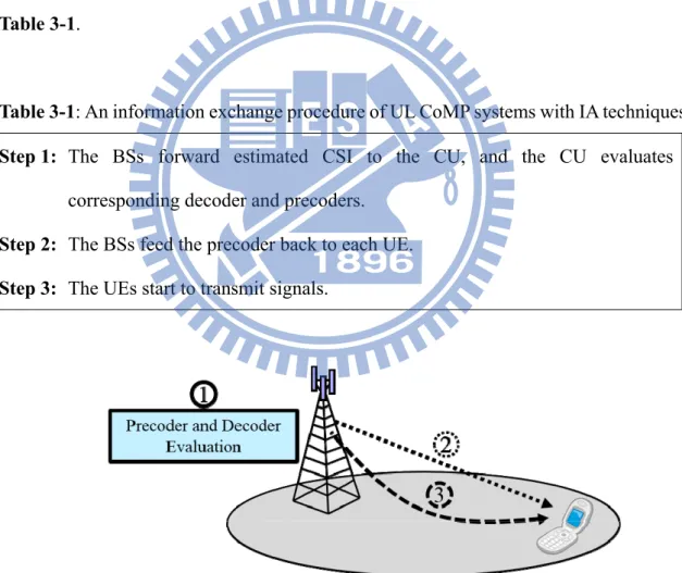
For providing more DoFs to create more reliable links, IA is incorporated into the considered centralized uplink CoMP systems. IA can be adopted in either uplink CoMP systems or downlink CoMP systems to enhance the suppression of multi-user interference. As shown in Figure 3–5 (single cell is depicted for concise presentation), to employ IA in the uplink CoMP systems, the system should operate as depicted in
Table 3-1.
Table 3-1: An information exchange procedure of UL CoMP systems with IA techniques
Step 1: The BSs forward estimated CSI to the CU, and the CU evaluates corresponding decoder and precoders.
Step 2: The BSs feed the precoder back to each UE.
Step 3: The UEs start to transmit signals.
Figure 3–5: Illustration of information exchange procedure of UL CoMP systems with IA techniques.
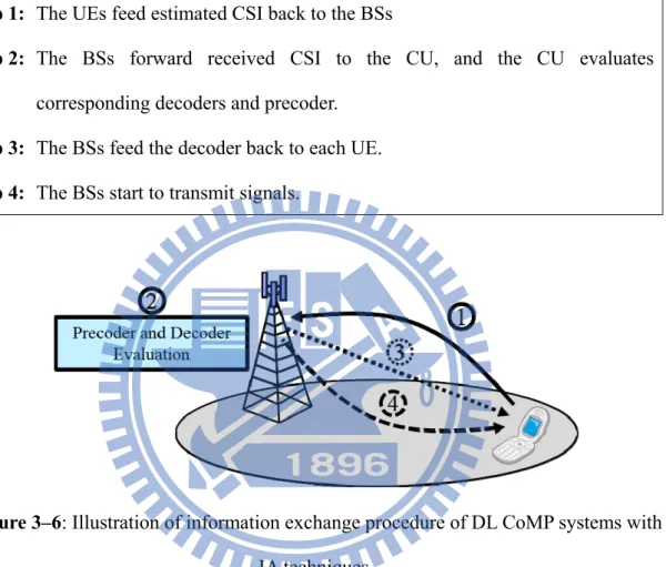
to employ IA in the downlink CoMP systems, the system should operate as depicted in
Table 3-2.
Table 3-2: An information exchange procedure of DL CoMP systems with IA techniques
Step 1: The UEs feed estimated CSI back to the BSs
Step 2: The BSs forward received CSI to the CU, and the CU evaluates corresponding decoders and precoder.
Step 3: The BSs feed the decoder back to each UE.
Step 4: The BSs start to transmit signals.
Figure 3–6: Illustration of information exchange procedure of DL CoMP systems with IA techniques.
Compared to the downlink CoMP systems, CSI feedback is not required in the uplink CoMP systems, and there is no modifications to the UEs. In this thesis, the uplink CoMP system is considered.
We here introduce the IA techniques into the interference channel model of cellular networks in the uplink CoMP scenario 3/4 involving intersite coordination between different RPs such as BSs/RRHs (i.e., the system model shown in Section 2.2), which is illustrated in Figure 3–7.
Figure 3–7: Centralized CoMP systems in heterogeneous networks.
Taking the advantages of the backhaul resource and centralized joint processing at the CU, more DoFs could be exploited for recovering the desired signals. Further, IA techniques can be incorporated to further improve the overall system throughput. According to the considered system model, the optimal design criterion of IA in the uplink CoMP systems can be described as follows [8-9]:
{ }
(
,)
,1 = ´ ," ¹ , k dk k l k H d l l d d d l k U H V 0 (3.3){ }
(
,)
, rank , , 1 æ ö÷ ç ÷= " ç ÷ çè ø k dk k H d k k k d d k U H V (3.4) where [ 1,, 2,, , , ] , ´ = T T T T Î MNr Nt l l l K lH H H H and the location index of decoding vector corresponding to the dth layer belonging to the kth UE within U is denoted as
, . 1 1 -= =
å
+ k k d i id d d The main difference between IA in the K-user interference channel and IA in the centralized CoMP system is that the latter incorporates full cooperation between BSs for computing the decoder at the CU. Because the optimal design criterion would not be feasible, two iterative algorithms proposed in [9], min-leakage and max-SINR, are adopted.
3.3.1 Min-Leakage IA in Uplink CoMP Systems
In this section, the minimum leakage IA algorithm in the K-user interference channel is modified and adopted into the considered system model. The minimum leakage algorithm in [9] can be reformulated as:
(
)
, , , , , , arg min , 1 1 = MP MP U V V Ik U V V (3.5)where Ik is the leakage of the kth UE at the output of the decoder, described as
{ }
(
,)
{ }
, , , tr , 1 1 æ ö÷ ç = ççè ÷÷ø k dk k dk k k H d d k d k d I U Q U (3.6)( )
. ¹ =å
H H k l l l l l k Q H V V H (3.7)Then, the optimal decoding matrix corresponding to kth UE
{ }
, ,1 k dk k d d U minimizing Ik can be formulated as{ }
,(
)
,1 =eig , , k dk k d k k d d U Q (3.8)where eig
(
X,i)
denotes the function of selecting eigenvectors corresponding to the 1st to ith smallest eigenvalues of X. To evaluate the precoding matrix Vk for the kth UE, Ik is reformulated by channel reciprocity [10] as follows:( )
(
)
tr , = H k k k k I V B V (3.9) where . ¹ =å
H H k k l l k l k B H U U H (3.10) The optimal decoding matrix V minimizing Ik k can be formulated as(
)
eig , , k = k k dk V Q (3.11)where k is chosen to satisfy tr
(
H)
= UPW.k k P
The iterative procedure is summarized in Table 3-3. In this thesis, the algorithm provided in this section is denoted as the “min-leakage IA”.
Table 3-3: A procedure for min-leakage IA in UL CoMP systems
Initialization: Set an initial value for decoding matrix U; we suggest adopting
partial FFT matrix as the initial point for faster convergence.
Step 1: Compute the precoders Vi, i=1,…,MP according to (3.11).
Step 2: Compute the decoder U according to (3.8).
Step 3: Go back to Step 1 till the constrained iteration number is achieved.
Step 4: Evaluate the equalizer and the achievable sum-rate according to (2.6) and
(2.7).
3.3.2 Max-SINR IA in Uplink CoMP Systems
The maximum SINR IA algorithm in the K-user interference channel is modified and adopted into the considered system model in this section. The maximum SINR algorithm in [9] can be reformulated as:
(
, , ,)
arg max, , , , , 1 1 = g MP MP U V V k d U V V (3.12)where gk d, is the SINR of the dth layer belonging to the kth UE at the output of the decoder, described as ( )
( )
( )( )
( ) ( ) ( )( )
( ) , , , , , , , g = k d k d k d k d H H d d d H d k k k k k d H d d k d U H V V H U U B U (3.13) ( )( )
( ) ( ) ( ) , , , . 0 ¹ =å
+ r H m m H k d l l l l N M l m k d N B H V V H I (3.14)Then, the optimal decoding vector (dk d,)
U maximizing gk d, can be formulated as
( ,)
(
)
( )(
)
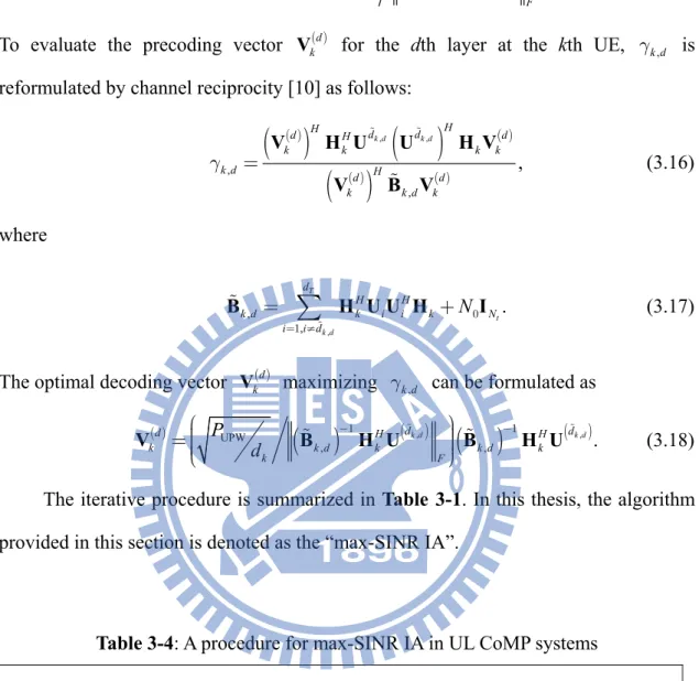
( ) , , . 1 1 - -= k d d d d k d k k k d k k F U B H V B H V (3.15)To evaluate the precoding vector Vk( )d for the dth layer at the kth UE, gk d, is reformulated by channel reciprocity [10] as follows:
( )
( )
( )
( ) ( )( )
( ) , , , , , g = k d k d H H d d d H d k k k k k d d H d k k d k V H U U H V V B V (3.16) where , , , . 0 1 = ¹ =å
+ T t k d d H H k d k i i k N i i d N B H U U H I (3.17)The optimal decoding vector Vk( )d maximizing gk d, can be formulated as
( ) UPW
(
)
( ,)(
)
( , ) , , . 1 1 - -æ ö÷ ç =çç ÷÷÷ çè ø dk d dk d d H H k k d k k d k k F P d V B H U B H U (3.18)The iterative procedure is summarized in Table 3-1. In this thesis, the algorithm provided in this section is denoted as the “max-SINR IA”.
Table 3-4: A procedure for max-SINR IA in UL CoMP systems
Initialization: Set an initial value for decoding matrix U; we suggest adopting
partial FFT matrix as the initial point for faster convergence.
Step 1: Compute the precoders Vi, i=1,…,MP according to (3.18).
Step 2: Compute the decoder U according to (3.15).
Step 3: Go back to Step 1 till the constrained iteration number is achieved.
Step 4: Evaluate the equalizer and the achievable sum-rate according to (2.6) and
3.4 Computer Simulations
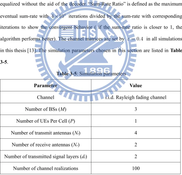
The convergence behavior and sum-rate performance evaluations are presented for the comparison between the uplink CoMP transceiver scheme assisted with and without IA. In the following simulation results, “min-Leakage IA” and “max-SINR IA” represents the algorithms shown in Section 3.3.1 and Section 3.3.2. The achievable sum-rate is calculated based on (2.7) because a linear MMSE receiver is adopted in our work. In this thesis, “CoMP without IA” represents the approach that the precoder of each UE is formed by columns of identity matrix, and the received signal is directly equalized without the aid of the decoder. “Sum-Rate Ratio” is defined as the maximum eventual sum-rate with 4
4 10´ iterations divided by the sum-rate with corresponding iterations to show the convergent behavior ( if the sum-rate ratio is closer to 1, the algorithm performs better). The channel matrices are set by e= 0.4 in all simulations in this thesis [13]. The simulation parameters chosen in this section are listed in Table
3-5.
Table 3-5: Simulation parameters
Parameter Value
Channel i.i.d. Rayleigh fading channel
Number of BSs (M) 3 Number of UEs Per Cell (P) 1
Number of transmit antennas (Nt) 4
Number of receive antennas (Nr) 2
Number of transmitted signal layers (di) 2
Number of channel realizations 100
IA algorithm has superior convergence rate in comparison with the max-SINR IA algorithm; however, the min-leakage IA algorithm converges to bad performance. From the observation, the max-SINR IA algorithm has nearly no sum-rate enhancement with more than 4 10´ 4 iterations. Therefore, the convergence condition is defined to be with
a slight 3% sum-rate degradation compared with the sum-rate with 4
4 10´ iterations. Secondly, the average achievable sum-rates of different algorithms in convergence are shown in Figure 3–9. The results are observed as follows. Because the min-leakage IA algorithm only tries to suppress interference, desired signals might be suppressed simultaneously. The min-leakage IA algorithm performs worse than the max-SINR IA algorithm and the CoMP without IA. With enough iterations (8000 iterations), the max-SINR IA algorithm has superior performance in the comparison with the CoMP without IA; however, with insufficient iterations, the max-SINR IA performs nearly the same as the CoMP without IA.
From the above simulation results, incorporating IA into uplink CoMP systems is shown to achieve the promising performance in mitigating severe interference. However, tremendous number of iterations are required for better performance. In the next section, two algorithms will be proposed to boost the convergence rate.
100 101 102 103 104 1 1.05 1.1 1.15 1.2 1.25 1.3 1.35 1.4 Number of Iterations S um -R ate R ati o Min-Leakage IA (30 dB) Min-Leakage IA (40 dB) Max-SINR IA (30 dB) Max-SINR IA (40 dB)
Figure 3–8: Convergence behavior of max-SINR IA and min-leakage IA in UL CoMP
10 15 20 25 30 35 40 0 10 20 30 40 50 60 70 80 90 Tx Power [dB] S um -R at e [ bps /H z] Max-SINR IA (8000 iterations) Max-SINR IA (5 iterations) CoMP without IA Min-Leakage IA (5 iterations)
Figure 3–9: Sum-rate performance of CoMP without IA, max-SINR IA, and
min-leakage IA in uplink CoMP systems with 5 and 8000 iterations.
3.5 Summary
Interference alignment aided uplink CoMP is discussed and evaluated in this chapter. First, two popular interference alignment algorithms (i.e., min-leakage IA and max-SINR IA) [8-9], developed in the K-user interference channel are incorporated in the uplink CoMP transceiver design. Their sum-rate performance is evaluated, and it is demonstrated that the max-SINR IA algorithm has better sum-rate performance because of a good compromise between interference and received power of the desired signal. Hence the max-SINR IA algorithm is regarded as a highly potential interference mitigation scheme. According to the observation, numerous iterations are required to guarantee that the max-SINR IA algorithm converges. In the next chapter, two IA algorithms are proposed to boost the convergence rate of IA for making IA easier to be implemented.
Chapter 4
Proposed Efficient Interference
Alignment in Uplink CoMP Systems
In Chapter 3, the max-SINR IA algorithm is considered as a candidate for uplink CoMP. However, it is found that numerous iterations are required to achieve the improved sum-rate performance. As a remedy, two new IA aided transceiver designs are proposed. One is to use the BQRD to eliminate the interdependency of precoders among UEs through the SIC technique. Due to interference pre-subtraction, it is expected that the proposed BQRD aided IA has a faster convergence rate. The other one, called the “two-stage IA”, is to directly optimize the structure of the effective channel defined in (2.4) and employ power loading. Different from previous numerical methods (e.g., the max-SINR IA algorithm proposed in Section 3.3.2), it is expected that the two-stage IA algorithm converges more quickly because the two-stage IA algorithm aims to get the characteristic of the effective channel in convergence. Due to the MAC-like nature of uplink CoMP, the iterative procedures of evaluating IA solutions are developed by exploiting the duality between multiple access and broadcast channels. [20-21].
The organization of this chapter is shown below. The motivation of the proposed IA aided UL CoMP transceiver schemes is given in Section 4.1. In Section 4.2, the proposed BQRD aided IA algorithm and its associated computer simulations are presented. To further minimize the performance gap at low SNR, a two-stage IA
algorithm is proposed to directly optimize the effective channel in Section 4.3. Then, the computational complexity of the two proposed transceiver schemes is analyzed in Section 4.4. Numerical simulation results including the convergence behavior and sum-rate performance are given in Section 4.5 to compare the merits and drawbacks of the two proposed transceiver schemes. Finally, this chapter is summarized in Section 4.6.
4.1 Motivation
To achieve a higher system capacity in an interference limited communication environment, many techniques have been developed to cope with interference. Uplink CoMP is one of the techniques that aim to manage the interference caused by the UEs in other cells. To obtain the available DoFs that can be provided by the centralized uplink CoMP systems, a recently proposed technique (i.e., the max-SINR IA algorithm) is suggested to provide more DoFs in Section 3.3.2.
However, numerous iterations are required to guarantee that the max-SINR IA algorithm converges, which makes IA difficult to be implemented. From our observations, one of the reasons is the interdependency between UEs in multi-cell joint transmission scenarios. In Section 4.2, the proposed BQRD aided IA algorithm attempts to eliminate this interdependency to boost the convergence rate. Next, from the observation of [15], the SINR can be improved through proper power allocation if the effective channel has the nearly diagonal structure leading to less interference. Based on this idea, we further propose a two-stage IA algorithm to optimize the effective channel by mitigating different kinds of interference separately.
4.2 Proposed Block QR Decomposition Aided IA
Algorithm
In this section, an efficient IA aided transceiver design algorithm for uplink CoMP systems is proposed to mitigate interference. The BQRD is used to resolve the interdependency of precoders among user UEs through the SIC technique. To further improve the efficiency, an additional constraint is employed by a projection operation. In the following paragraphs, the detailed algorithm is depicted in Section 4.2.1. Then, some computer simulation are shown to confirm the performance and convergence rate in Section 4.2.2.
4.2.1 Proposed Algorithm
In this section, a new IA algorithm is proposed to pursue maximum sum-rate with small number of algorithmic iterations. The optimization problem is formulated as follows: ( ) sum UPW T subject to , , , . 1 , , , 2 2 max 1, , 1 1, , MP l F i F R P l MP i d = = = = U V V V U (4.1)
We consider the possibility to reduce iterations if the interdependency between UEs can be eliminated.
Firstly, performing the BQRD [1] to the channel matrix HÎMNr´MPNt
produces
, =
H QR (4.2)
where QÎN M N Mr ´ r is an unitary matrix, and R is a
r t
triangular matrix partitioned into sub-matrices , (N P Nr ) t, i j ´ Î R so that ( ) , r t i j = N P N´
R 0 for i > j. Second, by incorporating (4.2) with (2.8), the corresponding approximated SINRk,d value for each data layer can be evaluated as follows [16]:
( )
(
)
(
( ))
SINR 1 metric , , , , H d d k d k k k d k k k d -» R V C R V = (4.3) where{ }
( )1 1 t t kN k = k- N+R R and Ck d, is the interference-plus-noise covariance matrix of
dth layer belonging to the kth UE as
( )
(
)
(
( ))
( ) ( ) . , 0 , , r H m m k d l l l l N M l m k d N ¹ =å
+ C R V R V I (4.4)Next, the optimization problem of maximizing the achievable sum-rate can be approximated by minimizing the summation of the reciprocal of individual
(
metric ,)
, ln 1+ k d expressed as(
)
( ) ( ) sum metric metric metric . 2 , , 1 1 1 1 2 , 1 1 log 1 ln 1max max log 1
max min k d d MP k MP k k d k d k d k d d MP k d k d R e = = e = = = = é + ù - é + ù ê ú ê ú ë û ë û é ù » êë + úû åå åå = =
åå
(4.5)Then, when the metrick,d is larger than
(
e -1)
for data decoding, which is oftensatisfied in many practical scenarios, the problem in (4.1) can be approximated as
( metric ) sum , 1 1 , 1 ln 1 max min d MP k k d k d R e b a = = æ ö÷ ç ÷ ç ÷ ç - ÷ ç ÷ ç ⋅ + ÷ ç ÷÷ çè ø åå » (4.6)
where a and b are constants obtained by MMSE criterion within specific region but the values are invariant to the optimization problem. Next, the original optimization solution of (4.1) can be approximated as
(
)
sum .
metric
1 1 ,
1 arg max arg min
ln 1 k d MP k d k d R = = » +
åå
(4.7)When the algorithm goes from k =MP to k =1, on the right-hand side of (4.7), the first group (k =MP) is affected only by VMP, and the second group
(k =MP- is affected only by 1) VMP and VMP-1, etc. The recursive dependency is the direct consequence of the block-wise upper triangular structure R. This is equivalent to the scenario where interference caused by the UE with lower index is pre-cancelled.
For further improving the sum-rate performance, we attempt to modify the decoding matrix ˆU obtained by pursuing the sum-rate according to (3.15). From the
observation of [15], the sum-rate could be improved if the effective channel has the nearly diagonal structure which leads to less interference. By the following derivation, the effective channel with the aforementioned structure can be obtained in terms of R:
(
)
eff , H H H H H = = = = H U HV U QRV Q U RV U RV (4.8) where U and U=Q U are the final decoding matrix and the pre-projected Hdecoding matrix, respectively. Here the column vectors of U are set to be in the subspace S spanned by the left singular vectors of R corresponding to the 1st to dTth largest singular values of R. For reducing additional complexity, a matrix
r r
N M N M´
Î
M is designed to evaluate U as:
. ˆ =
U MU (4.9)
To satisfy such constraints, all column vectors of ˆU are further projected into the
subspace S, and M can be expressed as:
,
H
=
M TT (4.10) where TÎN M dr ´T is formed by the left singular vectors of R corresponding to the
1st to dTth largest singular values of R. Finally, the eventual decoding matrix is reconstructed as
.
=
U QU (4.11)
The iterative procedure is summarized in Table 4-1. In this thesis, the algorithm provided in this section is denoted as the “BQRD aided IA”.
By introducing the BQRD technique, the criterion in (4.1) can be reformulated to a form similar to the SIC technique in signal detection. It is expected that the algorithm converges more quickly and has better performance in severely interfering scenarios due to interference pre-subtraction. We further force the decoding vectors to satisfy the convergence condition with just one more step to project them into the selected subspace. By appropriately constructing S, the convergence rate could be significantly improved with only slight performance degradation.
Table 4-1: A procedure for BQRD aided IA in UL CoMP systems
Initialization: Set the decoding matrix U to be part of FFT matrix.
Step 1: Perform the BQRD to obtain the unitary matrix Q and the block upper triangular matrix R.
Step 2: Compute the precoders Vi from i=MP to 1 according to (3.18) by viewing R as the channel matrix.
Step 3: Compute the decoder U according to (4.9) by viewing R as the channel matrix.
Step 4: Go back to step 2 till the constrained iteration time is achieved.
Step 5: Obtain the final decoder U according to (4.11).
Step 6: Evaluate the equalizer and the achievable sum-rate according to (2.6) and (2.7).
4.2.2 Computer Simulations
This section shows simulations for the convergence behavior and achievable sum-rate performance of the proposed algorithm and compares the results with different CoMP algorithms. In the following simulations, “max-SINR IA” and “BQRD aided IA” stand for the algorithms presented in Section 3.3.2 and Section 4.2.1, respectively. From observations, both the max-SINR IA and BQRD aided IA have nearly no improvements with iterations larger than 4 10´ 4. Therefore, the
convergence condition is defined at the iterations of 3% degradation compared with the performance at 4 10´ 4 iterations for all simulation cases. The performance are
evaluated in 3 scenarios (i.e. the scenario adopted in Section 3.4, typical CoMP scenario, and large CoMP size scenario). The simulation parameters chosen for typical CoMP scenario and large CoMP size scenario are listed in Table 4-2 and Table 4-3, respectively.
Table 4-2: Simulation parameters for typical CoMP scenario
Parameter Value
Channel i.i.d. Rayleigh fading channel
Number of BSs (M) 3 Number of UEs Per Cell (P) 1
Number of transmit antennas (Nt) 4
Number of receive antennas (Nr) 4
Number of transmitted signal layers (di) 3