Active dual-beam aperture-coupled leaky-
wave antenna
Chien-Jen Wang, Nien-An
Kao,
C.F. Jou and Jin-Jei WuAn active aperture-coupled leaky-wave antenna (LWA) with excellent dual-beam scanning capability is presented. An X-band varactor-tuned HEMT VCO is integrated on the other plane through an aperture with the LWA. This antenna has the advantages of multi-functionability, interference shielding, and a scanning main beam. The measured main beam in the elevation plane can be continuously scanned for 20" for each beam as the HEMT VCO frequency is vaned from 8.97 to 9.5GHz. An effective isotropic radiation power of 18.89dBm for the right beam and 19.06dBm for the left beam is achieved.
Introduction. Recently, leaky-wave antennas (LWAs) have become popular, and there is a growing interest in the use of various types of leaky-wave antennas as frequency-scanning elements [ 1, 21. Leaky-wave antennas possess the advantages of a low profile, fab- rication simplicity, ease of matching, a narrow beamwidth and fre- quency-scanning capability. The aperture-fed structure was proposed by Pozar [3] in 1985, and provides the advantages of low cost and compact size, and avoids interference between the active network and the radiation element. Hence, the design of leaky- wave antennas with an aperture-fed structure will be a new topic of research in the future.
In the study presented in this Letter, we have integrated the active circuit with a centre-fed aperture-fed LWA and produced a dual-beam radiation pattern. Since the HEMT VCO IS placed below the antenna, the whole sue can be reduced. The existing ground plane decreases the inference between the antenna and the VCO. The charactenstics of this dual-beam scanning LWA will be of great use in mobile communication and automotive radar sys- tems. To suppress the dominant mode, we have added a sequence of covered wires to the centre of the microstrip LWA.
L _ _ - - - _ _ . . _ _ - - -
HEMT VCO
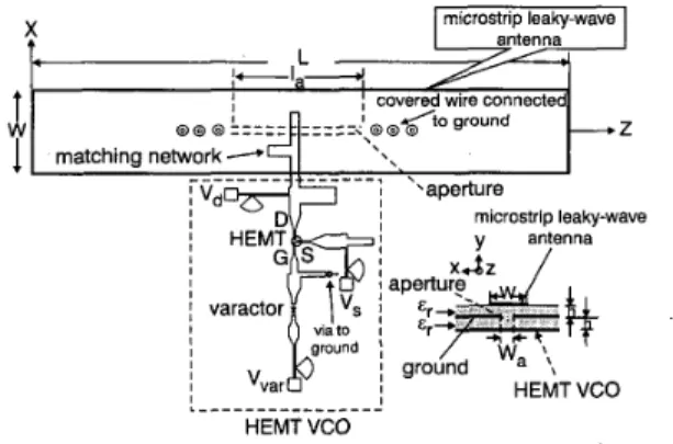
1255111 Fig. 1 Configuration of X-band active aperture-coupled dual-beam leaky-wave antenna
L = 125cm, W = l.lcm, E, = 2.2, h = 0.508mm, 1, = 30mm, W, =
1.8mm, V , = 2 04V, and V , = OV
t Y
injection from centre
125612/
X
J
Fig. 2 Geometry and co-ordinate system for proposed lenky-wave antenna
Design: Fig. 1 shows the configuration of an X-band active aper- ture-coupled dual-beam LWA. An LWA is placed on one sub- strate, which is coupled to an HEMT VCO feed on another parallel substrate. We utilised a centre-fed aperture in the ground plane, which separates the two substrates, to couple the signal and produce a dual-beam radiation pattern. The RTDuriod substrate used is 0.508mm thick with a dielectric constant of E, = 2.2. The VCO was designed using a small-signal iterative procedure. An NEC NE42484C low-noise HEMT is used as the active device and the drain is biased at 2.04V. The tuning element is the ALPHA DVG6064-11 GaAs package varactor. The aperture was placed above the open-end microstrip lines and located at the centre of the LWA. Its optimal width is -l/lOkz when the aperture length was chosen to be 3cm.
The geometry and co-ordinate system for this leaky-wave antenna are shown in Fig. 2. Each slot radiates the same field as the magn2tic dipole [l, 41 with the equkalent magnetic current density MRS for the right injection and MLs for the left injection.
The width Wand length L of the radiating element are empirically chosen to be 1.1 and 12.5cm, respectively.
-..-.;7..r ,._. I ' ' I ' '
frequency, GHz
Fig. 3 Normalised complex propagution constants and measured return loss against operating frequency
ko is free-space wavenumber , , , ,
,
, , , , 0 k.. -50 7 8 9 10 11 12 13 1256/3/ IS111 d k 0W O
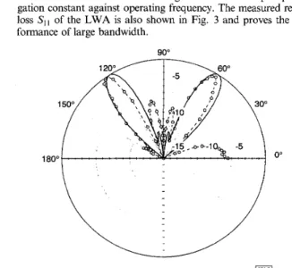
~ _ _ _ 90"Fig. 4 Experimental result of H-plane frequency-scanning radiation pat- tern
8.97GHz
9.5GHz
Theoretical and experimental results: Employing the rigorous (Wiener-Hop0 solution in [5], we can obtain the normalised com- plex propagation constant plk0 - j d k o of the frst higher-order mode, where plko is the normalised phase constant and d k o is the
normalised attenuation constant. Fig. 3 shows the complex propa- gation constant against operating frequency. The measured return loss SI, of the LWA is also shown in Fig. 3 and proves the per- formance of large bandwidth.
900
0”
Fig. 5 Comparison of theoretical and measured radiation patterns of active L W A at 8.97GHz
-0- measured theory
Adjusting the DC bias of the varactor from 1 to 15V, we can tune the operating frequency of the HEMT VCO from 8.97 to 9.5GHz and change the dual-beam position in the elevation plane. Fig. 4 shows the experimental result of the H-plane radiation pat- tern for the active dual-beam aperture-coupled LWA. It shows that the scanning angle is steered over a range of 20” for each beam. Under the far field condition, the maximum effective iso- tropic radiation powers (EIRPs) of this antenna are 18.56 f 0.33dBm for the right beam and 18.9 k 0.13dBm for the left beam in the frequency range 8.97-9.5GHz. Since this design uses the centre-fed structure, the back lobe is successfully veiled by the opposite main beam of this LWA. Fig. 5 shows the comparison of the theoretical and measured radiation patterns of the active LWA at 8.97GHz. These results agree reasonably well.
Conclusions; An active dual-beam aperture-coupled leaky-wave antenna has been described in this Letter. The centre-fed structure has been shown to be a viable method for exciting the leaky mode. This antenna creates a dual-beam scanning capability and pro- vides excellent shielding to eliminate the interference of the HEMT VCO and the antenna. It is very suitable for automotive radar sys- tems, modulated communication links, and other area communi- cation applications.
0 IEE 1999
Electronics Letters Online No: 19991376 D 01: 10. I049/el: I9991 3 76
Chien-Jen Wang, Nien-An Kao and C.F. Jou (Institute of Communication Engineering, National Chiao-Tung University, Hsinchu, Taiwan. Republic of China)
Jin-Jei Wu (Electric Engineering Department, Kao Yuan College of Technology and Commerce, Kaohsiung, Taiwan, Republic of China)
10 September 1999
References
1 JOU, G.J., and TZUANG, c.K.: ‘Oscillator-type active-integrated antenna: The leaky-mode approach’, IEEE Trans. Microw. Theory Tech., 1996, MTT-44, pp. 2265-2272
2 WANG, c.J., IOU, c.F., and wu, J.J.: ‘A novel two-beam scanning active leaky-wave antenna’, IEEE Trans. Antennas Propag., 1999, 3 POZAR, D.M.: ‘A microstrip antenna aperture coupled to a
microstripline’, Electron. Lett., 1985, 21, pp. 49-50
4 BALANIS, C.A.: ‘Antenna theory analysis and design’ (Wiley, New York, 1997), 2nd edn.
CHANG, D.C., and KUESTER, E.F.: ‘Total and partial reflection from the end of a parallel-plate waveguide with an extended dielectric loading’, Radio Sci.. 1981, 16, pp. 1-13
AP-47, (8), pp. 13141317
5
Coaxial-feed axial mode hemispherical
helical antenna
H.T.
Hui, K.Y.
Chan,E.K.N.
Yung andX.Q.
Shing A coaxial-feed axial mode hemispherical helical antenna is studied experimentally and theoretically. Results for a 3-turn hemispherical helix indicate that circular polarisation can be obtained over a broad beamwidth. The gain bandwidth is -33% and the peak gain is 7.6dB. The input impedance shows that it is a standing wave antenna.Introduction: The wideband, high gain, and circular polarisation characteristics of conventional cylindrical helical antennas have been extensively studied in the past few decades [l, 21. More
recently, a spherical helical antenna was suggested [3] and investi- gation results indicated that spherical helical antennas can provide circular polarisation over a wide beamwidth. The radiation pat- terns are free from sidelobes and the backlobe levels are very low. Moreover, a high gain of -9.5dB can be achieved with a 10-turn spherical helix. These are very significant differences from conven- tional cylindrical helical antennas [ 11. However, spherical helical antennas, like cylindrical helical antennas, are difficult to maintain in a vertical position over a flat ground plane. In this Letter, we study a hemispherical helical antenna that overcomes this prob- lem. Unlike spherical helical antennas, hemispherical antennas are only half as high. By winding the helix on the surface of a polysty- rene hemisphere, this antenna can rest very steadily on the ground plane. In our theoretical and experimental studies, we found that the performance of this antenna is similar to that of a spherical helical antenna. Owing to its more robust structure and no- sidelobe patterns, we believe that this antenna will be very useful for array constructions.
c
<
i
, h ,1 I
lcoaxiai cable 1710111Fig. 1 Hemispherical helical antenna
Antenna geometry: The geometry of the hemispherical helical antenna is shown in Fig. 1. The curved portion of the thin wire is described by the following equation in the spherical co-ordinate system proposed by Cardoso and Safaai-Jazi [4]:
r = a ( 2 )
where a is the radius of the hemisphere and N is a number equal
to twice the number of turns of the helix. Note that eqn. 1 describes only a right-handed helix. For a left-handed helix, the sign of the expression inside the bracket in eqn. 1 should be reversed. The length of the straight wire leading from the coaxial opening to the hemispherical helix is denoted by h. The radius of
the wire is r, and is equal to the radius of the inner conductor of the coaxial line. The radius of the outer conductor of the coaxial line is b. The hemispherical helix is wound on the surface of a pol-
ystyrene hemisphere and is connected to the coaxial line at the periphery of the hemisphere.
Experimental and theoretical results: This antenna was studied both experimentally and theoretically and results are mainly pre- sented for a 3-turn hemispherical helix. The moment method