Design of
A
MIMO OFDM Baseband
Transceiver
for Cognitive Radio System
Jui-Ping Lien, Po-An Chen and Tzi-Dar Chiueh Graduate Institute ofElectronics Engineering and
Department ofElectrical Engineering, National Taiwan University, Taipei, Taiwan
Email: pa@analog.ee.ntu.edu.tw
Abstract- As wireless communication services become more use of spectrum, the CR system needs to adapt its band-prevalent, bandwidth requirement increases dramatically. As width, carrier frequency and spectrum allocation to avoid such, the concept ofCognitive Radio (CR) has recently received systemmalfunction. Inthe
proposed
CR system, theoperating
much attention. In this paper, we present aMIMO-OFDM based
stem
ion. In
thesystem, the opEri
CRsystem capable ofdynamically adjusting its system parame- frequency
ils
5GHzUNII
band, the same as that of IEEE ters according to spectrum allocation. From system simulation, 802.1la wireless system. The targeted 5GHz UNJI band can theproposed transceiver isshownto be apromising solutionfor be divided into lower band, 5.15 - 5.35GHz, and upper band, CRapplications. 5.725-5.825GHz, and our system will use either one of them according to the overall system requirements. Based on theI. INTRODUCTION above system requirements and OFDM design considerations, Recently, wireless communication is becoming pervasive. we define the overall system specifications.
The available spectrum, however, is getting scarce and the
conventional fixed spectrum allocation and usage has now A. System Specification become inefficient [1]. Cognitive Radio (CR) is proposed
and widely discussed to solve this dilemma [2]. The basic Summary of the major specification is shown in Table I,
idea of CR is to provide a system with the ability to sense manifesting the flexibility of the proposed system. The basic
available spectrum slots not occupied by existing users and parameter setting is from that of IEEE
802.11a,
bearing thedetect whether any primary useris demanding the bands that OFDM symbol duration of 4-,us, resulting from the sum of
the CR system currently uses. In 2003, a regulation enacted FFT and guard interval (GI) period. Since one subband is
byFCC formally initialized the commercialization of CR [3]. 20MHz and the possible number of subband allocation is
Currently, CR plays a major role in many applications to 1, 2, 4 or 8, we can get the corresponding bandwidths. As
enhance communicationperformance and/or provideadvanced sampling rate is the sameas bandwidth, differentFFT lengths
services [4]. Since CR only uses non-contiguous bands in can be obtained. The number of subcarrier used is less than
the spectrum, Orthogonal Frequency Division Multiplexing the corresponding FFT lengths since there are guard bands
(OFDM) is considered a suitable transmission technique. In to avoid out-of-band interference. Finally, to provide multiple brief, the primary target of CR is to find out available bands data rate, V-BLAST 2 x 2 MIMO scheme is implemented [5].
and change, if necessary, system parameters such as carrier
frequency, transmission bandwidth, power consumption and TABLEI
SYSTEM SPECIFICATIONS
modulationtype to achieveefficientuse of spectrum resource.
Inthis paper, a MIMO-OFDM CR system for 5GHz UNII Lower band Upper band
band to coexist with IEEE 802.11a Primary Users (PU) is Frequency band(GHz) 5.15-5.35 5.725-5.825
proposed.
Theproposed
system
can sensethechannel charac-Subband
Number 8 4teristics to actively modify its physical layer settings through FFTLength
64/128/256/5812
64/128/256 parameterized designsothat existing PU are notinterfered by Subcarrier Used 52-500 52-244theCR signals. SubcarrierSpacing 312.5KHz
The rest of thepaper is organized as follows. In Section 2, FFTPeriod
302us
thesystemspecification and channel model will be introduced.The design of the transceiver is discussed in Section 3. In
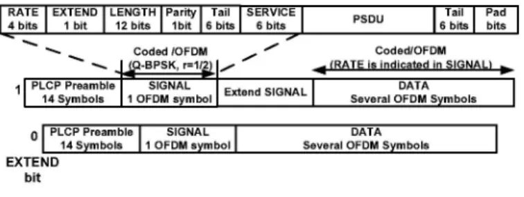
Section4, simulation of the CR system will be given. Finally, The packet format of the system is devised as shown in
Section 5 concludes this paper. Figure 1. There are 14 symbols in preamble, including 10 short and 4 long preamble. In order to support adaptivemodulation,
II. SYSTEM SPECIFICATION AND CHANNEL MODEL we design a
1-bit
EXTEND bit; when set to 1, itinforms thatThere are two basic considerations in the overall physical there is an extra extended field containing more parameters
layer specification design: dynamic spectrum allocation and about the packet. Also, when the system is operating as an
channel characteristic. As the primary users change their MIMO transceiver, Alamouti code [6] is adopted in the long
preamble pattern transmitted by two antennas to estimate B. Receiver
channel frequency response. The receiver can be partitioned into three parts: initial
syn-chronization, CFO and SCO tracking loops, channelestimation
RATE EXTEND LENGTH Parity Tail ISERVICE PSDU Tail
I
Pad as well as data recovery, which also represents the operation4bits II bit 122bits 1Ibit 16bits 6 bits I6bitsl bits Ircvr,rpeet
_Coded/IOFDM Coded/OFDM flow of the receiver. The proposed receiver architecture and
,.
VQ-BPSK,
r=112) (RATE is indicated inSIGNAL) initial synchronization flow are depicted in Figures 3 and 4,PLCP Preamble SIGNAL SIGNAL DATA .t . .
114Symbols 1OFDM symbol Extend Several OFDM Symbols respectvely. Since OFDM system iS very sensitve to tming
____I__PLCP ____Preamble______SIGNAL_____DATA__
andfrequency deviation, thesystembegins synchronization byoPLCPPreamble SIGNAL DATAshrprabe dlycreaon stme
14Symbols 1OFDMsymbolI Several OFDMSymbols
computing
shortpreamble (SP) delay
correlation to estimateEXTEND coarse symbol timing and coarse CFO. From Figure 4, with
bit
the autocorrelation property of SP, the coarse CFO can be
Fig. 1. Packet Format. estimated from the peak position of delay correlation in step 2 while the coarse symbol timing can be predicted from the position of the half peak value found in step 3. Similarly, the
B. Channel Model
long preamble
(LP)
,passed
into matchedfilter,
offers themechanism to find fine symbol timing by firstly getting the The channel model used for simulation is based on IEEE peak position of matched filter output as in step 5 and trace 802.11 TGn standard, which stipulates 6 different MIMO back in time until seeing a strong enough multipath component
channelmodels, representing various indoor environments [7]. to determine the window containing maximum energy as in
Based on these MIMO channels, we construct the equivalent step 6. Lastly, fine CFO estimation can be performed by
baseband channel modelby adding multipath Rayleigh fading, observing delay correlation result from LP, depicted in step
additive white gaussian noise (AWGN) , carrier frequency 7.
offset (CFO) and sampling clock offset (SCO) . To speed up Time Domain Frequency Domain
thesimulationprocess, we propose anapproach that considers [d 'L>
the
interpolation
needed inmodeling multipath
and SCO I CF FFTBlock sco Channel1> * 1> 1> 1 * 1 1> 1 DerotatorI1TltTC1~~~~~~~~~~D (64/128/ Compensation «lfiEstimation
effects at the same time, which also gives a closer channel
InDot
(26/512
t) Etmio emulation to the real environments. CoarseSymbol|EtCFO
Estimation|s|t||mato
|0 Processing |III. PARAMETERIZED TRANSCEIVER DESIGN Delay Integrator LowPass
E||
stimaton Tiino | Fl Modification ||A. Transmitter
The 2 x 2 MIMO-OFDM transmitter block
diagram
isX
---showninFigure 2. The binary data streamfirstpassesthrough SynchronizationSynchronization Tracking Loop
~~~~Channel
Data RecoveEstimation 2constellationmapperaccordingtothe modulationtypes.
After-wards, the data stream is allocated to the corresponding data Fig. 3. Blockdiagramof the baseband CRReceiver. subcarrier positions and then sentinto the IFFT block, where
preamble is inserted. Finally, the GI is added to complete Used for signal Usable
the generation of the time-domain transmitted signal. The detection, AGC 1 Short Preamble Long Preamble 1
baseband
signal
is then
up-converted and sent out through the
N/4|N/4|N/4|N/4|N/4|N/4|N/4|N/4|N/4|N/4 Gl2
N
N
transmitting antennas.
1.SPmovingaveraged 5. PeakPositionof 7.FineestimatedCFO
delay correlation Match Filter found beLPdelaycorrelation
spectrumallocation
informatIn-X
I ±1" @ oX _ 3. Halfpeakpeak
| I ~~~~~Insert'Insert ' X i* _H4 @ ,' value found
Preamble
input bit
stream1 @ lConstellation > Symbol 2.IFFT ;>OInsertGI 2* Peak positionfound. 4.Derotatesignal with 6.Find the window g|Mapping | | Shaping | x (64112812561612pt) Insert GIloc1u CoarseCFO estimated coarse estimated CFO containing
* W --W--- .... ;;;;-;;F;-E;;;;--;;;;;EE;oup- maximum energy
ConstellationiiSym1bol IFFT iInsertG
Mapping
Shaping
)-3
Ij(64112812512pt)
5
setG
Fig.
4.
Operation
flow of the
proposed
receiver.
i;uput
modu~~~tion Insert When the system completes initial synchronization, it then
type
LPeablpl
InnerTransmitter
enters into tracking mode. As shown in Figure 3, SCOcompensation, JWLS estimator [8], low pass filter, NCO form Fig. 2. Block diagram of the baseband CR transmitter. the feedback path to control CFO derotator. And the scaling block, integrator, FFT window try to set the proper FFT timing 4099
boundary so as to keep track of the SCO. In the mean time, TABLEII
ADPIESYSTEMPARAMETERS.
the channel estimation,
phase
modification
andslicer
start torecoverthe received data. Fromsimulation result, theaccuracy Coarse Symbol Timing Synchronization
of estimated channelfrequencyresponsedegrades moreunder Matched Filter lower SNR condition. As channel estimation is pivotal to the FFT BlockJWLS entire data recovery flow, we then smooth acquired channel SCO Compensation
frequency response through raised cosine filter, of which the Channel Estimation
time domain response is: Phase ModificationEqualization
if 0 < ltl <
1-OT
Slicer(1 +COS
(|t-1
T)) if 12T
<Itl
<I0T
t0 elsewhere. correlation result to estimate the SNR value [9]. Meanwhile,
Thus, the frequency domain filtering function for smoothing matched filter is used tocomputethe channelimpulseresponse
is: forestimatingchanneldelay spread.Hardwaresharing concept
X(f) =sinc(fT)
cos(7/3f
T) is realizedby reusing
thedelay
correlation and matched filter1
-4f
T circuits,which
are also neededduring
initial
synchronization.
where Q is the roll-offfactor, and T is the width of the time
IV.
SIMULATION RESULTdomain window, the length of which is chosen to be that
ofguard interval because the maximum interval of statistical A System Verifcation
delay spread profile is less than the duration of GI. To
verify
the correctness of theproposed
system, webuild Lastly, V-BLAST processing for equalization and detection a functional simulation model for our system to compare can further enhance data rate and lower bit error rate when ourdesign
with theoreticalperformance.
Hence, we set the MIMO is applied. The linear combinational nulling concept receiver under SISO mode withperfect
channelestimation,
is adopted for the detection of V-BLAST scheme, which is timing synchronizationand AWGNonlychannelenvironment, outlined as follows: which enables us to
plot packet
error rate(PER)
to see ifStep 1: Determine the optimal detection order of received thesystemperformancemeetstherequirements from 802.1 la.
signal.
Figure
5 shows that the PER curves of all four modulationsStep 2: Suppose the determined detection order is coincide with those obtained from theoretical
analysis,
indi-ki, k2,
... cating competitiveness of the proposed receiver.Wethenpick the firststream astarget signalwhile treat other PakcetError Rate(PER) - AnalyticBPSK
streams as interference, which are later canceled
by
using
using Analyti~~~~~~~~~~~~~~~~Analytic
16QAMproper weights
and vectormultiplication
so as toget
the0.9
Analytic---640M-
---
t---
---
AnatedBPSI<M
0 Simulated BPSK
detected first stream. 0.8- - --- --- SimulatedQPSK
Step
3: Subtract all theremaining
streamsby
the detected 0 Simulated64QAM
value we get in Step 2, then return to Step 1, continuing 0.6
-iteration of the above stepsuntil we detect all streams.
C.
Parameterized Design
QPSK
16--QA-M
:64-QAM
Torealize aCR system, theproposed transceiver is capable BPS of adjusting the parameters of certain functional blocks as
the channel changes its characteristics. Table II lists those [[2 , ---_
receiver functional blocks in which some circuit parameters o.
1-will be
adjusted according
tothe channelconditions;themajor
o T111lcriterion is the FFT size, which can be obtained through the
SNR
persymb 25informationprovided by the sensing block. The capability of dynamically adjustingtheseparametersindicates theprofound
reconfigurability of our system, meeting the demand for CR Fig.5. Packet error rate(PER) comparison. system.
D. Sensing block B. Simulation with/without CFO and SCO
Another major CR system requirement is the ability to as- The bit error rate (BER) comparisons between the two cases sess the characteristics or quality of the channel. In our system, of no CFO/SCO and CFO/SCO with compensation are shown we realize two functions: SNR estimation and delay spread in Figure 6. Under different types of channel, we can see the estimation, as shown in Figure 3. We use short preamble delay BER performance in the case with SCO = 13.7ppm, CFO
=0.254 Af and
compensation
for both is very close to 1 UncodedBERComparison(QPSK)the no CFOISCO case. The simulation result
using
64QAM
Channel ModelBunder channel model B, D, and B demonstrates the
system's
Channel..ChannelModel....DModel E effectiveness incompensating
SCO and CFO effects.Uncoded BERComparison (64-QAM):_________________________________________with &w/oCEO/SCOC.... 0~~...
.1 ..D. ..-. ..10.
m -2 RU/fl0. @... ...J.. .w... ..U... ..Band.. .7 -C O- ..7 r..
7 .2x2 ..I.O.V..LASTsc-
--eme-.ub.. .s in
wit.C..SC(Model ...B).. .1.10 15 20 25
30---...w/o .. C...C...(Model....B)...b..No-per-
antenna--withCFO/SCO(Mode...
w/o CEC/SCO (ModelD)
LU 'M~~~~~EbN per...antennaR(dB)weUIIBad
Fi.6 opriosbtennoCOSOcs
and....CFOISCO...
wihdsgSndcanlqaitCseset.Tepooe
compensation2271case.memetricn
0~ ~~
~ ~ ~ ~ ~~~~~~~~oae
MIMO...technique...
toIM
enabe
BLfexibe
ajsmnfdt
C.OealSse Performance.rate.according.to.the.estimated.channel.characteristics. The ToevaluatewitheCOveralModlsyte pefrane1e3s i prpoe reeie inerae sycroiato,rckn,0 n
ForU= 6, the moultondie6CF/SC QAM;hence,- th maximu
transissio typewithCFC Modulatio
of....QPSK..in...Figure....7.
FromiterorraeFperEomnceSo
h rpseeevrthe4imultio
resltweOSC sMoee thtucddBR esta)5 1 0 1 5 20 25 30~~~~~~Ode, ov 202
more seer
Cmutipanbthwchnnels i.e.,C
model
andB,OSC
some[2]t.il
A.weis
F.hK.Jondal, "Specrumeig PoolsdeaingoAnnovative
Strateg
BERmdegraatini
sobeve,hwigaaERos1e.wt
fotri
thesiEnhandcmentnofSpecitru
Efficency,"eVo. 42, pp.o814,Marabout SNR of 20 and 30 dB
underccordng
channeltimatmodelnelDcandctB,st2004.hTo evauateovrallhe
ystemperfomance
weuesiFCC.poeT
DcketiNo. 03-322,te"ynotchfropiatosed
trulacking, anddiffernt trnsmision
tpes,
hree o whic show in [4]e DanijelaCsiabric, "ResachaOpportunitiesrdincognitiv Radio,"AN11,to
imuate ur n TABLeeivrBeasIwIsIowrUI BWRCWinkterRedtrenatl,Jn 2004.igan
aa rnmisoTnransmissionain Type Taial
dntst6ecpblt
T4 fnthRich-lscmuatteiong Wonirel Chne,nentonahffcieessSymprposiudo
ForU= BanmduAlloationi 14 1-4 1-8ceSignas,aSytems,AnElCtrOnis,ppE25-00M
Sp.198DataRatei(ur 1,2,4,6)s 234U 161404 234U [6F.MoAaot,"ASmlrTasi ivriyTehiuUorWrls
2,or
4 BWemHz)ain 20mcresodst80S160TCommunctions,
IEEEdJik
tofSelectMediArasTin
Comm. pp. 145po1-148transmission
type
with modulatioEsimationoffCarier requenygandimingFrequecyFOffetCfo
ischivedwit dB
nCLUSIOanneyeB
loneOFDM.E
Sysktem
Nover155
MuStpacth
umFading
Channl,kIE
Torans
Reont,
V. V~~~~~~~~~~~rehclr, Tehnlgyvol.4,N.12p.21-2,0auay205
Inr thsepaper wetiatpresnentsabasebanmdetransceivEr system [9] T.M.
Wchidl,D.. C.Joxda, "Rbctust
Frequency AndInvtimin
Synchro-aERchietredafori
CRsapplication.ingorde
not tofdistur wthe niaton for OFDncmen" IEESetransonficomm.y,"
Vol.45, pp.161-162,Mrrespectively.
Order,"~~~~~~~~~Dec.
1997.prmr
Tsrasminspeaion,yp
The setru alctio ofourcteig
iees hne,"Itratoaymoimosysemneds