Single-resistance-controIled/voltage-
controlled oscillator using current conveyors
and grounded capacitors
Shen-Iuan Liu
hdrxrng ierm.): Currenr conveyors, Volragr <ontrolled osciliarors
~~~ ~~
A new single-resistance-controlledlvoltage-controlled sinusoidal
oscillator using two current conveyors (CCs). two grounded capacitors and three grounded resistors is presented. This oscillator provides the following advantages: (i) independently controllable oscillation frequency and condition by grounded resistors, iii) easy conversion into a voltage-controlled oscillator,
(iii) all the passive components which are suitable for IC
implementation are grounded, (iv) very good frequency stability. Experimental results that confirm the theoretical analysis are obtained.
Introduction: Many sinusoidal oscillators using current conveyors (CCs) II, 21 have been developed in the literature [3 - 61. It is
highly desirable for the oscillators whose oscillation frequency can be independently tuned by a single grounded resistor. When this grounded resistor is replaced by a JFET, a voltage-controlled oscillator can be realised. Moreover, it is attractive for monolithic integration to use grounded capacitors [7]. Most of the previous works either require at least one floating resistor and/or a floating capacitor [3 - 51 or more than two active elements [6]. In this Let-
ter a new sinusoidal oscillator which consists of three grounded resistors, two grounded capacitors and two CCs [7] is presented. Its oscillation frequency can be controlled bq a grounded resistor. Experimental results which confirm the theoretical analysis are presentcd. I - -1 Y C C I I - Z
z
..
X c 2I1
R 3- -
- -
-
--
-
-
-
a
Fig. 1 Sinusoidal oscillutor using current convevors
Ciri,uit description: The proposed oscillator using the pluslminus- type first-/second-generation current conveyors [7.
XI
( C C W CCII+) is shown in Fig. 1. The port relations of a CCIf and a C U I + can be expressed by C', = V,, Iz =+I,
and I , = for a CCI and I , = 0 for a CCII, respectively. The characteristic equa- tion for the proposed oscillator in Fig. 1 can be given asi'CiC2
+
sCi(l/Rn
- I/Ri)+
l / ( R l R z ) = 0 (1) The oscillation condition and oscillation frequency can be obtained asRI = Rs ( 2 1 and
The oscillation condition of Fig. 1 can be adjusted by a grounded resistor R,. The oscillation frequency can be independently adjusted by a grounded resistor R,. It is attractive for monolithic integration to use grounded capacitors [7]. This oscillator requires two grounded capacitors; by using a JFET to replace R,, a volt- age-controlled oscillator can be obtained. By using the capacitance
ELECTRONICS LE77ERS
2nd
March
7995
Vol. 31
array with analogue switches, a programmable oscillator can also be obtained. The passive scnsitivities of this sinusoidal oscillator are all low and obtained as
s -
s,d&
=$;
-sz;
=s
3,
-.~
-
-112The classical frequency stability factor S , is defined as [4]
S F =
__
(4)d.11
1
IL=lwhere U = do, and @ ( U ) represents the phase function of the open loop transfer function of Fig. 1. S, can be found to be
( 5 )
s,..
=__
znJ;; 2 ~ ; ; if T i>>
11
+
riwhere C, = C, = C, R I = R, = R and R, = R / n for this oscillator. This oscillator has good frequency stability similar to the oscilla- tors in [S, 61. The required number of components in this oscillator is small. A comparison of component counts used in this proposed oscillator and previous work is listed in Table 1. In fact, a similar sinusoidal oscillator can be obtained if the CCI+ and CCII- in Fig. 1 were replaced by a CCI- and a C U I + . respectively. Moreo- ver, by using the R C C R transformation, two new sinusoidal oscil- lators can also be obtained
[XI.
. .. .
1
oov
ov
Fig. 2 Tjprcal oulput wawform of Fig I h i t h C , = C , = I 2nF and R,
= R2 = R3 = lOkR
Honzontal scale is 40p/div
Vertical scale IS I Vldiv
51
I
C 2 L 6 8 10 12 14 16 18 2 0 R 2 . k n
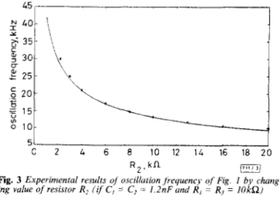
Fig. 3 Experimental results of osciilulion Jrryuency
of
Fin. I by charrg- i g value of resistor R, (if C, = C2 = 1.2nF und R, = R, = IOkRJx experiment ideal curve
Experimental results: To verify the theoretical analysis, we imple- mented the proposed oscillator in Fig. I. The CClI- and C C I i were realised by a commercial operational amplifier (LF3S6) and bipolar transistor array (CA3096) [9, IO]. Fig. 2 shows a typical output waveform of Fig. 1 with C , = C2 = 1.2nF and R , = R, = R, = lOkR and the kSV power supply. Fig. 3 shows the experi-
mental results of the oscillation frequency of Fig. 1 by varying the
%ani et al. [4]
Bhaskaretd [5]
Chang [61
Proposed
Conclusions: A single-resistance-controlled sinusoidal oscillator using a CCI+ and a CCII- is presented. It only uses two grounded capacitors and three grounded resistors. Its oscillation frecluency
can be independently controlled by a grounded resistor. Its passive %sensitivities are all low. This oscillator provides the following advantages: (i) independently controllable oscillation frequency and condition by grounded resistors, (ii) easy conversion into a voltage-controlled oscillator, (iii) all the passive components which are suitable for IC implementation are grounded, (iv) very good frequency stability. The experimental results confirm the theoreti- cal analyses.
0 IEE 1995
Electronics Letters Online No: 19950259
Shen-luan Liu (Department of Electrical Engineering, National Taiwan
University, Taipei, Taiwan 10664, Republic of China)
I9 December I994 Active Grounded Grounded Floating Floating compnents capacitors resistors capacitors resistors
3 1 3 2 2
2 2 1 0 2
3 2 3 0 0
2 2 3 0 0
References
SMITH, K.c., and SEDRA. A.: ‘The current conveyor: A new circuit building block’, IEEE Trans., 1968, CT-15, pp. 1368-1369 SEDRA. A., and SMITH. K.c.: ‘A second generation current conveyor and its applications’, IEEE Trans., 1970, f f - 1 7 , pp. 132-134 NANDI, R., and NANDI, s.: ‘Insensitive minimal-RC sinewave generators with single resistor control’, IEEE Circuits Syst. Mag., December 1982, pp. 11-13
SENANI. R., and SINGH, v.K.: ‘Single-element-controlled sinusoidal oscillator employing single current conveyor IC‘, Electron. Lett., 1992, 28, pp. 414-415
BHASKAR, D.R., and SENANI. R.: ‘New current-conveyor-based single-
resistance-controlledlvoltage-controlled oscillator employing grounded capacitors’, Electron. Lett., 1993, 29, pp, 612-614
CHANG, c.M.: ‘Novel current-conveyor-based single-resistance-
controlledlvoltage-controlled oscillator employing grounded resistors and capacitors’, Electron. Lett., 1994, 30, pp. 181-183
n H u s A N , M., and NEWCOMB, R.w.: ‘Grounding of capacitors in integrated circuits’, Electron. L.ett., 1967, 3, pp. 148-149
SENANI. R.: ‘On the transformation of RC active oscillators’, IEEE
Trans., 1987, CAS-24, pp. 109-1093
WILSON. 8 . : ‘High-performance current conveyor implementation’,
Electron. Lett., 1984, 20, pp. 990-991
10 FAnRE, A : ‘Wideband translinear current conveyor’, Electron. Lett., 1984, 20, pp. 241-242
Third- eneration current conveyor: a new
hslpruf
active element
A. Fabre
Indexing terms: Current conveyors, Analogue circuifs
A new conveyor, which has been called the thud generation current conveyor (CCIII), is introducad. It is defined from the general equations that describe the first and second generation current conveyors. As an example of its possibilities, the use of the Circuit as a floating current sensing device is investigated. Its class AB implementation, obtained from two second gaeration current conveyors, is given. Some simulation results arc also
reported, the circuits being implemented fram complementary bipolar arrays.
Introduction: The first and second generation current conveyors (respectively designated as CCI and CCII) were introduced in 1968
and 1970 [l
-
31. They are now widelyused
principally in the ana- logue domain, to implement a significant number of high-perform- ance signal-processing functions. The general symbol associated with them is shown in Fig. 1.X,
Y and 2 are their input-output ports and ground is the reference. These conveyors can both be described using the following matrix-relation:/ i v ) z ( ! O
;
b”) (;)
0(1)
b characterises their current transfer from
X
to2.
For b positive, the circuit is a positive transfer conveyor. This becomes a wn- veyor with negative transfer when b is negative. a is related to thenature of the conveyor. Thus, only two general classes of current conveyors, with either a = I or a
=
0, havebeen described up to
now. For a = 1, the circuit is a first generation current conveyor (CCI). It is called a second generation conveyor (CCII) for a = 0, [I-
51. A new conveyor, which corresponds to a = -1, is intro- duced in this Letter. Owing to its analogy with the preceding con- veyors, we propose to designate this as the third generation current conveyor (CCIII). This new conveyor will be very useful to take out the current flowing through a floating branch of a circuit.cc
VJt)
I
=I-
-
mFig. 1 General current conveyor symbol
It may also be advantageously used as the input cell of probes and current measuring devices. Its usefulness in current-mode circuits will be illustrated first. Then, its implementation from two CCIIs will be given. Some simulation results obtained from bipolar tran- sistors of complementary arrays will also be indicated.
active network JV
components
’CO
b c m
Fa.
2 General configurntion for a current processing circuit, and outputcurrents
a General configuration for a current p r e s s i n g circuit b Output current flowing to ground
c Floating output current